EP1209367A1 - Dynamically stable flow amplifying poppet valve - Google Patents
Dynamically stable flow amplifying poppet valve Download PDFInfo
- Publication number
- EP1209367A1 EP1209367A1 EP01123947A EP01123947A EP1209367A1 EP 1209367 A1 EP1209367 A1 EP 1209367A1 EP 01123947 A EP01123947 A EP 01123947A EP 01123947 A EP01123947 A EP 01123947A EP 1209367 A1 EP1209367 A1 EP 1209367A1
- Authority
- EP
- European Patent Office
- Prior art keywords
- valve
- poppet valve
- poppet
- fluid
- valve assembly
- Prior art date
- Legal status (The legal status is an assumption and is not a legal conclusion. Google has not performed a legal analysis and makes no representation as to the accuracy of the status listed.)
- Granted
Links
- 239000012530 fluid Substances 0.000 claims abstract description 92
- 230000001105 regulatory effect Effects 0.000 claims description 5
- 230000010355 oscillation Effects 0.000 abstract description 8
- 230000000694 effects Effects 0.000 abstract description 3
- 230000002349 favourable effect Effects 0.000 description 2
- 239000000463 material Substances 0.000 description 2
- 229910000851 Alloy steel Inorganic materials 0.000 description 1
- 230000004323 axial length Effects 0.000 description 1
- 238000010276 construction Methods 0.000 description 1
- 230000001276 controlling effect Effects 0.000 description 1
- 230000007812 deficiency Effects 0.000 description 1
- 230000002093 peripheral effect Effects 0.000 description 1
- 238000007789 sealing Methods 0.000 description 1
- 238000013022 venting Methods 0.000 description 1
Images

Classifications
-
- F—MECHANICAL ENGINEERING; LIGHTING; HEATING; WEAPONS; BLASTING
- F15—FLUID-PRESSURE ACTUATORS; HYDRAULICS OR PNEUMATICS IN GENERAL
- F15B—SYSTEMS ACTING BY MEANS OF FLUIDS IN GENERAL; FLUID-PRESSURE ACTUATORS, e.g. SERVOMOTORS; DETAILS OF FLUID-PRESSURE SYSTEMS, NOT OTHERWISE PROVIDED FOR
- F15B13/00—Details of servomotor systems ; Valves for servomotor systems
- F15B13/02—Fluid distribution or supply devices characterised by their adaptation to the control of servomotors
- F15B13/04—Fluid distribution or supply devices characterised by their adaptation to the control of servomotors for use with a single servomotor
- F15B13/0401—Valve members; Fluid interconnections therefor
- F15B13/0407—Means for damping the valve member movement
-
- F—MECHANICAL ENGINEERING; LIGHTING; HEATING; WEAPONS; BLASTING
- F15—FLUID-PRESSURE ACTUATORS; HYDRAULICS OR PNEUMATICS IN GENERAL
- F15B—SYSTEMS ACTING BY MEANS OF FLUIDS IN GENERAL; FLUID-PRESSURE ACTUATORS, e.g. SERVOMOTORS; DETAILS OF FLUID-PRESSURE SYSTEMS, NOT OTHERWISE PROVIDED FOR
- F15B13/00—Details of servomotor systems ; Valves for servomotor systems
- F15B13/02—Fluid distribution or supply devices characterised by their adaptation to the control of servomotors
- F15B13/04—Fluid distribution or supply devices characterised by their adaptation to the control of servomotors for use with a single servomotor
- F15B13/0401—Valve members; Fluid interconnections therefor
- F15B13/0405—Valve members; Fluid interconnections therefor for seat valves, i.e. poppet valves
-
- Y—GENERAL TAGGING OF NEW TECHNOLOGICAL DEVELOPMENTS; GENERAL TAGGING OF CROSS-SECTIONAL TECHNOLOGIES SPANNING OVER SEVERAL SECTIONS OF THE IPC; TECHNICAL SUBJECTS COVERED BY FORMER USPC CROSS-REFERENCE ART COLLECTIONS [XRACs] AND DIGESTS
- Y10—TECHNICAL SUBJECTS COVERED BY FORMER USPC
- Y10T—TECHNICAL SUBJECTS COVERED BY FORMER US CLASSIFICATION
- Y10T137/00—Fluid handling
- Y10T137/8593—Systems
- Y10T137/86493—Multi-way valve unit
- Y10T137/86574—Supply and exhaust
- Y10T137/86582—Pilot-actuated
- Y10T137/8659—Variable orifice-type modulator
Definitions
- This invention relates generally to a poppet valve for metering the flow of fluid and more specifically to a flow amplifying poppet valve.
- a poppet is a common type of low leakage, flow amplifying hydraulic control valve.
- a type of low leakage poppet valve is described in U.S. Patent No. 5,137,254 and includes a cylindrical poppet valve having a poppet seat sealing against a valve seat. Fluid flow is metered between an inlet and outlet port by controllably moving the poppet valve off the valve seat.
- the poppet valve includes slots to establish fluid communication between the inlet and a control chamber disposed behind the poppet valve and opposite the outlet.
- the fluid pressure in the control chamber exerts a closing force on the poppet valve holding it against the valve seat.
- a spring holds the poppet valve against the valve seat when pressure in the inlet, control chamber and outlet are equal. Adjusting fluid flow from the control chamber to the outlet varies pressure in the control chamber.
- a pilot valve having a variable regulating orifice controls fluid flow out of the control chamber.
- variable regulating orifice is normally closed so that fluid pressure in the control chamber equals the inlet pressure thereby urging the poppet valve against the valve seat. Opening of the pilot valve reduces pressure in the control chamber to urge the poppet valve off the valve seat when the pressure in the control chamber drops below a balance pressure. Controlling the flow through the variable regulating orifice of the pilot valve subsequently controls the degree of opening of the valve element.
- a guide extension extending from the poppet seat guides along the inner diameter of the outlet.
- the guide extension maintains axial alignment of the poppet seat to the valve seat.
- the guide extension is necessary because incoming fluid flow through the inlet creates a moment force tending to tilt the poppet valve. Tilting of the poppet valve within the bore causes friction between the poppet valve and the bore inner diameter. Friction between the poppet valve and the bore inner diameter causes a great deal of unpredictability in the control of the valve.
- the guide extension on the poppet seat eliminates much of the undesirable unpredictability by preventing tilting of the valve in the bore. However, as the valve opens the guide extension is pulled out of the inlet leaving progressively less of the guide extension to prevent tilting of the poppet valve. Further, in a fully open position, the guide extension is completely clear of the outlet, and provides no resistance to tilting.
- the present invention is directed to overcome one or more of the problems as set forth above.
- a flow amplifying poppet valve assembly for metering fluid flow.
- the valve assembly comprises a housing defining a bore and including an inlet and an outlet presenting a valve seat.
- a poppet valve is slidably disposed within the bore and includes a poppet seat for engaging the valve seat to meter the flow of fluid between the inlet and the outlet.
- the poppet valve and housing have radially overlapping shoulders movable axially toward and away from each other to define a pressure chamber that accumulates fluid for dampening poppet valve oscillation.
- the subject invention overcomes the deficiencies of prior art flow amplifying poppet valves by including a pressure chamber defined by overlapping shoulders on the poppet valve and the housing.
- the pressure chamber reduces the effects of pressure and fluid flow fluctuations on poppet valve position. Further, the overlapping shoulders create a constant guide length over the entire range of movement of the poppet valve thereby preventing poppet valve tilting.
- the valve assembly 10 includes a housing 12 defining a bore 14 and including an inlet 16 and an outlet 18.
- the outlet 18 has a first inner diameter 20 that defines a valve seat 22.
- a second inner diameter 24 of the bore 14 intersects the inlet 16.
- a third inner diameter 26 of the bore 14 cooperates with the second inner diameter 24 to define a housing shoulder 28.
- the housing shoulder 28 projects radially into the bore 14.
- a fourth inner diameter 30 arranged opposite the outlet 18 defines a control chamber 32.
- a poppet valve 34 is slidably disposed within the bore 14 and includes a poppet seat 36 engaging the valve seat 22.
- the poppet valve 34 meters the flow of fluid between the inlet 16 and the outlet 18.
- a guide extension 38 extends from the poppet seat 36 into the first inner diameter 20 of the outlet 18.
- the guide extension 38 includes a plurality of V-shaped cross-slots 40. These V-shaped cross-slots 40 might be replaced with a plurality of drilled holes and/or U-shaped cross-slots.
- the poppet valve 34 is preferably constructed of a steel alloy. As appreciated, the material selected for construction of the poppet valve requires favorable wear properties to provide favorable durability characteristics. It should be understood that it is within the contemplation of this invention that the poppet valve may comprise any material known by those knowledgeable in the art.
- the poppet valve 34 includes internal passages 41.
- the poppet valve 34 also includes slots 42 disposed about the periphery thereof.
- the internal passages 41 establish fluid communication between the inlet 16 and slots 42.
- the slots 42 establish fluid communication between the inlet 16 and the control chamber 32 through the internal passages 41.
- a spring 44 is disposed in the control chamber 32 to urge the poppet valve 34 against the valve seat 22.
- a flow regulating passage 46 communicates the control chamber 32 with the outlet 18.
- a pilot valve 48 having a variable orifice controls fluid flow from the control chamber 32 to the outlet 18.
- the poppet valve 34 and housing 12 have radially overlapping shoulders 50,28 movable axially toward and away from each other that define a pressure chamber 52 to accumulate fluid for dampening poppet valve oscillation.
- the poppet valve has a diameter 72 that guides along the housing shoulder 28.
- the housing shoulder 28 extends into the bore 14 and contacts the poppet valve 34.
- the housing 12 has a guide length 53.
- the shoulder 28 has an axial length 54.
- the guide length 53 maintains guiding contact with the poppet valve 34 through the entire range of possible poppet valve 34 movement.
- the housing 12 includes a first fluid passage 56 to establish fluid communication between the inlet 16 and the pressure chamber 52.
- a damper orifice 58 positioned within the first fluid passage 56 restricts fluid flow between the pressure chamber 52 and the inlet 16. Restricting fluid flow into and out of the pressure chamber 52 smoothes poppet valve 34 movement by dampening oscillation caused by pressure and fluid flow fluctuations.
- the first fluid passage 56 is not machined as a direct passage between the pressure chamber 52 and the inlet 16.
- the housing 12 is configured to establish communication between the inlet 16 and pressure chamber 52 through a second valve assembly 60 including the damper orifice 58, a check valve 62 and a pressure relief valve 64 arranged in parallel.
- the second valve assembly 60 may be disposed within the housing 12 or in a secondary housing.
- the check valve 62 allows fluid to freely enter the pressure chamber 52, thereby bypassing the damper orifice 58.
- the pressure relief valve 64 provides for the venting of abnormally high pressure out of the pressure chamber 52.
- the pressure relief valve 64 may be of any type known in the art.
- the second valve assembly includes a poppet type check valve 66.
- the poppet type check valve is disposed within a valve assembly body 67.
- the valve assembly body 67 seals against a valve assembly body seat 69.
- a spring 71 urges the valve assembly body against the body seat 69.
- the damper orifice 58 in the third embodiment is disposed within the valve assembly body 67 to provide the flow of a fluid into and out of the pressure chamber 52 under normal operation.
- a pressure relief valve 68 built into the poppet type check valve 66 vents abnormally high-pressure fluid out of the pressure chamber 52.
- the valve assembly body 67 allows fluid flow from the inlet 16 to pass through the poppet type check valve 66 and the orifice 58 to enter the pressure chamber 52.
- the second valve assembly 60 communicates as a second fluid passage 70 between the inlet 16 and the pressure chamber 52.
- the first fluid passage 56 remains machined in the housing 12 as a direct path between the pressure chamber 52 and the inlet 16.
- the valve assembly 60 is disposed within the second fluid passage 70.
- the second fluid passage 70 and the second valve assembly 60 may be disposed separate from the housing 12.
- the second fluid passage 70 and second valve assembly 60 include the same check valve 62 and the pressure relief valve 64 arranged within the second fluid passage 56 as shown in Figure 2.
- the damper orifice 58 is disposed in the first fluid passage 56.
- the second valve assembly 60 communicates as a second fluid passage 70 between the inlet 16 and the pressure chamber 52.
- the first fluid passage 56 remains machined in the housing 12 as a direct path between the pressure chamber 52 and the inlet 16.
- the second fluid passage 70 and second valve assembly 60 include the poppet type check valve 66 with the built in pressure relief valve 68.
- the damper orifice 58 is disposed in the first fluid passage 56 as in the first embodiment shown in Figure 1.
- the pilot valve 48 is opened to allow flow out of the control chamber 32.
- the accompanying pressure drop between the inlet 16 and the control chamber 32 causes a pressure imbalance that moves the poppet valve 34 from the valve seat 22.
- the amount that the poppet valve 34 lifts from the valve seat 22 is nearly proportional to the amount of fluid flow out of the control chamber 32 and the magnitude of the pressure drop between the inlet 16 and the control chamber 32.
- a guide extension 38 extends from the poppet seat 36 into the outlet 18 to axially align the poppet seat 36 with the valve seat 22.
- the V-shaped or U-shaped cross-slots 40 of the guide extension 38 provide a fluid flow path from the inlet 16 to the outlet 18.
- fluid flow begins to flow through the slots 40.
- the poppet valve is progressively lifted from the valve seat 22 an increasing amount of the slots 40 are uncovered allowing proportionally more fluid flow.
- Tilting of the poppet valve 34 is prevented in the subject invention by the guide length 53 of the bore contacting the poppet valve 34.
- the guide length 53 guides the poppet valve 34 through the entire range of poppet valve 34 movement.
- the guide length 53 maintains a constant sliding contact between with the poppet valve 34, thereby maintaining a constant L/D ratio.
- the pressure chamber 52 is defined by radially overlapping shoulders 28,50 of the housing 12 and the poppet valve 34 and fills with fluid to act as a damper to prevent oscillation of the poppet valve 34.
- the fluid passage 56 establishes communication between the pressure chamber 52 and the inlet 16.
- the damper orifice 58 in the first fluid passage 56 restricts the flow of fluid into and out of the pressure chamber 52 to dampening oscillations of the poppet valve 34.
- the poppet valve 34 when the poppet valve 34 opens suddenly the pressure chamber size increases and more fluid is drawn into the pressure chamber 52 from the inlet 16. However, the damper orifice 58 will restrict the flow of fluid into the pressure chamber 52, creating a vacuum in the pressure chamber 52 that causes the poppet valve 34 to hesitate.
- the subject invention provides a check valve 62 to correct this problem.
- the check valve 62 is arranged to allow fluid to enter the pressure chamber 52, but not exit. Therefore, when the poppet valve 34 opens suddenly the check valve 62 provides a second unrestricted passage for fluid to flow into the pressure chamber 52.
- the unrestricted passage through the check valve 62 allows fluid to freely enter the pressure chamber 52 as quickly as the volume of the pressure chamber increases thereby, eliminating the vacuum in the pressure chamber 52, and preventing poppet hesitation.
- suddenly closing the poppet valve 34 may create a sudden abnormally high pressure in the pressure chamber 52, caused by the restriction of fluid through the damper orifice 58.
- High fluid pressure in the pressure chamber 52 causes the poppet valve 34 to hesitate when moving toward a closed position.
- the subject invention eliminates abnormally high pressure in the pressure chamber 52 with the pressure relief valve 64 arranged in parallel with the check valve 62.
- High pressure in the pressure chamber 52 caused by the sudden closing of the poppet valve 34 vents from the pressure chamber 52 through the pressure relief valve 64 and into the inlet 16.
- Abnormally high fluid pressure is routed around the restrictive damper orifice 58 to prevent poppet valve 34 hesitation.
- the second valve assembly 60 comprises the poppet type check valve 66.
- the damper orifice 58 is integrated into the valve assembly body 67 for the poppet type check valve 66.
- the poppet type check valve 66 allows fluid to flow freely between the pressure chamber 52 and the inlet 16.
- a relief valve 68 built. into the poppet check valve 66 vents abnormally high pressure from the pressure chamber 52. Vacuum created by suddenly opening the poppet valve is eliminated by the valve assembly body 67.
- the valve assembly body 67 will lift off the body seat 69 to allow unrestricted flow of fluid into the pressure chamber 52, thereby preventing hesitation of the poppet valve 34.
- a second fluid passage 70 including the second valve assembly 60, between the inlet 16 and the pressure chamber 52 is provided.
- the check valve 62 and the pressure relief valve 64 are arranged in parallel.
- the damper orifice 58 is disposed in the first fluid passage 56 separate from the second valve assembly 60.
- the fifth embodiment of the subject invention substitutes a poppet type check valve 66 disposed within a valve assembly body 67 as the second valve assembly 60.
- a pressure relief valve 68 is built into the poppet type check valve.
- the damper orifice 58 is disposed in the first fluid passage 56 separate from the poppet type check valve 66 and valve assembly body 67.
Landscapes
- Engineering & Computer Science (AREA)
- Physics & Mathematics (AREA)
- Fluid Mechanics (AREA)
- Mechanical Engineering (AREA)
- General Engineering & Computer Science (AREA)
- Safety Valves (AREA)
- Details Of Valves (AREA)
Abstract
Description
- This invention relates generally to a poppet valve for metering the flow of fluid and more specifically to a flow amplifying poppet valve.
- A poppet is a common type of low leakage, flow amplifying hydraulic control valve. A type of low leakage poppet valve is described in U.S. Patent No. 5,137,254 and includes a cylindrical poppet valve having a poppet seat sealing against a valve seat. Fluid flow is metered between an inlet and outlet port by controllably moving the poppet valve off the valve seat.
- The poppet valve includes slots to establish fluid communication between the inlet and a control chamber disposed behind the poppet valve and opposite the outlet. The fluid pressure in the control chamber exerts a closing force on the poppet valve holding it against the valve seat. A spring holds the poppet valve against the valve seat when pressure in the inlet, control chamber and outlet are equal. Adjusting fluid flow from the control chamber to the outlet varies pressure in the control chamber. A pilot valve having a variable regulating orifice controls fluid flow out of the control chamber.
- The variable regulating orifice is normally closed so that fluid pressure in the control chamber equals the inlet pressure thereby urging the poppet valve against the valve seat. Opening of the pilot valve reduces pressure in the control chamber to urge the poppet valve off the valve seat when the pressure in the control chamber drops below a balance pressure. Controlling the flow through the variable regulating orifice of the pilot valve subsequently controls the degree of opening of the valve element.
- A guide extension extending from the poppet seat guides along the inner diameter of the outlet. The guide extension maintains axial alignment of the poppet seat to the valve seat. The guide extension is necessary because incoming fluid flow through the inlet creates a moment force tending to tilt the poppet valve. Tilting of the poppet valve within the bore causes friction between the poppet valve and the bore inner diameter. Friction between the poppet valve and the bore inner diameter causes a great deal of unpredictability in the control of the valve.
- The guide extension on the poppet seat eliminates much of the undesirable unpredictability by preventing tilting of the valve in the bore. However, as the valve opens the guide extension is pulled out of the inlet leaving progressively less of the guide extension to prevent tilting of the poppet valve. Further, in a fully open position, the guide extension is completely clear of the outlet, and provides no resistance to tilting.
- An additional problem encountered in the control of a poppet valve is oscillation. Fluctuations in fluid pressure or fluid flow cause the poppet valve to oscillate. An oscillating poppet valve creates an oscillating fluid flow or fluid pressure at the outlet and is therefore undesirable.
- For these reasons, a poppet valve configuration capable of reducing the effects of pressure fluctuations, and capable of preventing poppet valve tilting is needed.
- The present invention is directed to overcome one or more of the problems as set forth above.
- In one aspect of the invention, a flow amplifying poppet valve assembly for metering fluid flow is disclosed. The valve assembly comprises a housing defining a bore and including an inlet and an outlet presenting a valve seat. A poppet valve is slidably disposed within the bore and includes a poppet seat for engaging the valve seat to meter the flow of fluid between the inlet and the outlet. The poppet valve and housing have radially overlapping shoulders movable axially toward and away from each other to define a pressure chamber that accumulates fluid for dampening poppet valve oscillation.
- The subject invention overcomes the deficiencies of prior art flow amplifying poppet valves by including a pressure chamber defined by overlapping shoulders on the poppet valve and the housing. The pressure chamber reduces the effects of pressure and fluid flow fluctuations on poppet valve position. Further, the overlapping shoulders create a constant guide length over the entire range of movement of the poppet valve thereby preventing poppet valve tilting.
- Other advantages of the present invention will be readily appreciated as the same becomes better understood by reference to the following detailed description when considered in connection with the accompanying drawings wherein:
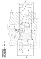
- Figure 1 is a cross-sectional schematic view of a first embodiment of the valve assembly;
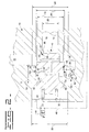
- Figure 2 is a cross-sectional schematic view of a second embodiment of the valve assembly;
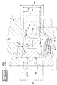
- Figure 3 is a cross-sectional schematic view of a third embodiment of the valve assembly;
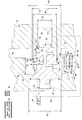
- Figure 4 is a cross-sectional schematic view of a fourth embodiment of the valve assembly; and
- Figure 5 is a cross-sectional schematic view of a fifth embodiment of the valve assembly.
-
- Referring to the Figures, wherein like numerals indicate like or corresponding parts throughout the several views, a dynamically stable flow amplifying poppet valve assembly for metering fluid flow is generally shown at 10. Referring to Figure 1, the
valve assembly 10 includes ahousing 12 defining abore 14 and including aninlet 16 and anoutlet 18. Theoutlet 18 has a firstinner diameter 20 that defines avalve seat 22. A secondinner diameter 24 of thebore 14 intersects theinlet 16. A thirdinner diameter 26 of thebore 14 cooperates with the secondinner diameter 24 to define ahousing shoulder 28. Thehousing shoulder 28 projects radially into thebore 14. A fourthinner diameter 30 arranged opposite theoutlet 18 defines acontrol chamber 32. - A
poppet valve 34 is slidably disposed within thebore 14 and includes apoppet seat 36 engaging thevalve seat 22. Thepoppet valve 34 meters the flow of fluid between theinlet 16 and theoutlet 18. Aguide extension 38 extends from thepoppet seat 36 into the firstinner diameter 20 of theoutlet 18. Theguide extension 38 includes a plurality of V-shaped cross-slots 40. These V-shaped cross-slots 40 might be replaced with a plurality of drilled holes and/or U-shaped cross-slots. - The
poppet valve 34 is preferably constructed of a steel alloy. As appreciated, the material selected for construction of the poppet valve requires favorable wear properties to provide favorable durability characteristics. It should be understood that it is within the contemplation of this invention that the poppet valve may comprise any material known by those knowledgeable in the art. - The
poppet valve 34 includesinternal passages 41. Thepoppet valve 34 also includesslots 42 disposed about the periphery thereof. Theinternal passages 41 establish fluid communication between theinlet 16 andslots 42. Theslots 42 establish fluid communication between theinlet 16 and thecontrol chamber 32 through theinternal passages 41. Aspring 44 is disposed in thecontrol chamber 32 to urge thepoppet valve 34 against thevalve seat 22. Aflow regulating passage 46 communicates thecontrol chamber 32 with theoutlet 18. Apilot valve 48 having a variable orifice controls fluid flow from thecontrol chamber 32 to theoutlet 18. - The
poppet valve 34 andhousing 12 have radially overlappingshoulders pressure chamber 52 to accumulate fluid for dampening poppet valve oscillation. The poppet valve has adiameter 72 that guides along thehousing shoulder 28. Thehousing shoulder 28 extends into thebore 14 and contacts thepoppet valve 34. Thehousing 12 has aguide length 53. Theshoulder 28 has anaxial length 54. Theguide length 53 maintains guiding contact with thepoppet valve 34 through the entire range ofpossible poppet valve 34 movement. - The
housing 12 includes afirst fluid passage 56 to establish fluid communication between theinlet 16 and thepressure chamber 52. Adamper orifice 58 positioned within thefirst fluid passage 56 restricts fluid flow between thepressure chamber 52 and theinlet 16. Restricting fluid flow into and out of thepressure chamber 52smoothes poppet valve 34 movement by dampening oscillation caused by pressure and fluid flow fluctuations. - In a second embodiment of the subject invention shown in Figure 2, the
first fluid passage 56 is not machined as a direct passage between thepressure chamber 52 and theinlet 16. Thehousing 12 is configured to establish communication between theinlet 16 andpressure chamber 52 through asecond valve assembly 60 including thedamper orifice 58, acheck valve 62 and apressure relief valve 64 arranged in parallel. As is appreciated, thesecond valve assembly 60 may be disposed within thehousing 12 or in a secondary housing. Thecheck valve 62 allows fluid to freely enter thepressure chamber 52, thereby bypassing thedamper orifice 58. Thepressure relief valve 64 provides for the venting of abnormally high pressure out of thepressure chamber 52. Thepressure relief valve 64 may be of any type known in the art. - In a third embodiment shown in Figure 3, the second valve assembly includes a poppet
type check valve 66. The poppet type check valve is disposed within avalve assembly body 67. Thevalve assembly body 67 seals against a valveassembly body seat 69. Aspring 71 urges the valve assembly body against thebody seat 69. Thedamper orifice 58 in the third embodiment is disposed within thevalve assembly body 67 to provide the flow of a fluid into and out of thepressure chamber 52 under normal operation. Apressure relief valve 68 built into the poppettype check valve 66 vents abnormally high-pressure fluid out of thepressure chamber 52. Thevalve assembly body 67 allows fluid flow from theinlet 16 to pass through the poppettype check valve 66 and theorifice 58 to enter thepressure chamber 52. - In a fourth embodiment of the subject invention shown in Figure 4, the
second valve assembly 60 communicates as asecond fluid passage 70 between theinlet 16 and thepressure chamber 52. Thefirst fluid passage 56 remains machined in thehousing 12 as a direct path between thepressure chamber 52 and theinlet 16. Thevalve assembly 60 is disposed within thesecond fluid passage 70. As appreciated, thesecond fluid passage 70 and thesecond valve assembly 60 may be disposed separate from thehousing 12. Thesecond fluid passage 70 andsecond valve assembly 60 include thesame check valve 62 and thepressure relief valve 64 arranged within thesecond fluid passage 56 as shown in Figure 2. However, in the fourth embodiment thedamper orifice 58 is disposed in thefirst fluid passage 56. - In a fifth embodiment of the subject invention shown in Figure 5, the
second valve assembly 60 communicates as asecond fluid passage 70 between theinlet 16 and thepressure chamber 52. Thefirst fluid passage 56 remains machined in thehousing 12 as a direct path between thepressure chamber 52 and theinlet 16. Thesecond fluid passage 70 andsecond valve assembly 60 include the poppettype check valve 66 with the built inpressure relief valve 68. In this embodiment, thedamper orifice 58 is disposed in thefirst fluid passage 56 as in the first embodiment shown in Figure 1. - With respect to the embodiment shown in Figure 1, when the
pilot valve 48 is closed fluid from theinlet 16 proceeds though theinternal passages 41 andperipheral slots 42 of thepoppet valve 34 to fill thecontrol chamber 32. Because thepilot valve 48 is closed, the fluid pressure within thecontrol chamber 32 is equal to the fluid pressure at theinlet 16. Fluid pressure from theinlet 16 acts within thecontrol chamber 32 on thepoppet valve 34 to hold thepoppet seat 36 against thevalve seat 22. When a differential fluid pressure between theinlet 16 and theoutlet 18 is less than the force of thespring 44, thespring 44 will urge thepoppet valve 34 closed against thevalve seat 22. - To move the
poppet valve 34 off thevalve seat 22 thepilot valve 48 is opened to allow flow out of thecontrol chamber 32. The accompanying pressure drop between theinlet 16 and thecontrol chamber 32 causes a pressure imbalance that moves thepoppet valve 34 from thevalve seat 22. The amount that thepoppet valve 34 lifts from thevalve seat 22 is nearly proportional to the amount of fluid flow out of thecontrol chamber 32 and the magnitude of the pressure drop between theinlet 16 and thecontrol chamber 32. - A
guide extension 38 extends from thepoppet seat 36 into theoutlet 18 to axially align thepoppet seat 36 with thevalve seat 22. The V-shaped orU-shaped cross-slots 40 of theguide extension 38 provide a fluid flow path from theinlet 16 to theoutlet 18. As thepoppet valve 34 lifts off thevalve seat 22 fluid flow begins to flow through theslots 40. As the poppet valve is progressively lifted from thevalve seat 22 an increasing amount of theslots 40 are uncovered allowing proportionally more fluid flow. - Moving the
poppet seat 36 off thevalve seat 22 progressively shortens the amount of theguide extension 38 extending into theoutlet 18.Smooth poppet valve 34 travel is obtained by maintaining a constant ratio (L/D) between theguide length 53 and thepoppet diameter 26. A constant L/D ratio reduces excessive friction caused by tilting of thepoppet valve 34. If theguide extension 38 were the only guide for thepoppet valve 34, once clear of theoutlet 18, the effective L/D ratio would be negligible. Thepoppet valve 34 would tilt because of flow forces from the flow of the fluid between theinlet 16 andoutlet 18. Thepoppet valve 34 tilt causes contact with the inner diameter of thebore 14, thereby creating friction that degrades the smooth movement and repeatability of thepoppet valve 34. - Tilting of the
poppet valve 34 is prevented in the subject invention by theguide length 53 of the bore contacting thepoppet valve 34. Theguide length 53 guides thepoppet valve 34 through the entire range ofpoppet valve 34 movement. Theguide length 53 maintains a constant sliding contact between with thepoppet valve 34, thereby maintaining a constant L/D ratio. - The
pressure chamber 52 is defined by radially overlappingshoulders housing 12 and thepoppet valve 34 and fills with fluid to act as a damper to prevent oscillation of thepoppet valve 34. Thefluid passage 56 establishes communication between thepressure chamber 52 and theinlet 16. Thedamper orifice 58 in thefirst fluid passage 56 restricts the flow of fluid into and out of thepressure chamber 52 to dampening oscillations of thepoppet valve 34. - Referring to the embodiment of Figure 2, when the
poppet valve 34 opens suddenly the pressure chamber size increases and more fluid is drawn into thepressure chamber 52 from theinlet 16. However, thedamper orifice 58 will restrict the flow of fluid into thepressure chamber 52, creating a vacuum in thepressure chamber 52 that causes thepoppet valve 34 to hesitate. The subject invention provides acheck valve 62 to correct this problem. Thecheck valve 62 is arranged to allow fluid to enter thepressure chamber 52, but not exit. Therefore, when thepoppet valve 34 opens suddenly thecheck valve 62 provides a second unrestricted passage for fluid to flow into thepressure chamber 52. The unrestricted passage through thecheck valve 62 allows fluid to freely enter thepressure chamber 52 as quickly as the volume of the pressure chamber increases thereby, eliminating the vacuum in thepressure chamber 52, and preventing poppet hesitation. - Suddenly closing the
poppet valve 34 may create a sudden abnormally high pressure in thepressure chamber 52, caused by the restriction of fluid through thedamper orifice 58. High fluid pressure in thepressure chamber 52 causes thepoppet valve 34 to hesitate when moving toward a closed position. The subject invention eliminates abnormally high pressure in thepressure chamber 52 with thepressure relief valve 64 arranged in parallel with thecheck valve 62. High pressure in thepressure chamber 52 caused by the sudden closing of thepoppet valve 34 vents from thepressure chamber 52 through thepressure relief valve 64 and into theinlet 16. Abnormally high fluid pressure is routed around therestrictive damper orifice 58 to preventpoppet valve 34 hesitation. - Referring to the embodiment shown in Figure 3, the
second valve assembly 60 comprises the poppettype check valve 66. Thedamper orifice 58 is integrated into thevalve assembly body 67 for the poppettype check valve 66. The poppettype check valve 66 allows fluid to flow freely between thepressure chamber 52 and theinlet 16. Arelief valve 68 built. into thepoppet check valve 66 vents abnormally high pressure from thepressure chamber 52. Vacuum created by suddenly opening the poppet valve is eliminated by thevalve assembly body 67. Thevalve assembly body 67 will lift off thebody seat 69 to allow unrestricted flow of fluid into thepressure chamber 52, thereby preventing hesitation of thepoppet valve 34. - Referring to the embodiments shown in Figures 4 and 5, a
second fluid passage 70 including thesecond valve assembly 60, between theinlet 16 and thepressure chamber 52 is provided. Referring specifically to Figure 4, thecheck valve 62 and thepressure relief valve 64 are arranged in parallel. In this embodiment, thedamper orifice 58 is disposed in thefirst fluid passage 56 separate from thesecond valve assembly 60. - Referring to Figure 5, the fifth embodiment of the subject invention substitutes a poppet
type check valve 66 disposed within avalve assembly body 67 as thesecond valve assembly 60. Apressure relief valve 68 is built into the poppet type check valve. Thedamper orifice 58 is disposed in thefirst fluid passage 56 separate from the poppettype check valve 66 andvalve assembly body 67. - Other aspects, objects and advantages of this invention can be obtained from a study of the drawings, the disclosure and the appended claims.
Claims (19)
- A valve assembly comprising:wherein said poppet valve and said housing are configured to provide a sliding relationship therebetween over an entire range of movement of said poppet valve.a housing defining an inlet and an outlet;a poppet valve slideably disposed within the housing and being operable to control a flow of fluid between said inlet and said outlet;a pressure chamber defined between said housing and said poppet valve and being structured and arranged to receive fluid therein, wherein movement of said poppet valve being dampened by said fluid in said pressure chamber; andsaid poppet valve including at least one guiding portion in slideable engagement with at least one guiding portion of said poppet valve,
- A valve assembly as in Claim 1, wherein said at least on guiding portion of said housing is a shoulder and said at least one guiding portion of said poppet valve is a shoulder.
- A valve assembly as in Claim 2, further comprising a second guiding portion of said poppet valve comprising a guide extension and a second guiding portion of said housing defined by said outlet of said housing.
- A valve assembly as in claim 1 wherein said housing includes a first fluid passage to establish fluid communication between said inlet and said pressure chamber.
- A valve assembly as in claim 4 wherein said first fluid passage includes a damper orifice that operates to restrict the flow of fluid between said pressure chamber and said inlet.
- A valve assembly as in claim 5 wherein said first fluid passage includes a check valve disposed between said inlet and said pressure chamber that operates to allow the flow of fluid to freely enter said pressure chamber.
- A valve assembly as in claim 6 wherein said first fluid passage includes a pressure relief valve to vent abnormally high fluid pressure from said pressure chamber.
- A valve assembly as in claim 6 wherein said check valve is a poppet valve.
- A valve assembly as in claim 5 including a second fluid passage establishing fluid communication between said inlet and said pressure chamber including a check valve disposed between said inlet and said pressure chamber that operates to allow the flow of fluid to freely enter said pressure chamber.
- A valve assembly as in claim 9 wherein said check valve is a poppet valve.
- A valve assembly as in claim 9 wherein said housing includes a second fluid passage having a pressure relief valve to relieve abnormally high pressure within said pressure chamber.
- A valve assembly as in claim 2 wherein said shoulder of said housing has an inner diameter cooperating with said shoulder of said poppet valve to maintain axial alignment between said poppet valve and said housing.
- A valve assembly as in claim 12 wherein said housing has a guide length and a guide inner diameter, and a ratio between said guide inner diameter and said guide length is constant for any poppet valve position.
- A valve assembly as in claim 1 wherein said housing defines a control chamber disposed at an end of said poppet valve.
- A valve assembly as in claim 14 wherein said poppet valve includes slots about a periphery of said poppet valve and internal passages that operate to establish fluid communication between said inlet and said control chamber.
- A valve assembly as in claim 15 wherein a spring is disposed in said control chamber to urge said poppet valve against a valve seat disposed within said housing and positioned between said inlet and said outlet.
- A valve assembly as in claim 16 including a flow regulating fluid passage establishing fluid communication between said control chamber and said outlet and a variable orifice pilot valve.
- A valve assembly as in claim 3 wherein said guide extension extends from a seat defined by said poppet valve and into said outlet.
- A valve assembly as in claim 18 wherein said guide extension includes slots operative to direct fluid flow between said inlet and said outlet through said slots.
Applications Claiming Priority (2)
| Application Number | Priority Date | Filing Date | Title |
|---|---|---|---|
| US717574 | 1996-09-23 | ||
| US09/717,574 US6557822B1 (en) | 2000-11-21 | 2000-11-21 | Dynamically stable flow amplifying poppet valve |
Publications (2)
| Publication Number | Publication Date |
|---|---|
| EP1209367A1 true EP1209367A1 (en) | 2002-05-29 |
| EP1209367B1 EP1209367B1 (en) | 2006-01-04 |
Family
ID=24882575
Family Applications (1)
| Application Number | Title | Priority Date | Filing Date |
|---|---|---|---|
| EP01123947A Expired - Lifetime EP1209367B1 (en) | 2000-11-21 | 2001-10-08 | Dynamically stable flow amplifying poppet valve |
Country Status (3)
| Country | Link |
|---|---|
| US (1) | US6557822B1 (en) |
| EP (1) | EP1209367B1 (en) |
| DE (1) | DE60116426T2 (en) |
Cited By (2)
| Publication number | Priority date | Publication date | Assignee | Title |
|---|---|---|---|---|
| US6742540B2 (en) | 2002-06-28 | 2004-06-01 | Hyundai Motor Company | Two-way orifice check valve device for hydraulic circuit |
| EP1566551A1 (en) * | 2004-02-20 | 2005-08-24 | Eaton Corporation | Dampened vehicle emergency brake valve |
Families Citing this family (7)
| Publication number | Priority date | Publication date | Assignee | Title |
|---|---|---|---|---|
| US7293579B2 (en) * | 2004-07-08 | 2007-11-13 | Caterpillar Inc. | Poppet valve arrangements |
| US20070045584A1 (en) * | 2005-08-31 | 2007-03-01 | Diamond Power International, Inc. | Low loss poppet valve for a cleaning device and a method of delivering a cleaning fluid therewith |
| EP1930638B1 (en) * | 2006-12-05 | 2011-01-05 | FESTO AG & Co. KG | Softstart valve device |
| US8015989B2 (en) * | 2008-06-09 | 2011-09-13 | Applied Materials, Inc. | Method and apparatus for dampening pressure fluctuations in a fluid delivery system |
| US8684037B2 (en) * | 2009-08-05 | 2014-04-01 | Eaton Corportion | Proportional poppet valve with integral check valve |
| US8291934B2 (en) * | 2010-01-20 | 2012-10-23 | Eaton Corporation | Proportional valve assembly |
| US8770543B2 (en) | 2011-07-14 | 2014-07-08 | Eaton Corporation | Proportional poppet valve with integral check valves |
Citations (5)
| Publication number | Priority date | Publication date | Assignee | Title |
|---|---|---|---|---|
| US4706932A (en) * | 1982-07-16 | 1987-11-17 | Hitachi Construction Machinery Co., Ltd. | Fluid control valve apparatus |
| US5137254A (en) * | 1991-09-03 | 1992-08-11 | Caterpillar Inc. | Pressure compensated flow amplifying poppet valve |
| JPH09256418A (en) * | 1996-03-21 | 1997-09-30 | Hitachi Constr Mach Co Ltd | Pressure control circuit and brake device |
| US5873561A (en) * | 1993-07-16 | 1999-02-23 | Hydrolux S.A.R.L. | Two-port cartridge seat valve |
| US6038957A (en) * | 1995-12-15 | 2000-03-21 | Commercial Intertech Limited | Control valves |
Family Cites Families (5)
| Publication number | Priority date | Publication date | Assignee | Title |
|---|---|---|---|---|
| US5253672A (en) | 1986-01-30 | 1993-10-19 | Kabushiki Kaisha Komatsu Seisakusho | Hydraulic pressure control system |
| US5836335A (en) * | 1991-08-19 | 1998-11-17 | Fluid Power Industries, Inc. | Proportional pressure control valve |
| US5170692A (en) | 1991-11-04 | 1992-12-15 | Vickers, Incorporated | Hydraulic control system |
| DE4223389C2 (en) | 1992-07-16 | 2001-01-04 | Mannesmann Rexroth Ag | Control arrangement for at least one hydraulic consumer |
| US5417402A (en) | 1994-02-10 | 1995-05-23 | Alliedsignal Inc. | Shutoff and pressure regulating valve |
-
2000
- 2000-11-21 US US09/717,574 patent/US6557822B1/en not_active Expired - Fee Related
-
2001
- 2001-10-08 DE DE60116426T patent/DE60116426T2/en not_active Expired - Lifetime
- 2001-10-08 EP EP01123947A patent/EP1209367B1/en not_active Expired - Lifetime
Patent Citations (5)
| Publication number | Priority date | Publication date | Assignee | Title |
|---|---|---|---|---|
| US4706932A (en) * | 1982-07-16 | 1987-11-17 | Hitachi Construction Machinery Co., Ltd. | Fluid control valve apparatus |
| US5137254A (en) * | 1991-09-03 | 1992-08-11 | Caterpillar Inc. | Pressure compensated flow amplifying poppet valve |
| US5873561A (en) * | 1993-07-16 | 1999-02-23 | Hydrolux S.A.R.L. | Two-port cartridge seat valve |
| US6038957A (en) * | 1995-12-15 | 2000-03-21 | Commercial Intertech Limited | Control valves |
| JPH09256418A (en) * | 1996-03-21 | 1997-09-30 | Hitachi Constr Mach Co Ltd | Pressure control circuit and brake device |
Non-Patent Citations (1)
| Title |
|---|
| PATENT ABSTRACTS OF JAPAN vol. 1998, no. 01 30 January 1998 (1998-01-30) * |
Cited By (2)
| Publication number | Priority date | Publication date | Assignee | Title |
|---|---|---|---|---|
| US6742540B2 (en) | 2002-06-28 | 2004-06-01 | Hyundai Motor Company | Two-way orifice check valve device for hydraulic circuit |
| EP1566551A1 (en) * | 2004-02-20 | 2005-08-24 | Eaton Corporation | Dampened vehicle emergency brake valve |
Also Published As
| Publication number | Publication date |
|---|---|
| EP1209367B1 (en) | 2006-01-04 |
| DE60116426T2 (en) | 2006-09-07 |
| DE60116426D1 (en) | 2006-03-30 |
| US6557822B1 (en) | 2003-05-06 |
Similar Documents
| Publication | Publication Date | Title |
|---|---|---|
| US5878647A (en) | Pilot solenoid control valve and hydraulic control system using same | |
| JP2000220603A (en) | Hydraulic control device | |
| US20040206397A1 (en) | Flow regulator with pressure relief combination valve | |
| CN101131167B (en) | Hydraulic control apparatus | |
| WO2007149192A2 (en) | Poppet valve | |
| US6557822B1 (en) | Dynamically stable flow amplifying poppet valve | |
| US8424836B2 (en) | Bidirectional force feedback poppet valve | |
| US5535663A (en) | Operating valve assembly with pressure compensation valve | |
| CN110374949B (en) | Valve and hydraulic system with same | |
| EP0987444A2 (en) | Proportional priority flow regulator with reverse flow control | |
| US6186750B1 (en) | Oil pump control valve spool with pilot pressure relief valve | |
| JP2003519348A (en) | Pressure regulating valve | |
| JPH11257517A (en) | Two-way operating flow opening / closing valve and hydraulic supply device using it | |
| JP2007162848A (en) | Actuator control device | |
| KR100334340B1 (en) | Hydraulic control system | |
| JPH08128405A (en) | Unload valve | |
| KR20200055097A (en) | Relief valve | |
| JP3684459B2 (en) | Flow control valve | |
| JPH0962365A (en) | Pressure compensating flow control valve with check valve | |
| JP2001271803A (en) | Switching valve | |
| JP3872464B2 (en) | Pressure reducing valve device | |
| JP4841369B2 (en) | Actuator control device | |
| JPH063245Y2 (en) | Poppet valve | |
| JPH11344003A (en) | Hydraulic control device | |
| JPH11315809A (en) | Hydraulic control device |
Legal Events
| Date | Code | Title | Description |
|---|---|---|---|
| PUAI | Public reference made under article 153(3) epc to a published international application that has entered the european phase |
Free format text: ORIGINAL CODE: 0009012 |
|
| AK | Designated contracting states |
Kind code of ref document: A1 Designated state(s): AT BE CH CY DE DK ES FI FR GB GR IE IT LI LU MC NL PT SE TR |
|
| AX | Request for extension of the european patent |
Free format text: AL;LT;LV;MK;RO;SI |
|
| 17P | Request for examination filed |
Effective date: 20021002 |
|
| AKX | Designation fees paid |
Designated state(s): DE GB |
|
| 17Q | First examination report despatched |
Effective date: 20030513 |
|
| GRAP | Despatch of communication of intention to grant a patent |
Free format text: ORIGINAL CODE: EPIDOSNIGR1 |
|
| GRAS | Grant fee paid |
Free format text: ORIGINAL CODE: EPIDOSNIGR3 |
|
| GRAA | (expected) grant |
Free format text: ORIGINAL CODE: 0009210 |
|
| AK | Designated contracting states |
Kind code of ref document: B1 Designated state(s): DE GB |
|
| REG | Reference to a national code |
Ref country code: GB Ref legal event code: FG4D |
|
| REF | Corresponds to: |
Ref document number: 60116426 Country of ref document: DE Date of ref document: 20060330 Kind code of ref document: P |
|
| PLBE | No opposition filed within time limit |
Free format text: ORIGINAL CODE: 0009261 |
|
| STAA | Information on the status of an ep patent application or granted ep patent |
Free format text: STATUS: NO OPPOSITION FILED WITHIN TIME LIMIT |
|
| 26N | No opposition filed |
Effective date: 20061005 |
|
| PGFP | Annual fee paid to national office [announced via postgrant information from national office to epo] |
Ref country code: GB Payment date: 20080915 Year of fee payment: 8 |
|
| PG25 | Lapsed in a contracting state [announced via postgrant information from national office to epo] |
Ref country code: GB Free format text: LAPSE BECAUSE OF NON-PAYMENT OF DUE FEES Effective date: 20091008 |
|
| PGFP | Annual fee paid to national office [announced via postgrant information from national office to epo] |
Ref country code: DE Payment date: 20121031 Year of fee payment: 12 |
|
| REG | Reference to a national code |
Ref country code: DE Ref legal event code: R119 Ref document number: 60116426 Country of ref document: DE Effective date: 20140501 |
|
| PG25 | Lapsed in a contracting state [announced via postgrant information from national office to epo] |
Ref country code: DE Free format text: LAPSE BECAUSE OF NON-PAYMENT OF DUE FEES Effective date: 20140501 |