EP1209033A1 - A coupling for a vehicle load carrier - Google Patents
A coupling for a vehicle load carrier Download PDFInfo
- Publication number
- EP1209033A1 EP1209033A1 EP01307972A EP01307972A EP1209033A1 EP 1209033 A1 EP1209033 A1 EP 1209033A1 EP 01307972 A EP01307972 A EP 01307972A EP 01307972 A EP01307972 A EP 01307972A EP 1209033 A1 EP1209033 A1 EP 1209033A1
- Authority
- EP
- European Patent Office
- Prior art keywords
- coupling
- mounting
- vehicle
- item
- tow ball
- Prior art date
- Legal status (The legal status is an assumption and is not a legal conclusion. Google has not performed a legal analysis and makes no representation as to the accuracy of the status listed.)
- Granted
Links
- 230000008878 coupling Effects 0.000 title claims abstract description 51
- 238000010168 coupling process Methods 0.000 title claims abstract description 51
- 238000005859 coupling reaction Methods 0.000 title claims abstract description 51
- 229910000831 Steel Inorganic materials 0.000 description 3
- 239000010959 steel Substances 0.000 description 3
- 241000826860 Trapezium Species 0.000 description 1
- 239000002184 metal Substances 0.000 description 1
Images


Classifications
-
- B—PERFORMING OPERATIONS; TRANSPORTING
- B60—VEHICLES IN GENERAL
- B60R—VEHICLES, VEHICLE FITTINGS, OR VEHICLE PARTS, NOT OTHERWISE PROVIDED FOR
- B60R9/00—Supplementary fittings on vehicle exterior for carrying loads, e.g. luggage, sports gear or the like
- B60R9/06—Supplementary fittings on vehicle exterior for carrying loads, e.g. luggage, sports gear or the like at vehicle front or rear
Definitions
- the invention relates to a coupling.
- a carrier which may be a multipurpose carrier or a bicycle carrier.
- the carrier may comprise a base framework which is pivotally connected to the coupling so that it can be pivoted into a horizontal position for use, in which bicycles are stood on the base framework, and also pivoted into a vertical position for storage in which it lies next to the rear of a vehicle and can be attached to a vertical attachment frame mounted to the coupling.
- the carrier can be conveniently pivoted into the vertical storage position when the carrier is not to be used. In the storage position, the overall length of the vehicle and carrier is reduced.
- the carrier and coupling disclosed in the abovementioned patent application cannot be used with 4x4 vehicles which have a spare tyre mounted on the tailgate.
- the spare tyre interferes with the vertical frame and even if that is removed, the carrier cannot be pivotted to vertical.
- a coupling for mounting an item such as a bicycle carrier on to a vehicle having means for removably mounting the coupling to a vehicle, and two means for mounting an item, the first item mounting means being arranged to mount an item further from the means for mounting to a vehicle than the second item mounting means.
- the coupling provides two mounting positions at different spacings from the means for mounting to a vehicle, account can be taken of the presence or absence of a spare wheel on the rear of the vehicle. In this way, the coupling is universal.
- the carrier may take any suitable form and in one embodiment comprises a carrying base which is pivotally mounted to the coupling by the item mounting means so as to be pivotable between a horizontal use position and a vertical storage position.
- the combination may also include a vertical frame and the carrying base may be arranged to be attached to the vertical frame in the storage position.
- the coupling includes two means for mounting the vertical frame, the first vertical frame mounting means being arranged further from the means for mounting a vehicle than the second vertical mounting means.
- the carrier may be a carrier of any suitable kind and may be arranged to carry a box, for example, but preferably the carrier is a bicycle carrier and most preferably the carrier is arranged to carry a plurality of bicycles.
- the coupling may take any suitable form.
- the means for removably mounting the coupling to a vehicle is arranged to mount the coupling to a tow ball of a vehicle.
- the coupling includes a main elongate element, means to receive a tow ball connected to one end of the main elongate element, and a strut between the tow ball receiving means and the main elongate element.
- This provides a strong triangulated structure.
- at least one means for mounting an item is on the main elongate element between the connection to the strut and the connection to the tow ball receiving means and in a particularly preferred embodiment, both means for mounting an item are between the connection to the strut and the connection to the tow ball receiving means.
- the coupling 10 of the invention comprises a main elongate element 12 in the form of a U-shaped profile.
- a short cylindrical tube 14 is attached to the underside of the U-shaped profile 12 at one end, which is the front end in use.
- An upright 16 in the form of a square section tube is connected to each side of the cylindrical part 14 to each side of the U-shaped profile 12.
- a strut 18 extends from the lower end of each upright 16 to the opposite end of the U-shaped profile 12.
- the parts 12, 14, 16, 18 are made of steel and are welded together.
- a foot 20 in the form of a metal U-shaped profile is bolted to each upright 16 by means of a bolt 22 which passes through the U-shaped foot 20, through a plurality of washers 24 and a nut 26, through opposed apertures in the tubular upright 16, through a further washer 24 and into a nut 32.
- the open channel defined by each U-shaped foot 20 faces forwards.
- the cylindrical part 14 includes in its wall adjacent its front lower edge two spaced threaded apertures 33 which receive bolts 34, and in its wall adjacent its rear lower edge includes two spaced plain walled apertures 30.
- Each upstanding wall 36 of the U-shaped profile 12 includes four longitudinally spaced apertures 38, 40 between the connection to the cylindrical part 14 and the connection to the struts 18.
- the assembly includes a vertical post 42 in the form of a square section tube.
- the vertical post 42 has a foot plate 44 across its lower end.
- the lower end of the vertical post 42 is arranged to be received in the channel of the U-shaped profile 12 and includes an aperture 46 to be aligned with one of the pairs of apertures 38, 40 by a bolt 48 having a large head 50 so that it can be manually screwed through the apertures 38, 46.
- Each steel rod 52 is bent in two places and connected to the vertical post 42 at top and bottom. The two loops 52 together form a trapezium shape.
- the assembly also includes a carrying base 53 attached to the coupling 10.
- the carrying base 52 consists of a main beam 54 and cross beams 56.
- the main beam 54 is in the form of a square section tube which is slidable in the U-shaped profile 12 of the coupling 10.
- the beam 54 includes a pair of opposed apertures (not shown) to receive a bolt 58.
- the bolt 58 also passes through the next pair of apertures 38, 40 in the profile 12 behind the apertures 38, 40 mounting the vertical post 42 by means of the bolt 48.
- the bolt 58 is secured by a nut 60 to secure the main beam 54.
- the cross beams 56 are perpendicular to the main beam 54.
- the cross beams 56 are equally spaced along the main beam 54 being welded to the upper surface thereof at their mid points.
- Each cross beam 56 mounts two loops 62, one to each side of the main beam 54.
- Two end pieces 64 are provided. Each end piece 64 mounts four equally spaced sockets 66 to receive the ends of the cross beams 56 on one side.
- a tall U-shaped part 68 has legs the ends of which are received in sockets mounted one to each side of the main beam 54 so that the U-shaped part stands upright midway along the main beam 54.
- Fig 1 shows a vehicle 70 which has a tow hitch 72.
- the tow hitch 72 has a neck 74 leading from a mounting plate 76 to a ball 78.
- the mounting plate 76 of the tow hitch 72 is secured to the vehicle by two bolts 80, one to each side of the plate 76.
- the coupling 10 is dropped onto the tow ball 78 of the vehicle 70 as shown in Fig 1 so that the cylindrical tube 14 of the coupling 10 receives the tow ball 78 and the feet 20 locate on the heads of the tow hitch bolts 80 which are received in the channels of the U-shaped feet 20. This stably mounts the coupling 10.
- the washers 24 can be arranged on each bolt 22 on either side of the upright 16 to adjust the position of the U-shaped foot 20 in relation to the upright 16 and thereby facilitate an exactly horizontal mounting position for the elongate element 12 of the coupling 10.
- the bolts 34 are tightened into the threaded apertures 33 so that they protrude into the cylindrical tube 14 below the ball 78 to prevent removal of the coupling 10 from the vehicle 70.
- a padlock (not shown) can be placed through the two plain walled apertures 30 in the cylindrical tube 14. The padlock hasp will lie below the tow ball 78 to prevent theft of the coupling 10 and carrying base 53.
- the vehicle 70 has a spare wheel 82 mounted on its tailgate 84.
- the set of apertures 40 in the profile 12 which are further from the cylindrical tube 14 are chosen for mounting the main tube 54 of the carrier base 53 and the vertical post 42. Those parts 53, 42 are then mounted using the bolts 48, 58.
- the carrier base 53 With the carrier base 53 in the horizontal position as shown, bicycles can be carried. The bicycles are placed with a wheel in each loop 62 of one of the cross pieces 56 and can be strapped to the tall part 68 or the vertical post 42 or its rods 52.
- the carrier base 53 can be pivotted about the bolt 58 to lie parallel to the vertical post 42 and can be secured thereto by a catch (not shown).
- the coupling 10 can equally be used on a vehicle which does not have a spare wheel on the back and in that case the apertures 38 in the profile 12 which are closer to the cylindrical tube 14 would be used, to reduce the cantilever force on the tow hitch and reduce the overall length of the vehicle and coupling.
Landscapes
- Engineering & Computer Science (AREA)
- Mechanical Engineering (AREA)
- Fittings On The Vehicle Exterior For Carrying Loads, And Devices For Holding Or Mounting Articles (AREA)
- Amplitude Modulation (AREA)
- Handcart (AREA)
- Automatic Cycles, And Cycles In General (AREA)
Abstract
Description
- The invention relates to a coupling.
- It is known, for example, from GB 2337236, to provide a coupling which fits on to the tow ball of a vehicle and which mounts a carrier which may be a multipurpose carrier or a bicycle carrier. The carrier may comprise a base framework which is pivotally connected to the coupling so that it can be pivoted into a horizontal position for use, in which bicycles are stood on the base framework, and also pivoted into a vertical position for storage in which it lies next to the rear of a vehicle and can be attached to a vertical attachment frame mounted to the coupling. Thus, the carrier can be conveniently pivoted into the vertical storage position when the carrier is not to be used. In the storage position, the overall length of the vehicle and carrier is reduced. The carrier and coupling disclosed in the abovementioned patent application however cannot be used with 4x4 vehicles which have a spare tyre mounted on the tailgate. The spare tyre interferes with the vertical frame and even if that is removed, the carrier cannot be pivotted to vertical.
- According to one aspect of the invention there is provided a coupling for mounting an item such as a bicycle carrier on to a vehicle, the coupling having means for removably mounting the coupling to a vehicle, and two means for mounting an item, the first item mounting means being arranged to mount an item further from the means for mounting to a vehicle than the second item mounting means.
- Because the coupling provides two mounting positions at different spacings from the means for mounting to a vehicle, account can be taken of the presence or absence of a spare wheel on the rear of the vehicle. In this way, the coupling is universal.
- According to another aspect of the invention there is provided the combination of a coupling according to the first aspect of the invention and carrier.
- The carrier may take any suitable form and in one embodiment comprises a carrying base which is pivotally mounted to the coupling by the item mounting means so as to be pivotable between a horizontal use position and a vertical storage position. The combination may also include a vertical frame and the carrying base may be arranged to be attached to the vertical frame in the storage position. Preferably the coupling includes two means for mounting the vertical frame, the first vertical frame mounting means being arranged further from the means for mounting a vehicle than the second vertical mounting means.
- The carrier may be a carrier of any suitable kind and may be arranged to carry a box, for example, but preferably the carrier is a bicycle carrier and most preferably the carrier is arranged to carry a plurality of bicycles.
- The coupling may take any suitable form. Preferably, the means for removably mounting the coupling to a vehicle is arranged to mount the coupling to a tow ball of a vehicle. In one embodiment, the coupling includes a main elongate element, means to receive a tow ball connected to one end of the main elongate element, and a strut between the tow ball receiving means and the main elongate element. This provides a strong triangulated structure. Preferably, at least one means for mounting an item is on the main elongate element between the connection to the strut and the connection to the tow ball receiving means and in a particularly preferred embodiment, both means for mounting an item are between the connection to the strut and the connection to the tow ball receiving means.
- An embodiment of the invention will now be described by way of example and with reference to the accompanying drawings, in which:
- Figure 1 is a side elevation of a coupling and carrier in the embodiment of the invention mounted on to a vehicle;
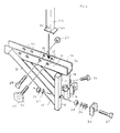
- Figure 2 is a partly exploded view of the coupling of Figure 1; and
- Figure 3 is a perspective view of the coupling and carrier of Figure 1.
-
- The
coupling 10 of the invention comprises a mainelongate element 12 in the form of a U-shaped profile. A shortcylindrical tube 14 is attached to the underside of theU-shaped profile 12 at one end, which is the front end in use. An upright 16 in the form of a square section tube is connected to each side of thecylindrical part 14 to each side of the U-shapedprofile 12. Astrut 18 extends from the lower end of each upright 16 to the opposite end of theU-shaped profile 12. Theparts - A
foot 20 in the form of a metal U-shaped profile is bolted to each upright 16 by means of abolt 22 which passes through the U-shapedfoot 20, through a plurality of washers 24 and anut 26, through opposed apertures in the tubular upright 16, through a further washer 24 and into anut 32. The open channel defined by each U-shapedfoot 20 faces forwards. - The
cylindrical part 14 includes in its wall adjacent its front lower edge two spaced threaded apertures 33 which receivebolts 34, and in its wall adjacent its rear lower edge includes two spaced plainwalled apertures 30. - Each
upstanding wall 36 of the U-shapedprofile 12 includes four longitudinally spacedapertures cylindrical part 14 and the connection to thestruts 18. The assembly includes avertical post 42 in the form of a square section tube. Thevertical post 42 has afoot plate 44 across its lower end. The lower end of thevertical post 42 is arranged to be received in the channel of the U-shapedprofile 12 and includes anaperture 46 to be aligned with one of the pairs ofapertures bolt 48 having alarge head 50 so that it can be manually screwed through theapertures vertical post 42 there is asteel rod 52. Eachsteel rod 52 is bent in two places and connected to thevertical post 42 at top and bottom. The twoloops 52 together form a trapezium shape. - The assembly also includes a
carrying base 53 attached to thecoupling 10. Thecarrying base 52 consists of amain beam 54 andcross beams 56. - The
main beam 54 is in the form of a square section tube which is slidable in the U-shapedprofile 12 of thecoupling 10. Thebeam 54 includes a pair of opposed apertures (not shown) to receive abolt 58. Thebolt 58 also passes through the next pair ofapertures profile 12 behind theapertures vertical post 42 by means of thebolt 48. Thebolt 58 is secured by anut 60 to secure themain beam 54. Thecross beams 56 are perpendicular to themain beam 54. Thecross beams 56 are equally spaced along themain beam 54 being welded to the upper surface thereof at their mid points. Eachcross beam 56 mounts twoloops 62, one to each side of themain beam 54. Twoend pieces 64 are provided. Eachend piece 64 mounts four equally spacedsockets 66 to receive the ends of thecross beams 56 on one side. - A tall U-shaped
part 68 has legs the ends of which are received in sockets mounted one to each side of themain beam 54 so that the U-shaped part stands upright midway along themain beam 54. - Fig 1 shows a
vehicle 70 which has atow hitch 72. Thetow hitch 72 has aneck 74 leading from amounting plate 76 to aball 78. Themounting plate 76 of thetow hitch 72 is secured to the vehicle by twobolts 80, one to each side of theplate 76. In use, thecoupling 10 is dropped onto thetow ball 78 of thevehicle 70 as shown in Fig 1 so that thecylindrical tube 14 of thecoupling 10 receives thetow ball 78 and thefeet 20 locate on the heads of thetow hitch bolts 80 which are received in the channels of the U-shapedfeet 20. This stably mounts thecoupling 10. The washers 24 can be arranged on eachbolt 22 on either side of the upright 16 to adjust the position of theU-shaped foot 20 in relation to the upright 16 and thereby facilitate an exactly horizontal mounting position for theelongate element 12 of thecoupling 10. Thebolts 34 are tightened into the threaded apertures 33 so that they protrude into thecylindrical tube 14 below theball 78 to prevent removal of thecoupling 10 from thevehicle 70. A padlock (not shown) can be placed through the two plainwalled apertures 30 in thecylindrical tube 14. The padlock hasp will lie below thetow ball 78 to prevent theft of thecoupling 10 and carryingbase 53. Thevehicle 70 has aspare wheel 82 mounted on itstailgate 84. For that reason, the set ofapertures 40 in theprofile 12 which are further from thecylindrical tube 14 are chosen for mounting themain tube 54 of thecarrier base 53 and thevertical post 42. Thoseparts bolts carrier base 53 in the horizontal position as shown, bicycles can be carried. The bicycles are placed with a wheel in eachloop 62 of one of thecross pieces 56 and can be strapped to thetall part 68 or thevertical post 42 or itsrods 52. When not in use, thecarrier base 53 can be pivotted about thebolt 58 to lie parallel to thevertical post 42 and can be secured thereto by a catch (not shown). - The
coupling 10 can equally be used on a vehicle which does not have a spare wheel on the back and in that case theapertures 38 in theprofile 12 which are closer to thecylindrical tube 14 would be used, to reduce the cantilever force on the tow hitch and reduce the overall length of the vehicle and coupling.
Claims (11)
- A coupling for mounting an item such as a bicycle carrier on to a vehicle, the coupling having means for removably mounting the coupling to a vehicle, and two means for mounting an item, the first item mounting means being arranged to mount an item further from the means for mounting to a vehicle than the second item mounting means.
- A coupling as claimed in claim 1, in which the means for removably mounting the coupling to a vehicle is arranged to mount the coupling to a tow ball of a vehicle.
- A coupling as claimed in claim 2, further comprising at least one recessed part which in use engages with a tow ball hitch bolt associated with a tow ball.
- A coupling as claimed in claim 3, in which the distance between the recessed part and another part of the coupling is adjustable.
- A coupling as claimed in claim 2, 3 or 4, in which the coupling includes a main elongate element, means to receive a tow ball connected to one end of the main elongate element, and a strut between the tow ball receiving means and the main elongate element.
- A coupling as claimed in claim 5, in which at least one of the first and second means for mounting an item is on the main elongate element between the connection to the strut and the connection to the tow ball receiving means.
- A coupling as claimed in claim 6, in which both the first and second means for mounting an item are between the connection to the strut and the connection to the tow ball receiving means.
- The combination of a coupling according to any preceding claim and a carrier.
- A combination as claimed in claim 8, further comprising a carrying base which is pivotally mounted to the coupling by the item mounting means so as to be pivotable between a generally horizontal use position and a generally vertical storage position.
- A combination as claimed in claim 9, further comprising a vertical frame, the carrying base being arranged to be attached to the vertical frame in the storage position.
- A combination as claimed in claim 10, in which two means for mounting the vertical frame are included, the first vertical frame mounting means being arranged further from the means for mounting to a vehicle than the second vertical frame mounting means.
Applications Claiming Priority (2)
| Application Number | Priority Date | Filing Date | Title |
|---|---|---|---|
| GB0028882 | 2000-11-27 | ||
| GB0028882A GB2369335B (en) | 2000-11-27 | 2000-11-27 | A coupling and the combination of a coupling and a carrier |
Publications (2)
| Publication Number | Publication Date |
|---|---|
| EP1209033A1 true EP1209033A1 (en) | 2002-05-29 |
| EP1209033B1 EP1209033B1 (en) | 2004-12-08 |
Family
ID=9903947
Family Applications (1)
| Application Number | Title | Priority Date | Filing Date |
|---|---|---|---|
| EP01307972A Expired - Lifetime EP1209033B1 (en) | 2000-11-27 | 2001-09-19 | A coupling for a vehicle load carrier |
Country Status (4)
| Country | Link |
|---|---|
| EP (1) | EP1209033B1 (en) |
| AT (1) | ATE284324T1 (en) |
| DE (1) | DE60107643T2 (en) |
| GB (1) | GB2369335B (en) |
Cited By (2)
| Publication number | Priority date | Publication date | Assignee | Title |
|---|---|---|---|---|
| GB2393430A (en) * | 2002-09-02 | 2004-03-31 | Eurotech Leisure Ltd | Cargo carrying apparatus |
| EP4201714A1 (en) * | 2021-12-24 | 2023-06-28 | King Rack Industrial Co., Ltd. | Securing device for hitch ball receiver |
Citations (5)
| Publication number | Priority date | Publication date | Assignee | Title |
|---|---|---|---|---|
| US4989765A (en) * | 1989-10-27 | 1991-02-05 | Huebner Jerry J | Vehicular carrier apparatus |
| US5460304A (en) * | 1993-10-05 | 1995-10-24 | Porter; Lawrence T. | Modular vehicular carrier system |
| US5850959A (en) * | 1994-04-14 | 1998-12-22 | Thomas S. Miller | Multifarious, vehicle cargo carrier system |
| GB2337236A (en) | 1998-05-05 | 1999-11-17 | Harry Edward Hurst | Carrier attachment for tow ball |
| US6006973A (en) * | 1996-10-28 | 1999-12-28 | Draw-Tite, Inc. | Hitch mounted cargo carrier bike rack adapter |
Family Cites Families (6)
| Publication number | Priority date | Publication date | Assignee | Title |
|---|---|---|---|---|
| GB2255943B (en) * | 1991-05-22 | 1995-03-22 | Smith Edwin William | Improvements in or relating to carriers |
| GB2258200A (en) * | 1991-08-01 | 1993-02-03 | Vessey Macpherson Ewan Callam | A luggage rack |
| US5549231A (en) * | 1994-01-24 | 1996-08-27 | Fletcher; James D. | Bicycle carrier for motor vehicles |
| US5469997A (en) * | 1994-09-13 | 1995-11-28 | Carlson; David C. | Multi-bicycle rear mounting bicycle rack |
| EP0710587A1 (en) * | 1994-11-07 | 1996-05-08 | Maximillian Edward Burgess | Rack |
| US5845832A (en) * | 1997-09-18 | 1998-12-08 | Eichmann; Marty W. | Rear-mounted vehicle cargo carrier |
-
2000
- 2000-11-27 GB GB0028882A patent/GB2369335B/en not_active Expired - Fee Related
-
2001
- 2001-09-19 AT AT01307972T patent/ATE284324T1/en not_active IP Right Cessation
- 2001-09-19 EP EP01307972A patent/EP1209033B1/en not_active Expired - Lifetime
- 2001-09-19 DE DE60107643T patent/DE60107643T2/en not_active Expired - Fee Related
Patent Citations (5)
| Publication number | Priority date | Publication date | Assignee | Title |
|---|---|---|---|---|
| US4989765A (en) * | 1989-10-27 | 1991-02-05 | Huebner Jerry J | Vehicular carrier apparatus |
| US5460304A (en) * | 1993-10-05 | 1995-10-24 | Porter; Lawrence T. | Modular vehicular carrier system |
| US5850959A (en) * | 1994-04-14 | 1998-12-22 | Thomas S. Miller | Multifarious, vehicle cargo carrier system |
| US6006973A (en) * | 1996-10-28 | 1999-12-28 | Draw-Tite, Inc. | Hitch mounted cargo carrier bike rack adapter |
| GB2337236A (en) | 1998-05-05 | 1999-11-17 | Harry Edward Hurst | Carrier attachment for tow ball |
Cited By (2)
| Publication number | Priority date | Publication date | Assignee | Title |
|---|---|---|---|---|
| GB2393430A (en) * | 2002-09-02 | 2004-03-31 | Eurotech Leisure Ltd | Cargo carrying apparatus |
| EP4201714A1 (en) * | 2021-12-24 | 2023-06-28 | King Rack Industrial Co., Ltd. | Securing device for hitch ball receiver |
Also Published As
| Publication number | Publication date |
|---|---|
| DE60107643D1 (en) | 2005-01-13 |
| GB0028882D0 (en) | 2001-01-10 |
| ATE284324T1 (en) | 2004-12-15 |
| EP1209033B1 (en) | 2004-12-08 |
| GB2369335B (en) | 2004-02-11 |
| DE60107643T2 (en) | 2005-11-10 |
| GB2369335A (en) | 2002-05-29 |
Similar Documents
| Publication | Publication Date | Title |
|---|---|---|
| US4646952A (en) | Method and apparatus for carrying a load with a motor vehicle | |
| US4938399A (en) | Article carrier | |
| US6095387A (en) | Multipurpose carrier | |
| US9333822B1 (en) | Trailer hitch attachment system with multiple receivers | |
| US5224636A (en) | Utility rack | |
| US7458597B2 (en) | Multiple use adjustable security trailer for transportation, storage and housing | |
| US5647153A (en) | Universal snow plow mounting frame assembly | |
| US5433357A (en) | Load carrying vehicle accessory | |
| US6164508A (en) | Vehicle rack systems and methods | |
| US6851695B2 (en) | Base rail kit for motor vehicle | |
| US4869521A (en) | Collapsible towing hitch | |
| US20060053667A1 (en) | Vehicle flag holder | |
| US10166932B2 (en) | Bicycle mount device | |
| GB2197273A (en) | Article carrying device for a vehicle | |
| US20050179241A1 (en) | Latching rack system for vehicles | |
| US9745006B2 (en) | Upright receiver assembly for attachment to trailer and methods of use | |
| US10576902B2 (en) | Cargo carrier system | |
| WO1982000119A1 (en) | Carrying device at vehicles | |
| US8430286B1 (en) | Boat carrying rack for use on transporting vehicles | |
| EP1209033B1 (en) | A coupling for a vehicle load carrier | |
| CA2669623A1 (en) | Adjustable hunting stand | |
| US20100133860A1 (en) | Carrier Support for Attaching to a Motor Vehicle | |
| US20090115209A1 (en) | Carrier Support for Attaching to a Motor Vehicle | |
| EP0721860A1 (en) | Bicycle carrier | |
| WO2003064214A1 (en) | A bike rack |
Legal Events
| Date | Code | Title | Description |
|---|---|---|---|
| PUAI | Public reference made under article 153(3) epc to a published international application that has entered the european phase |
Free format text: ORIGINAL CODE: 0009012 |
|
| AK | Designated contracting states |
Kind code of ref document: A1 Designated state(s): AT BE CH CY DE DK ES FI FR GB GR IE IT LI LU MC NL PT SE TR |
|
| AX | Request for extension of the european patent |
Free format text: AL;LT;LV;MK;RO;SI |
|
| 17P | Request for examination filed |
Effective date: 20020516 |
|
| AKX | Designation fees paid |
Designated state(s): AT BE CH CY DE DK ES FI FR GB GR IE IT LI LU MC NL PT SE TR |
|
| 17Q | First examination report despatched |
Effective date: 20030624 |
|
| GRAP | Despatch of communication of intention to grant a patent |
Free format text: ORIGINAL CODE: EPIDOSNIGR1 |
|
| GRAS | Grant fee paid |
Free format text: ORIGINAL CODE: EPIDOSNIGR3 |
|
| RBV | Designated contracting states (corrected) |
Designated state(s): AT BE CH CY DE DK ES FI FR GR IE IT LI LU MC NL PT SE TR |
|
| GRAA | (expected) grant |
Free format text: ORIGINAL CODE: 0009210 |
|
| AK | Designated contracting states |
Kind code of ref document: B1 Designated state(s): AT BE CH CY DE DK ES FI FR GR IE IT LI LU MC NL PT SE TR |
|
| PG25 | Lapsed in a contracting state [announced via postgrant information from national office to epo] |
Ref country code: TR Free format text: LAPSE BECAUSE OF FAILURE TO SUBMIT A TRANSLATION OF THE DESCRIPTION OR TO PAY THE FEE WITHIN THE PRESCRIBED TIME-LIMIT Effective date: 20041208 Ref country code: FI Free format text: LAPSE BECAUSE OF FAILURE TO SUBMIT A TRANSLATION OF THE DESCRIPTION OR TO PAY THE FEE WITHIN THE PRESCRIBED TIME-LIMIT Effective date: 20041208 |
|
| REG | Reference to a national code |
Ref country code: CH Ref legal event code: EP |
|
| REG | Reference to a national code |
Ref country code: IE Ref legal event code: FG4D |
|
| REF | Corresponds to: |
Ref document number: 60107643 Country of ref document: DE Date of ref document: 20050113 Kind code of ref document: P |
|
| PG25 | Lapsed in a contracting state [announced via postgrant information from national office to epo] |
Ref country code: GR Free format text: LAPSE BECAUSE OF FAILURE TO SUBMIT A TRANSLATION OF THE DESCRIPTION OR TO PAY THE FEE WITHIN THE PRESCRIBED TIME-LIMIT Effective date: 20050308 Ref country code: DK Free format text: LAPSE BECAUSE OF FAILURE TO SUBMIT A TRANSLATION OF THE DESCRIPTION OR TO PAY THE FEE WITHIN THE PRESCRIBED TIME-LIMIT Effective date: 20050308 |
|
| PG25 | Lapsed in a contracting state [announced via postgrant information from national office to epo] |
Ref country code: ES Free format text: LAPSE BECAUSE OF FAILURE TO SUBMIT A TRANSLATION OF THE DESCRIPTION OR TO PAY THE FEE WITHIN THE PRESCRIBED TIME-LIMIT Effective date: 20050319 |
|
| REG | Reference to a national code |
Ref country code: SE Ref legal event code: TRGR |
|
| RAP2 | Party data changed (patent owner data changed or rights of a patent transferred) |
Owner name: STOKES, NIGEL DERRICK |
|
| RIN2 | Information on inventor provided after grant (corrected) |
Inventor name: WRIGHT, RICHARD |
|
| REG | Reference to a national code |
Ref country code: CH Ref legal event code: PUE Owner name: NIGEL DERRICK STOKES Free format text: WRIGHT, RICHARD#SOUTHAM ROAD, UFTON#LEAMINGTON SPA CV33 9PF (GB) -TRANSFER TO- NIGEL DERRICK STOKES#CHURCH FARM HOUSE, OLD MILVERTON#LEAMINGTON SPA CV32 6SA (GB) Ref country code: CH Ref legal event code: NV Representative=s name: KELLER & PARTNER PATENTANWAELTE AG |
|
| PGFP | Annual fee paid to national office [announced via postgrant information from national office to epo] |
Ref country code: IE Payment date: 20050822 Year of fee payment: 5 |
|
| PGFP | Annual fee paid to national office [announced via postgrant information from national office to epo] |
Ref country code: SE Payment date: 20050826 Year of fee payment: 5 |
|
| PGFP | Annual fee paid to national office [announced via postgrant information from national office to epo] |
Ref country code: FR Payment date: 20050831 Year of fee payment: 5 |
|
| RIN2 | Information on inventor provided after grant (corrected) |
Inventor name: WRIGHT, RICHARD |
|
| NLT2 | Nl: modifications (of names), taken from the european patent patent bulletin |
Owner name: STOKES, NIGEL DERRICK Effective date: 20050720 |
|
| PGFP | Annual fee paid to national office [announced via postgrant information from national office to epo] |
Ref country code: BE Payment date: 20050909 Year of fee payment: 5 |
|
| PGFP | Annual fee paid to national office [announced via postgrant information from national office to epo] |
Ref country code: DE Payment date: 20050915 Year of fee payment: 5 |
|
| PGFP | Annual fee paid to national office [announced via postgrant information from national office to epo] |
Ref country code: CH Payment date: 20050916 Year of fee payment: 5 |
|
| PG25 | Lapsed in a contracting state [announced via postgrant information from national office to epo] |
Ref country code: CY Free format text: LAPSE BECAUSE OF FAILURE TO SUBMIT A TRANSLATION OF THE DESCRIPTION OR TO PAY THE FEE WITHIN THE PRESCRIBED TIME-LIMIT Effective date: 20050919 |
|
| PGFP | Annual fee paid to national office [announced via postgrant information from national office to epo] |
Ref country code: AT Payment date: 20050919 Year of fee payment: 5 |
|
| PG25 | Lapsed in a contracting state [announced via postgrant information from national office to epo] |
Ref country code: MC Free format text: LAPSE BECAUSE OF NON-PAYMENT OF DUE FEES Effective date: 20050930 Ref country code: LU Free format text: LAPSE BECAUSE OF NON-PAYMENT OF DUE FEES Effective date: 20050930 |
|
| PGFP | Annual fee paid to national office [announced via postgrant information from national office to epo] |
Ref country code: NL Payment date: 20050930 Year of fee payment: 5 |
|
| NLS | Nl: assignments of ep-patents |
Owner name: STOKES, NIGEL DERRICK Effective date: 20050719 |
|
| REG | Reference to a national code |
Ref country code: FR Ref legal event code: TP |
|
| PLBE | No opposition filed within time limit |
Free format text: ORIGINAL CODE: 0009261 |
|
| STAA | Information on the status of an ep patent application or granted ep patent |
Free format text: STATUS: NO OPPOSITION FILED WITHIN TIME LIMIT |
|
| 26N | No opposition filed |
Effective date: 20050909 |
|
| ET | Fr: translation filed | ||
| PG25 | Lapsed in a contracting state [announced via postgrant information from national office to epo] |
Ref country code: IE Free format text: LAPSE BECAUSE OF NON-PAYMENT OF DUE FEES Effective date: 20060919 Ref country code: AT Free format text: LAPSE BECAUSE OF NON-PAYMENT OF DUE FEES Effective date: 20060919 |
|
| PG25 | Lapsed in a contracting state [announced via postgrant information from national office to epo] |
Ref country code: SE Free format text: LAPSE BECAUSE OF NON-PAYMENT OF DUE FEES Effective date: 20060920 |
|
| PG25 | Lapsed in a contracting state [announced via postgrant information from national office to epo] |
Ref country code: LI Free format text: LAPSE BECAUSE OF NON-PAYMENT OF DUE FEES Effective date: 20060930 Ref country code: CH Free format text: LAPSE BECAUSE OF NON-PAYMENT OF DUE FEES Effective date: 20060930 Ref country code: BE Free format text: LAPSE BECAUSE OF NON-PAYMENT OF DUE FEES Effective date: 20060930 |
|
| PGFP | Annual fee paid to national office [announced via postgrant information from national office to epo] |
Ref country code: IT Payment date: 20060930 Year of fee payment: 6 |
|
| PG25 | Lapsed in a contracting state [announced via postgrant information from national office to epo] |
Ref country code: NL Free format text: LAPSE BECAUSE OF NON-PAYMENT OF DUE FEES Effective date: 20070401 |
|
| PG25 | Lapsed in a contracting state [announced via postgrant information from national office to epo] |
Ref country code: DE Free format text: LAPSE BECAUSE OF NON-PAYMENT OF DUE FEES Effective date: 20070403 |
|
| REG | Reference to a national code |
Ref country code: CH Ref legal event code: PL |
|
| EUG | Se: european patent has lapsed | ||
| NLV4 | Nl: lapsed or anulled due to non-payment of the annual fee |
Effective date: 20070401 |
|
| REG | Reference to a national code |
Ref country code: IE Ref legal event code: MM4A |
|
| REG | Reference to a national code |
Ref country code: FR Ref legal event code: ST Effective date: 20070531 |
|
| BERE | Be: lapsed |
Owner name: *STOKES NIGEL DERRICK Effective date: 20060930 |
|
| PG25 | Lapsed in a contracting state [announced via postgrant information from national office to epo] |
Ref country code: PT Free format text: LAPSE BECAUSE OF NON-PAYMENT OF DUE FEES Effective date: 20050508 |
|
| PG25 | Lapsed in a contracting state [announced via postgrant information from national office to epo] |
Ref country code: FR Free format text: LAPSE BECAUSE OF NON-PAYMENT OF DUE FEES Effective date: 20061002 |
|
| PG25 | Lapsed in a contracting state [announced via postgrant information from national office to epo] |
Ref country code: IT Free format text: LAPSE BECAUSE OF NON-PAYMENT OF DUE FEES Effective date: 20070919 |