EP1209010A1 - Dispositif de fixation d'un amortisseur de suspension d'un véhicule automobile - Google Patents
Dispositif de fixation d'un amortisseur de suspension d'un véhicule automobile Download PDFInfo
- Publication number
- EP1209010A1 EP1209010A1 EP01403012A EP01403012A EP1209010A1 EP 1209010 A1 EP1209010 A1 EP 1209010A1 EP 01403012 A EP01403012 A EP 01403012A EP 01403012 A EP01403012 A EP 01403012A EP 1209010 A1 EP1209010 A1 EP 1209010A1
- Authority
- EP
- European Patent Office
- Prior art keywords
- annular block
- bell
- rod
- wall
- annular
- Prior art date
- Legal status (The legal status is an assumption and is not a legal conclusion. Google has not performed a legal analysis and makes no representation as to the accuracy of the status listed.)
- Granted
Links
- 239000000725 suspension Substances 0.000 title claims description 7
- 230000035939 shock Effects 0.000 claims description 39
- 239000006096 absorbing agent Substances 0.000 claims description 37
- 230000002093 peripheral effect Effects 0.000 claims description 11
- 238000003466 welding Methods 0.000 claims description 9
- 239000013536 elastomeric material Substances 0.000 claims description 3
- 230000001681 protective effect Effects 0.000 claims description 3
- 229920001971 elastomer Polymers 0.000 abstract description 3
- 239000000806 elastomer Substances 0.000 abstract description 3
- 238000001914 filtration Methods 0.000 abstract 2
- 230000000284 resting effect Effects 0.000 description 3
- 239000002184 metal Substances 0.000 description 2
- 238000005452 bending Methods 0.000 description 1
- 230000000903 blocking effect Effects 0.000 description 1
- 230000006835 compression Effects 0.000 description 1
- 238000007906 compression Methods 0.000 description 1
- 238000006073 displacement reaction Methods 0.000 description 1
- 239000006260 foam Substances 0.000 description 1
- 238000009413 insulation Methods 0.000 description 1
- 238000012423 maintenance Methods 0.000 description 1
- 239000000463 material Substances 0.000 description 1
- 230000010355 oscillation Effects 0.000 description 1
- 230000035515 penetration Effects 0.000 description 1
- 229920002635 polyurethane Polymers 0.000 description 1
- 239000004814 polyurethane Substances 0.000 description 1
- 230000036316 preload Effects 0.000 description 1
Images

Classifications
-
- F—MECHANICAL ENGINEERING; LIGHTING; HEATING; WEAPONS; BLASTING
- F16—ENGINEERING ELEMENTS AND UNITS; GENERAL MEASURES FOR PRODUCING AND MAINTAINING EFFECTIVE FUNCTIONING OF MACHINES OR INSTALLATIONS; THERMAL INSULATION IN GENERAL
- F16F—SPRINGS; SHOCK-ABSORBERS; MEANS FOR DAMPING VIBRATION
- F16F9/00—Springs, vibration-dampers, shock-absorbers, or similarly-constructed movement-dampers using a fluid or the equivalent as damping medium
- F16F9/32—Details
- F16F9/54—Arrangements for attachment
-
- B—PERFORMING OPERATIONS; TRANSPORTING
- B60—VEHICLES IN GENERAL
- B60G—VEHICLE SUSPENSION ARRANGEMENTS
- B60G13/00—Resilient suspensions characterised by arrangement, location or type of vibration dampers
- B60G13/001—Arrangements for attachment of dampers
- B60G13/003—Arrangements for attachment of dampers characterised by the mounting on the vehicle body or chassis of the damper unit
Definitions
- the present invention relates to a device for attachment of a vehicle suspension shock absorber automobile.
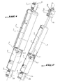
- FIGs 1 and 2 show in perspective with partial pullout two types of shock absorbers known hydraulics used in particular in trains rear of motor vehicles.
- Each of these two shock absorbers includes a cylinder 1 and a rod 2 slidably mounted in the cylinder 1 to drive therein a piston 3 delimiting two rooms and which pushes into them oil in nozzles calibrated 6 according to the direction of displacement of the rod to brake, more or less energetically, the oscillations of the suspension.
- the rod 2 is connected to the vehicle chassis by a hinge elastic 7 in the form of a cylindrical elastomer sleeve fixed by adhesion in a socket or metal eye 8 secured to the end of the rod by welding or by screwing, an axis not shown crossing the joint elastic 7 to secure the end of the rod 2 to the vehicle chassis.
- the shock body 1 is connected to the wheel spindle support by an articulation elastic 9 also in the form of an elastomer sleeve fixed by adhesion in a socket or metal eye 10 secured to the end of the shock absorber cylinder 1, an axis (not shown) passing through the sleeve 9 for fix the articulation to the wheel stub support.
- the rod shock absorber 2 is connected to the vehicle body by an elastic joint comprising two blocks elastomeric elastics 11 enclosing a rigid part plane (not shown) of the body or which is integral of it by welding or screwing.
- the two blocks elastic bands 11 are compressed on either side of the rigid flat part between two upper cups and lower 12 close to each other by a nut and lock nut assembly 13 screwed to the end free threaded damper rod 2 passing through coaxially the blocks 11 and the cups 12, the lower cup 12 being supported on a shoulder of rod 2.
- the nut and lock nut assembly 13 and the cups 12 ensure the maintenance of a preload of elastic blocks 11.
- the shock body 1 is connected to the wheel spindle support like that of the Figure 1.
- fixing the shock absorber body 1 to the wheel stub support can also be performed from identical to rod 2, i.e. by a stud secured, by welding, to the bottom 1a of the body 1 coaxial with the latter and compressing two blocks elastic on either side of a flat rigid part secured to this support by two opposing cups and a nut and lock nut assembly screwed to the stud.
- the object of the present invention is to eliminate the above drawback of known shock absorbers offering a shock absorber whose overall length is substantially reduced.
- the device for attachment of a vehicle suspension shock absorber automobile whereby the end of the rod or shock absorber cylinder is connected to the body of the vehicle by means of an elastic joint using a filter element made of elastomeric material, is characterized in that the filter element comprises a block annular concentrically surrounding the part end of rod or cylinder to be connected at the checkout by being attached to the checkout by a rigid support means and on the other hand connected to this end part by means trapping the block annular by compressing it axially.
- the means ring block imprisonment include one piece forming a bell integral with the rod so that the side wall of the bell-shaped part surrounds concentrically the rod, and a rigid circular plate integral with the transverse wall of the shaped part bell and protruding from the side wall of this last to delimit with the opposite wall shaped flange of the bell-shaped part a housing of reception of the annular block, the rigid circular wall and the collar-shaped wall of the shaped part of bell being spaced apart from each other by a distance less than the axial thickness of the annular block.
- the annular block is supported on the wall side of the bell-shaped piece and has two upper and lower annular recesses adjacent to this side wall to reduce the conical rigidity of the annular block.
- the bell-shaped part and the rigid plate circular are fixed together on top of each other at the end of the damper rod going through two holes in the circular plate and the transverse wall of the bell-shaped part in support on a shoulder of the shock absorber rod.
- the rigid circular plate and the wall cross of the bell-shaped part are fixed by a tightening nut screwed to the threaded end of the shock absorber rod.
- the rigid plate circular and the transverse wall of the shaped part of bell are fixed by welding of the circular plate at the end of the damper rod and that is disposed above this transverse wall.
- a protective sleeve coaxially surrounding the shock absorber cylinder is embedded in one of its ends around the outer peripheral edge of the flange-shaped wall of the shaped part bell.
- the means for imprisoning the annular block include a cylindrical sleeve fixed by welding on the periphery of the end part of the damper cylinder and of which one end has a wall in the form of a collar, and a crown-shaped cross plate surrounding concentrically the cylindrical sleeve in the vicinity of its opposite end while resting on the block annular so as to prestress it axially in the housing defined by the side wall of the sleeve, the rim-shaped wall and the transverse plate in crown shape.
- the crown-shaped plate is engaged in support on the annular block by an outer folded edge of the cylindrical sleeve resting on the plate in the form of crowned.
- the annular block is supported on the wall side of the cylindrical sleeve and has two upper and lower annular recesses adjacent to this side wall to reduce the conical rigidity of the annular block.
- the support means of the annular block comprises a annular plate fixed on the one hand to the vehicle body and on the other hand to the annular block concentrically to this last by embedding its internal peripheral edge in the annular block.
- the annular block is adhered to the peripheral edge internal of the annular plate for fixing this block.
- the internal peripheral edge of the annular plate is extended by a frustoconical part with radially internal rim embedded in the annular block and directed towards the end of the damper rod or towards the bottom wall of the damper body.
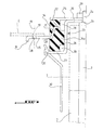
- the shock absorber of a suspension of a motor vehicle comprises a cylinder 1 of which the lower end (not shown) is fixed, by an elastic joint, to a wheel stub support rear and a rod 2 slidably mounted in the cylinder 1 and the upper end of which is connected to the body C of the vehicle via a elastic joint using a filter element 14 made of elastomeric material.
- the filter element 14 is formed by an annular block arranged so as to surround concentrically the end part of the rod 2 to be connected to the cash register.
- the annular block 14 is fixed to the box C by a rigid support means comprising a cup-shaped annular plate 15 with rim 16 increases the bending stiffness of the plate 15 which is fixed to the body C by fixing means symbolized by axis 17 passing through holes correspondents 18, 19 of plate 15 and of body C and which provide a permanent link, such as by example of rivets, or removable, such as screws fixation.
- the fixing plate 15 is integral with the block 14 concentrically and transversely to it by its internal peripheral edge 20 fitting into block 14 by being united by adhesion.
- the edge device 20 of the fixing plate 15 is extended by a rigid frustoconical part 21 directed towards the end of the damper rod 2 and comprising a radially internal annular rim 22.
- the part tapered 21 and flange 22 are embedded in the block annular 14 which is adhered to them.
- the annular block 14 is further connected to the part end of the rod 2 by means of imprisonment which include a bell-shaped piece 23 integral of the damper rod 2 so that its side wall cylindrical 24 concentrically surrounds this rod, and a rigid circular transverse plate 25 integral with the end of the rod 2 above the wall transverse 26 of the bell-shaped part 23 in protruding from the side wall 24 of the latter of so as to delimit with the opposite wall 27 in the form of flange of the bell-shaped part 23 a housing for receiving the annular block 14.
- the transverse plate 25 and the flange-shaped wall 27 are spaced one above the other by a distance less than the thickness in the axial direction, parallel to the rod 2, of the annular block 14 so as to exert an effort of axial compression on the annular block 14 and the maintain in the housing defined by the plate 25, the transverse wall and side wall 24 of the workpiece bell-shaped 23, the block 14 also being supported on the side wall 24 of the part 23.
- Block 14 includes two annular recesses upper and lower 28 adjacent to the side wall 24 of room 23 being located on either side of the central annular part 14a of the block 14 contacting the side wall 24.
- the transverse plate 25 and the transverse wall 26 of the part 23 are fixed one on the other at the end of the rod 2 by a nut blocking 29 screwed to the threaded free end 2a of the rod 2, the transverse wall 26 of the part 23 being maintained in abutment on a shoulder 2b of the rod 2.
- the plate 25 and the transverse wall 26 of the part 3 can be fixed one on the other to the rod 2 by welding the plate 25 at the free end 2a of the rod 2.
- Figure 3 shows the presence of a protection 30 of the concentrically surrounding damper this one and whose upper end part is recessed around the periphery of the outer peripheral edge of the flange-shaped wall 27 of the bell-shaped part 23.
- the upper part of the protective sleeve 30 has a radially internal groove 31 in which forcibly engages the outer peripheral edge of the transverse wall 27 of the bell-shaped part 23.
- Figure 4 shows an alternative embodiment of the articulation of the invention used to connect the end part of shock absorber cylinder 1 to vehicle body C instead of fixing the shock absorber to the body by the shock absorber rod as described in figure 3.
- the housing of reception of the annular block 14 making it possible to trapping it includes a cylindrical sleeve 32 fixed by welding around the periphery of the end part 1a of the shock absorber cylinder 1 and delimited by its wall of bottom 1b opposite the end of the shock absorber rod (not shown) fixed in this case to a support wheel rocket.
- the means delimiting the housing of the annular block 14 further include a shaped cross plate crown 33 concentrically surrounding the sleeve 32 in the vicinity of its end portion located at the bottom wall 1b of the cylinder 1 and disposed parallel to a transverse wall in the form of flange of the end of the sleeve 32 opposite the cylinder wall 1b.
- annular block 14 is trapped in the housing defined by the sleeve 32, the wall in the form of flange 34 thereof and the transverse plate 33 with the distance separating the latter from the wall 34 less than the axial thickness of the annular block 14 for compress it axially.
- the crown plate 33 is held in abutment forced on the annular block 14 by a folded edge outer 35 of the sleeve 32 resting on the central part from plate 33.
- the annular block 14 includes the two recesses upper and lower annulars 28 located on either side on the other side of the central annular part 14a of this block in pressing on the corresponding face of the sleeve 32.
- the device for fixing a conforming shock absorber to the invention allows to substantially reduce the axial size of the shock absorber, which allows remove the intrusion of the shock absorber in the passage of matching wheel and lower the floor while allowing, if necessary, the use of a device bulky piloted depreciation. Furthermore, the fact that it is not necessary to provide a filter block and its fixing support having a symmetry of revolution, differentiate features stiffness of this filter block according to the different directions for better insulation performance vibrations. Increase in contact areas with the filter block allows the use of materials more flexible such as for example foam polyurethane with high performance potential in acoustic.
Landscapes
- Engineering & Computer Science (AREA)
- General Engineering & Computer Science (AREA)
- Mechanical Engineering (AREA)
- Vehicle Body Suspensions (AREA)
- Fluid-Damping Devices (AREA)
- Vibration Prevention Devices (AREA)
Abstract
Description
- les figures 1 et 2 sont des vues en perspective éclatées de deux types d'amortisseurs connus ;
- la figure 3 est une demi-vue partielle en coupe agrandie d'un amortisseur dont la tige est reliée à la caisse du véhicule par une articulation conforme à l'invention ; et
- la figure 4 est une demi-vue partielle agrandie d'un amortisseur dont le cylindre est relié à un support de fusée de roue par une articulation conforme à l'invention.
Claims (14)
- Dispositif de fixation d'un amortisseur de suspension d'un véhicule automobile, selon lequel l'extrémité de la tige (2) ou du cylindre (1) de l'amortisseur est reliée à la caisse (C) du véhicule par l'intermédiaire d'une articulation élastique utilisant un élément filtrant (14) en matériau élastomère, caractérisé en ce que l'élément filtrant (14) comprend un bloc annulaire entourant concentriquement la partie d'extrémité de la tige (2) ou du cylindre (1) devant être reliée à la caisse (C) en étant d'une part fixé à la caisse par un moyen de support rigide (15) et d'autre part relié à cette partie d'extrémité par des moyens (24,25,27; 32,33,34) emprisonnant le bloc annulaire (14) en le comprimant axialement.
- Dispositif selon la revendication 1, où l'extrémité de la tige d'amortisseur (2) est reliée à la caisse du véhicule, caractérisé en ce que les moyens d'emprisonnement du bloc annulaire comprennent une pièce en forme de cloche (23) solidaire de la tige (2) de façon que la paroi latérale (24) de la pièce en forme de cloche (23) entoure concentriquement la tige (2), et une plaque rigide circulaire (25) solidaire de la paroi transversale (26) de la pièce en forme de cloche (23) et débordant de la paroi latérale (24) de cette dernière pour délimiter avec la paroi opposée (27) en forme de collerette de la pièce en forme de cloche (23) un logement de réception du bloc annulaire (14), la paroi rigide circulaire (25) et la paroi en forme de collerette (27) de la pièce en forme de cloche (23) étant espacées l'une de l'autre d'une distance inférieure à l'épaisseur axiale du bloc annulaire (14).
- Dispositif selon la revendications 2, caractérisé en ce que le bloc annulaire (14) est en appui sur la paroi latérale (24) de la pièce en forme de cloche (23) et comporte deux évidements annulaires supérieure et inférieure (28) adjacents à cette paroi latérale pour diminuer la rigidité conique du bloc annulaire (14).
- Dispositif selon la revendication 2 ou 3, caractérisé en ce que la pièce en forme de cloche (23) et la plaque rigide circulaire (25) sont fixées ensemble l'une sur l'autre à l'extrémité de la tige d'amortisseur (2) traversant deux perçages respectivement de la plaque circulaire et de la paroi transversale (26) de la pièce en forme de cloche en appui sur un épaulement (2b) de la tige d'amortisseur (2).
- Dispositif selon la revendication 4, caractérisé en ce que la plaque circulaire (25) et la paroi transversale de la pièce en forme de cloche sont fixées par un écrou de serrage vissé à l'extrémité filetée de la tige d'amortisseur.
- Dispositif selon la revendication 4, caractérisé en ce que la plaque circulaire et la paroi transversale (26) de la pièce en forme de cloche (23) sont fixées par soudage de la plaque circulaire (25) à l'extrémité 2a de la tige d'amortisseur (2) et qui est disposée au-dessus de cette paroi transversale.
- Dispositif selon l'une des revendications 2 à 6, caractérisé en ce qu'un manchon de protection (30) entourant coaxialement le cylindre d'amortisseur (1) est encastré à l'une de ses extrémités sur le pourtour du bord périphérique externe de la paroi en forme de collerette (27) de la pièce en forme de cloche (23).
- Dispositif selon la revendication 1, où la partie d'extrémité du cylindre d'amortisseur (1) est reliée à la caisse (C) du véhicule, caractérisé en ce que les moyens d'emprisonnement du bloc annulaire (14) comprennent un manchon cylindrique (32) fixé par soudage sur le pourtour de la partie d'extrémité du cylindre d'amortisseur (1) et dont une extrémité comporte une paroi en forme de collerette (34), et une plaque transversale en forme de couronne (33) entourant concentriquement le manchon cylindrique (32) au voisinage de son extrémité opposée en étant en appui sur le bloc annulaire (14) de façon à le précontraindre axialement dans le logement défini par la paroi latérale du manchon (32), la paroi en forme de collerette (34) et la plaque transversale en forme de couronne (33).
- Dispositif selon la revendication 8, caractérisé en ce que la plaque en forme de couronne (33) est engagée en appui sur le bloc annulaire (14) par un bord rabattu externe (35) du manchon cylindrique (32) en appui sur la plaque en forme de couronne (33).
- Dispositif selon la revendication 8 ou 9, caractérisé en ce que le bloc annulaire (14) est en appui sur la paroi latérale du manchon cylindrique (32) et comporte deux évidements annulaires supérieur et inférieur (28) adjacents à cette paroi latérale pour diminuer la rigidité conique du bloc annulaire.
- Dispositif selon l'une des revendications 2 à 10, caractérisé en ce que le moyen de support du bloc annulaire comprend une plaque annulaire (15) fixée d'une part à la caisse du véhicule et d'autre part au bloc annulaire (14) concentriquement à ce dernier par encastrement de son bord périphérique interne dans le bloc annulaire.
- Dispositif selon la revendication 11, caractérisé en ce que le bloc annulaire (14) est adhérisé au bord périphérique interne (20) de la plaque annulaire (15) de fixation du bloc annulaire.
- Dispositif selon la revendication 11 ou 12, caractérisé en ce que le bord périphérique interne (20) de la plaque annulaire (15) est prolongé par une partie tronconique (21) à rebord radialement interne (22) noyée dans le bloc annulaire (14) et dirigée vers l'extrémité de la tige d'amortisseur (2) ou vers la paroi de fond (1a) du corps d'amortisseur (1).
- Dispositif selon l'une des revendications 1 à 7, caractérisé en ce que le cylindre d'amortisseur (1) peut pénétrer dans la pièce en forme de cloche (23).
Applications Claiming Priority (2)
| Application Number | Priority Date | Filing Date | Title |
|---|---|---|---|
| FR0015212A FR2817199B1 (fr) | 2000-11-24 | 2000-11-24 | Dispositif de fixation d'un amortisseur de suspension d'un vehicule automobile |
| FR0015212 | 2000-11-24 |
Publications (2)
| Publication Number | Publication Date |
|---|---|
| EP1209010A1 true EP1209010A1 (fr) | 2002-05-29 |
| EP1209010B1 EP1209010B1 (fr) | 2004-08-11 |
Family
ID=8856853
Family Applications (1)
| Application Number | Title | Priority Date | Filing Date |
|---|---|---|---|
| EP01403012A Expired - Lifetime EP1209010B1 (fr) | 2000-11-24 | 2001-11-23 | Dispositif de fixation d'un amortisseur de suspension d'un véhicule automobile |
Country Status (5)
| Country | Link |
|---|---|
| EP (1) | EP1209010B1 (fr) |
| AT (1) | ATE273144T1 (fr) |
| DE (1) | DE60104801T2 (fr) |
| ES (1) | ES2225443T3 (fr) |
| FR (1) | FR2817199B1 (fr) |
Citations (3)
| Publication number | Priority date | Publication date | Assignee | Title |
|---|---|---|---|---|
| US4555096A (en) * | 1980-11-20 | 1985-11-26 | Ford Motor Company | Pneumatic spring and strut assembly |
| US4747587A (en) * | 1987-01-15 | 1988-05-31 | Chrysler Motors Corporation | Low profile suspension strut |
| FR2630507A1 (fr) * | 1988-04-22 | 1989-10-27 | Peugeot | Dispositif de fixation, notamment d'un amortisseur sur un vehicule automobile |
-
2000
- 2000-11-24 FR FR0015212A patent/FR2817199B1/fr not_active Expired - Fee Related
-
2001
- 2001-11-23 EP EP01403012A patent/EP1209010B1/fr not_active Expired - Lifetime
- 2001-11-23 AT AT01403012T patent/ATE273144T1/de not_active IP Right Cessation
- 2001-11-23 ES ES01403012T patent/ES2225443T3/es not_active Expired - Lifetime
- 2001-11-23 DE DE60104801T patent/DE60104801T2/de not_active Expired - Lifetime
Patent Citations (3)
| Publication number | Priority date | Publication date | Assignee | Title |
|---|---|---|---|---|
| US4555096A (en) * | 1980-11-20 | 1985-11-26 | Ford Motor Company | Pneumatic spring and strut assembly |
| US4747587A (en) * | 1987-01-15 | 1988-05-31 | Chrysler Motors Corporation | Low profile suspension strut |
| FR2630507A1 (fr) * | 1988-04-22 | 1989-10-27 | Peugeot | Dispositif de fixation, notamment d'un amortisseur sur un vehicule automobile |
Also Published As
| Publication number | Publication date |
|---|---|
| ATE273144T1 (de) | 2004-08-15 |
| EP1209010B1 (fr) | 2004-08-11 |
| DE60104801D1 (de) | 2004-09-16 |
| DE60104801T2 (de) | 2005-09-15 |
| FR2817199B1 (fr) | 2003-08-15 |
| ES2225443T3 (es) | 2005-03-16 |
| FR2817199A1 (fr) | 2002-05-31 |
Similar Documents
| Publication | Publication Date | Title |
|---|---|---|
| EP0352184B1 (fr) | Dispositif supérieur de liaison articulée entre un ensemble ressort-amortisseur et le châssis d'un véhicule automobile | |
| EP0126006B1 (fr) | Dispositif de liaison entre la structure d'un véhicule et une jambe de suspension | |
| EP1882601A1 (fr) | Butée de suspension et jambe de suspension pourvue d'une telle butée | |
| FR2812362A1 (fr) | Support antivibratoire hydraulique et son procede de fabrication | |
| FR2818718A1 (fr) | Manchon antivibratoire et vehicule automobile comportant un tel manchon | |
| WO2002006699A1 (fr) | Dispositif de limitation de course pour amortisseur de vehicule automobile, et procede de fabrication d'un tel dispositif | |
| EP4015262A1 (fr) | Jambe de force de suspension de vehicule | |
| EP0818639B1 (fr) | Dispositif antivibratoire hydraulique | |
| EP1120298A1 (fr) | Train avant pour véhicule automobile à lame de ressort transversale | |
| EP2428697A1 (fr) | Butee de suspension et jambe de suspension | |
| EP1209010B1 (fr) | Dispositif de fixation d'un amortisseur de suspension d'un véhicule automobile | |
| EP4015263B1 (fr) | Vehicule automobile | |
| FR2750190A1 (fr) | Amortisseur de vibrations, notamment pour des vehicules automobiles | |
| EP1378682A1 (fr) | Dispositif d'articulation hydroélastique à effet axial | |
| FR2787764A1 (fr) | Dispositif de suspension d'une charge utile dans un lanceur spatial | |
| EP1439320B1 (fr) | Support anti-vibratoire | |
| EP1508722B1 (fr) | Attache à ressort pneumatique, notamment pour suspension de véhicule automobile, et véhicule automobile équipe d'une telle attache | |
| FR2812242A1 (fr) | Essieu deformable a suspension integree pour vehicule automobile | |
| FR2898075A1 (fr) | Jante de roue d'un vehicule, notamment d'un vehicule automobile, equipe d'un dispositif d'amortissement | |
| FR3050403B1 (fr) | Dispositif de suspension d'une roue d'un vehicule | |
| EP3742018B1 (fr) | Support antivibratoire hydraulique | |
| EP3251879B1 (fr) | Systeme de suspension hydraulique d'une roue d'un vehicule | |
| EP0961887B1 (fr) | Dispositif elastique d'orientation radiale pour un volant amortisseur double de transmission de vehicule automobile | |
| FR2905157A1 (fr) | Dispositif de fixation superieure d'un amortisseur de suspension sur la caisse d'un vehicule. | |
| FR2811616A1 (fr) | Dispositif de butee de limitation de course pour amortisseur de vehicule automobile |
Legal Events
| Date | Code | Title | Description |
|---|---|---|---|
| PUAI | Public reference made under article 153(3) epc to a published international application that has entered the european phase |
Free format text: ORIGINAL CODE: 0009012 |
|
| AK | Designated contracting states |
Kind code of ref document: A1 Designated state(s): AT BE CH CY DE DK ES FI FR GB GR IE IT LI LU MC NL PT SE TR |
|
| AX | Request for extension of the european patent |
Free format text: AL;LT;LV;MK;RO;SI |
|
| 17P | Request for examination filed |
Effective date: 20021102 |
|
| AKX | Designation fees paid |
Designated state(s): AT BE CH CY DE DK ES FI FR GB GR IE IT LI LU MC NL PT SE TR |
|
| 17Q | First examination report despatched |
Effective date: 20030730 |
|
| GRAP | Despatch of communication of intention to grant a patent |
Free format text: ORIGINAL CODE: EPIDOSNIGR1 |
|
| GRAS | Grant fee paid |
Free format text: ORIGINAL CODE: EPIDOSNIGR3 |
|
| GRAA | (expected) grant |
Free format text: ORIGINAL CODE: 0009210 |
|
| AK | Designated contracting states |
Kind code of ref document: B1 Designated state(s): AT BE CH CY DE DK ES FI FR GB GR IE IT LI LU MC NL PT SE TR |
|
| PG25 | Lapsed in a contracting state [announced via postgrant information from national office to epo] |
Ref country code: NL Free format text: LAPSE BECAUSE OF FAILURE TO SUBMIT A TRANSLATION OF THE DESCRIPTION OR TO PAY THE FEE WITHIN THE PRESCRIBED TIME-LIMIT Effective date: 20040811 Ref country code: TR Free format text: LAPSE BECAUSE OF FAILURE TO SUBMIT A TRANSLATION OF THE DESCRIPTION OR TO PAY THE FEE WITHIN THE PRESCRIBED TIME-LIMIT Effective date: 20040811 Ref country code: FI Free format text: LAPSE BECAUSE OF FAILURE TO SUBMIT A TRANSLATION OF THE DESCRIPTION OR TO PAY THE FEE WITHIN THE PRESCRIBED TIME-LIMIT Effective date: 20040811 Ref country code: CY Free format text: LAPSE BECAUSE OF FAILURE TO SUBMIT A TRANSLATION OF THE DESCRIPTION OR TO PAY THE FEE WITHIN THE PRESCRIBED TIME-LIMIT Effective date: 20040811 Ref country code: AT Free format text: LAPSE BECAUSE OF FAILURE TO SUBMIT A TRANSLATION OF THE DESCRIPTION OR TO PAY THE FEE WITHIN THE PRESCRIBED TIME-LIMIT Effective date: 20040811 Ref country code: IE Free format text: LAPSE BECAUSE OF FAILURE TO SUBMIT A TRANSLATION OF THE DESCRIPTION OR TO PAY THE FEE WITHIN THE PRESCRIBED TIME-LIMIT Effective date: 20040811 |
|
| REG | Reference to a national code |
Ref country code: GB Ref legal event code: FG4D Free format text: NOT ENGLISH |
|
| REG | Reference to a national code |
Ref country code: CH Ref legal event code: EP |
|
| REG | Reference to a national code |
Ref country code: IE Ref legal event code: FG4D Free format text: FRENCH |
|
| REF | Corresponds to: |
Ref document number: 60104801 Country of ref document: DE Date of ref document: 20040916 Kind code of ref document: P |
|
| PG25 | Lapsed in a contracting state [announced via postgrant information from national office to epo] |
Ref country code: DK Free format text: LAPSE BECAUSE OF FAILURE TO SUBMIT A TRANSLATION OF THE DESCRIPTION OR TO PAY THE FEE WITHIN THE PRESCRIBED TIME-LIMIT Effective date: 20041111 Ref country code: GR Free format text: LAPSE BECAUSE OF FAILURE TO SUBMIT A TRANSLATION OF THE DESCRIPTION OR TO PAY THE FEE WITHIN THE PRESCRIBED TIME-LIMIT Effective date: 20041111 Ref country code: SE Free format text: LAPSE BECAUSE OF FAILURE TO SUBMIT A TRANSLATION OF THE DESCRIPTION OR TO PAY THE FEE WITHIN THE PRESCRIBED TIME-LIMIT Effective date: 20041111 |
|
| PG25 | Lapsed in a contracting state [announced via postgrant information from national office to epo] |
Ref country code: LU Free format text: LAPSE BECAUSE OF NON-PAYMENT OF DUE FEES Effective date: 20041123 |
|
| PG25 | Lapsed in a contracting state [announced via postgrant information from national office to epo] |
Ref country code: MC Free format text: LAPSE BECAUSE OF NON-PAYMENT OF DUE FEES Effective date: 20041130 Ref country code: BE Free format text: LAPSE BECAUSE OF NON-PAYMENT OF DUE FEES Effective date: 20041130 |
|
| GBT | Gb: translation of ep patent filed (gb section 77(6)(a)/1977) |
Effective date: 20041116 |
|
| NLV1 | Nl: lapsed or annulled due to failure to fulfill the requirements of art. 29p and 29m of the patents act | ||
| REG | Reference to a national code |
Ref country code: ES Ref legal event code: FG2A Ref document number: 2225443 Country of ref document: ES Kind code of ref document: T3 |
|
| REG | Reference to a national code |
Ref country code: IE Ref legal event code: FD4D |
|
| BERE | Be: lapsed |
Owner name: PEUGEOT CITROEN AUTOMOBILES SA Effective date: 20041130 |
|
| PLBE | No opposition filed within time limit |
Free format text: ORIGINAL CODE: 0009261 |
|
| STAA | Information on the status of an ep patent application or granted ep patent |
Free format text: STATUS: NO OPPOSITION FILED WITHIN TIME LIMIT |
|
| 26N | No opposition filed |
Effective date: 20050512 |
|
| PG25 | Lapsed in a contracting state [announced via postgrant information from national office to epo] |
Ref country code: CH Free format text: LAPSE BECAUSE OF NON-PAYMENT OF DUE FEES Effective date: 20051130 Ref country code: LI Free format text: LAPSE BECAUSE OF NON-PAYMENT OF DUE FEES Effective date: 20051130 |
|
| REG | Reference to a national code |
Ref country code: CH Ref legal event code: PL |
|
| REG | Reference to a national code |
Ref country code: GB Ref legal event code: 746 Effective date: 20070116 |
|
| BERE | Be: lapsed |
Owner name: S.A. *PEUGEOT CITROEN AUTOMOBILES Effective date: 20041130 |
|
| PG25 | Lapsed in a contracting state [announced via postgrant information from national office to epo] |
Ref country code: PT Free format text: LAPSE BECAUSE OF NON-PAYMENT OF DUE FEES Effective date: 20050111 |
|
| PGFP | Annual fee paid to national office [announced via postgrant information from national office to epo] |
Ref country code: IT Payment date: 20081117 Year of fee payment: 8 |
|
| PGFP | Annual fee paid to national office [announced via postgrant information from national office to epo] |
Ref country code: DE Payment date: 20101025 Year of fee payment: 10 |
|
| PG25 | Lapsed in a contracting state [announced via postgrant information from national office to epo] |
Ref country code: IT Free format text: LAPSE BECAUSE OF NON-PAYMENT OF DUE FEES Effective date: 20091123 |
|
| PGFP | Annual fee paid to national office [announced via postgrant information from national office to epo] |
Ref country code: GB Payment date: 20101026 Year of fee payment: 10 |
|
| REG | Reference to a national code |
Ref country code: ES Ref legal event code: GC2A Effective date: 20110406 |
|
| PGFP | Annual fee paid to national office [announced via postgrant information from national office to epo] |
Ref country code: ES Payment date: 20111025 Year of fee payment: 11 Ref country code: FR Payment date: 20111205 Year of fee payment: 11 |
|
| GBPC | Gb: european patent ceased through non-payment of renewal fee |
Effective date: 20121123 |
|
| REG | Reference to a national code |
Ref country code: FR Ref legal event code: ST Effective date: 20130731 |
|
| REG | Reference to a national code |
Ref country code: DE Ref legal event code: R119 Ref document number: 60104801 Country of ref document: DE Effective date: 20130601 |
|
| PG25 | Lapsed in a contracting state [announced via postgrant information from national office to epo] |
Ref country code: DE Free format text: LAPSE BECAUSE OF NON-PAYMENT OF DUE FEES Effective date: 20130601 |
|
| PG25 | Lapsed in a contracting state [announced via postgrant information from national office to epo] |
Ref country code: GB Free format text: LAPSE BECAUSE OF NON-PAYMENT OF DUE FEES Effective date: 20121123 Ref country code: FR Free format text: LAPSE BECAUSE OF NON-PAYMENT OF DUE FEES Effective date: 20121130 |
|
| REG | Reference to a national code |
Ref country code: ES Ref legal event code: FD2A Effective date: 20140305 |
|
| PG25 | Lapsed in a contracting state [announced via postgrant information from national office to epo] |
Ref country code: ES Free format text: LAPSE BECAUSE OF NON-PAYMENT OF DUE FEES Effective date: 20121124 |