EP1208998A1 - Device for applying an adhesive - Google Patents
Device for applying an adhesive Download PDFInfo
- Publication number
- EP1208998A1 EP1208998A1 EP00811089A EP00811089A EP1208998A1 EP 1208998 A1 EP1208998 A1 EP 1208998A1 EP 00811089 A EP00811089 A EP 00811089A EP 00811089 A EP00811089 A EP 00811089A EP 1208998 A1 EP1208998 A1 EP 1208998A1
- Authority
- EP
- European Patent Office
- Prior art keywords
- adhesive
- squeegee
- unit according
- glue unit
- electric motor
- Prior art date
- Legal status (The legal status is an assumption and is not a legal conclusion. Google has not performed a legal analysis and makes no representation as to the accuracy of the status listed.)
- Granted
Links
Images

Classifications
-
- B—PERFORMING OPERATIONS; TRANSPORTING
- B42—BOOKBINDING; ALBUMS; FILES; SPECIAL PRINTED MATTER
- B42C—BOOKBINDING
- B42C9/00—Applying glue or adhesive peculiar to bookbinding
- B42C9/0006—Applying glue or adhesive peculiar to bookbinding by applying adhesive to a stack of sheets
- B42C9/0012—Applying glue or adhesive peculiar to bookbinding by applying adhesive to a stack of sheets with a roller
-
- Y—GENERAL TAGGING OF NEW TECHNOLOGICAL DEVELOPMENTS; GENERAL TAGGING OF CROSS-SECTIONAL TECHNOLOGIES SPANNING OVER SEVERAL SECTIONS OF THE IPC; TECHNICAL SUBJECTS COVERED BY FORMER USPC CROSS-REFERENCE ART COLLECTIONS [XRACs] AND DIGESTS
- Y10—TECHNICAL SUBJECTS COVERED BY FORMER USPC
- Y10S—TECHNICAL SUBJECTS COVERED BY FORMER USPC CROSS-REFERENCE ART COLLECTIONS [XRACs] AND DIGESTS
- Y10S156/00—Adhesive bonding and miscellaneous chemical manufacture
- Y10S156/908—Laminating sheet to entire edge of block and both adjacent opposite surfaces, e.g. bookbinding
-
- Y—GENERAL TAGGING OF NEW TECHNOLOGICAL DEVELOPMENTS; GENERAL TAGGING OF CROSS-SECTIONAL TECHNOLOGIES SPANNING OVER SEVERAL SECTIONS OF THE IPC; TECHNICAL SUBJECTS COVERED BY FORMER USPC CROSS-REFERENCE ART COLLECTIONS [XRACs] AND DIGESTS
- Y10—TECHNICAL SUBJECTS COVERED BY FORMER USPC
- Y10T—TECHNICAL SUBJECTS COVERED BY FORMER US CLASSIFICATION
- Y10T156/00—Adhesive bonding and miscellaneous chemical manufacture
- Y10T156/17—Surface bonding means and/or assemblymeans with work feeding or handling means
- Y10T156/1798—Surface bonding means and/or assemblymeans with work feeding or handling means with liquid adhesive or adhesive activator applying means
Definitions
- the invention relates to a gluing unit for applying an adhesive to the spine or adjacent areas of a printed sheet brought together in a conveying device, consisting of a tray containing adhesive, into which at least one adhesive receiving and transferring to the spine of the book block, in the same direction as the book block Driven applicator roller immersed, which above the glue level in the tub is assigned a squeegee film which determines the glue film thickness to be transferred to the book block spine and which has an actuating member for adjustment, due to the variable distance from the applicator roller.
- a gluing unit for applying an adhesive to the spine or adjacent areas of a printed sheet brought together in a conveying device, consisting of a tray containing adhesive, into which at least one adhesive receiving and transferring to the spine of the book block, in the same direction as the book block Driven applicator roller immersed, which above the glue level in the tub is assigned a squeegee film which determines the glue film thickness to be transferred to the book block spine and which has an actu
- the adhesive is transferred with two rollers arranged one behind the other and is mechanically minimally driven between the sheet edges, so that the sheets are embedded in the transferred adhesive.
- the amount of adhesive to be applied is metered by a controllable doctor blade so that it cannot penetrate the inside of the book.
- the roller height setting and the squeegee position must be carefully coordinated.
- the excess adhesive applied is then compensated for by a vertically adjustable doctor blade or a leveling roller.
- the squeegees are adjusted or adjusted manually or via motor-driven cams which act on a control lever connected to the squeegee shaft.
- Devices are also known in which the doctor blade can be adjusted by means of servomotors which control a differential or planetary gear.
- Squeegees driven by pneumatic cylinders, to which an adjustable stop is assigned, are known.
- this object is achieved in that the Actuator of the squeegee with the drive member of a controllable Electric motor is connected to the drive, whereby opposite the known designs require less space.
- the actuator of the squeegee is advantageous as pivotable Shaft formed, the direct drive connection in a simple manner allowed with an electric motor.
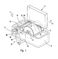
- FIG. 1 and 2 show a gluing unit 1 of an adhesive binder provided for the production of book blocks 2 formed from printed sheets.
- the book blocks 2 transported in the conveying direction F in clamping devices of a conveying device (not visible) are glued to their spine 3 protruding from the clamping device when passing through the gluing unit 1.
- an application roller 4 rotating about a direction transverse to the conveying direction F is provided, which takes up adhesive 5 with the jacket surface immersed in the adhesive 5 occurring in a trough 6 and transfers it overly thick to the back 3 of the book block 2.
- the adhesive film 7 drawn on the application roller 4 passes through an adjustable doctor blade 8, which determines the amount of the adhesive 5 to be transferred to the back 3.
- the distance of the application roller 4 to the back 3 of the book block 2 as well as the distance of the squeegee 8 from the application roller 4 are adjustable or adjustable.
- the back 3 of the book block 2 and the jacket of the application roller 4 have a direction of movement and speed in the same direction in the area of the adhesive transfer.
- the doctor blade 8 scraping off the excess adhesive 5 on the application roller 4 or forming a smooth film surface has a cutting edge-like end edge 9.
- the adhesive 5 stripped off by the squeegee 8 on the application roller 4 flows back into the trough 6.
- a shaft 12 is provided for actuating the squeegee 8, which can be pivoted about an axis 11 running parallel to the axis of rotation 10 of the application roller 4, to which a scraper member 13 is attached.
- the shaft 12 is supported on pivot bearings 14 which are anchored to the tub 6.
- One end of the shaft 12 has a tab-like lever 15 which is connected to a drive rod 16 of a linear motor 17 articulated on a machine frame or the tub 6.
- the drive rod 16 is designed as an extension of the armature 18 (not visible) of the linear motor 17.
- the difference is in Formation of the electric motor 17, the one after an arc section trained anchor 18, the elongated Radial ends of a shaft 12 as an actuator protruding arms 19 forming an obtuse angle are.
Abstract
Description
Die Erfindung betrifft ein Leimwerk zum Auftragen eines Klebstoffes
auf den Rücken oder angrenzende Bereiche eines in einer
Fördereinrichtung vorbeigeführten Buchblocks zusammengetragener
Druckbogen, bestehend aus einer Klebstoff enthaltenden
Wanne, in die wenigstens eine den Klebstoff aufnehmende
und an den Rücken des Buchblocks übertragende, gleichsinnig
mit dem Buchblock angetriebene Auftragswalze eintaucht, welcher
über dem Leimniveau in der Wanne ein durch den veränderbaren
Abstand von der Auftragswalze die auf den Buchblockrücken
zu übertragende Leimfilmdicke bestimmender, zur Verstellung
ein Betätigungsorgan aufweisender Rakel zugeordnet ist.
Für eine qualitativ hochwertige Klebebindung ist die Beleimung
des Rückens eines Buchblocks entscheidend. Das Beleimen mit
zum Buchrücken verstellbaren Auftragswalzen beeinflusst die
Qualität der Beleimung günstig. In vielen Fällen wird der
Klebstoff mit zwei hintereinander angeordneten Walzen übertragen
und dabei mechanisch minimal zwischen die Blattkanten eingetrieben,
sodass eine Einbettung der Blätter in den übertragenen
Klebstoff entsteht.
Die aufzutragende Klebstoffmenge wird durch ein steuerbares
Rakel dosiert, damit sie u.a. nicht in das Buchinnere eindringen
kann. Die Walzenhöheneinstellung und die Rakelstellung
sind dabei sorgfältig aufeinander abzustimmen. Der zuviel aufgetragene
Klebstoff wird abschliessend von einem vertikal verstellbaren
Abstreichrakel oder einer Egalisierwalze ausgeglichen.The invention relates to a gluing unit for applying an adhesive to the spine or adjacent areas of a printed sheet brought together in a conveying device, consisting of a tray containing adhesive, into which at least one adhesive receiving and transferring to the spine of the book block, in the same direction as the book block Driven applicator roller immersed, which above the glue level in the tub is assigned a squeegee film which determines the glue film thickness to be transferred to the book block spine and which has an actuating member for adjustment, due to the variable distance from the applicator roller. For a high-quality perfect binding, the gluing of the back of a book block is crucial. Gluing with application rollers that can be adjusted to the spine has a favorable influence on the quality of the gluing. In many cases, the adhesive is transferred with two rollers arranged one behind the other and is mechanically minimally driven between the sheet edges, so that the sheets are embedded in the transferred adhesive.
The amount of adhesive to be applied is metered by a controllable doctor blade so that it cannot penetrate the inside of the book. The roller height setting and the squeegee position must be carefully coordinated. The excess adhesive applied is then compensated for by a vertically adjustable doctor blade or a leveling roller.
Bei bekannten Leimwerken werden die Rakel manuell oder über
motorisch angetriebene Kurvenscheiben, die auf einen mit der
Rakelwelle verbundenen Steuerhebel einwirken, verstellt bzw.
eingestellt. Es sind auch Vorrichtungen bekannt, bei denen die
Rakel mittels Stellmotoren, die ein Differential- oder Planetengetriebe
ansteuern, verstellbar sind.
Auch von Pneumatikzylindern angetriebene Rakel, denen ein verstellbarer
Anschlag zugeordnet ist, sind bekannt.In known gluing units, the squeegees are adjusted or adjusted manually or via motor-driven cams which act on a control lever connected to the squeegee shaft. Devices are also known in which the doctor blade can be adjusted by means of servomotors which control a differential or planetary gear.
Squeegees driven by pneumatic cylinders, to which an adjustable stop is assigned, are known.
Diese bekannten Vorrichtungen weisen einen relativ hohen Konstruktionsaufwand auf und es sind zu ihrer Wirksamkeit mehrere Elemente beteiligt. Dadurch leidet die Einstellgenauigkeit, insbesondere durch vorhandenes resp. unumgängliches Spiel. Ungenauigkeit ist auch bei pneumatischer Betätigung eines Rakels unvermeidbar, da sich die Geschwindigkeit eines pneumatischen Antriebs nicht proportional zur Maschinengeschwindigkeit verändern lässt.These known devices have a relatively high design effort on and there are several for their effectiveness Elements involved. This affects the setting accuracy, in particular through existing or. essential game. inaccuracy is also with pneumatic actuation of a squeegee unavoidable because the speed of a pneumatic Do not change the drive proportionally to the machine speed leaves.
Deshalb ist es Aufgabe der vorliegenden Erfindung, ein Leimwerk nach der eingangs beschriebenen Art zu schaffen, mit dem auf eine einfache Weise eine genaue und zuverlässige Verstellung eines Rakels erzielt werden kann.Therefore, it is an object of the present invention, a glue unit to create in the manner described above, with the precise and reliable adjustment in a simple way of a doctor blade can be achieved.
Erfindungsgemäss wird diese Aufgabe dadurch gelöst, dass das Betätigungsorgan des Rakels mit dem Antriebsorgan eines steuerbaren Elektromotors antriebsverbunden ist, wodurch gegenüber den bekannten Ausführungen auch weniger Raum beansprucht wird. Vorteilhaft ist das Betätigungsorgan des Rakels als schwenkbare Welle ausgebildet, die auf einfache Art eine direkte Antriebsverbindung mit einem Elektromotor gestattet.According to the invention, this object is achieved in that the Actuator of the squeegee with the drive member of a controllable Electric motor is connected to the drive, whereby opposite the known designs require less space. The actuator of the squeegee is advantageous as pivotable Shaft formed, the direct drive connection in a simple manner allowed with an electric motor.
Zur Betätigung eines Rakels eignet sich in hohem Masse ein als Linearmotor ausgebildeter Elektromotor, da kleine Massen zu beschleunigen sind.To operate a squeegee is highly suitable as Linear motor trained electric motor because of small masses are accelerating.
Selbstverständlich bewährt sich auch ein rotativ arbeitender Elektromotor zur Betätigung eines Rakels.Of course, a rotating one also works well Electric motor for actuating a squeegee.
Anschliessend wird die Erfindung unter Bezugnahme auf die Zeichnung, auf die bezüglich aller in der Beschreibung nicht näher erwähnten Einzelheiten verwiesen wird, anhand zweier Ausführungbeispiele erläutert. In der Zeichnung zeigen:
- Fig. 1
- eine räumliche Darstellung eines Leimwerkes eines Klebebinders und
- Fig. 2
- eine räumliche Darstellung eines alternativen Leimwerks eines Klebebinders.
- Fig. 1
- a spatial representation of a glue unit of a perfect binder and
- Fig. 2
- a spatial representation of an alternative gluing unit of a perfect binder.
Fig. 1 und 2 zeigen ein Leimwerk 1 eines zur Herstellung von
aus Druckbogen gebildeten Buchblocks 2 vorgesehenen Klebebinders.
Die in Einspannvorrichtungen einer Fördereinrichtung
(nicht ersichtlich) in Förderrichtung F transportierten Buchblocks
2 werden beim Passieren des Leimwerks 1 an ihren aus
der Einspannvorrichtung vorstehenden Rücken 3 beleimt. Hierzu
ist eine um eine quer zur Förderrichtung F rotierende Auftragswalze
4 vorgesehen, die mit der in den in einer Wanne 6
vorkommenden Klebstoff 5 eintauchenden Mantelfläche Klebstoff
5 aufnimmt und oberschlächtig an den Rücken 3 des Buchblocks 2
überträgt. Der auf der Auftragswalze 4 aufgezogene Klebstofffilm
7 passiert dabei ein verstellbarer Rakel 8, welcher die
Menge des auf den Rücken 3 zu übertragenden Klebstoffes 5 bestimmt.
Der Abstand der Auftragswalze 4 zum Rücken 3 des Buchblocks
2 wie auch der Abstand des Rakels 8 von der Auftragswalze
4 sind einstellbar bzw. verstellbar. Der Rücken 3 des
Buchblocks 2 und der Mantel der Auftragswalze 4 weisen im Bereich
der Klebstoffübertragung eine gleichsinnige Bewegungsrichtung
und Geschwindigkeit auf.
Der den überschüssigen Klebstoff 5 an der Auftragswalze 4 abstreifende
bzw. eine glatte Filmoberfläche bildende Rakel 8
weist hierzu eine schneidenähnliche Endkante 9 auf. Der vom
Rakel 8 an der Auftragswalze 4 abgestreifte Klebstoff 5
fliesst in die Wanne 6 zurück.
Bei dem in Fig. 1 veranschaulichten Leimwerk 1 ist zur Betätigung
des um eine parallel zur Drehachse 10 der Auftragswalze 4
verlaufende Achse 11 schwenkbaren Rakels 8 eine Welle 12 vorgesehen,
an der ein Abstreiforgan 13 befestigt ist. Die Welle
12 lagert an Schwenklagern 14, die an der Wanne 6 verankert
sind. Das eine Ende der Welle 12 weist einen laschenartigen
Hebel 15 auf, der mit einer Antriebsstange 16 eines an einem
Maschinengestell oder der Wanne 6 angelenkten Linearmotors 17
verbunden ist. Die Antriebsstange 16 ist als Verlängerung des
Ankers 18 (nicht sichtbar) des Linearmotors 17 ausgebildet.1 and 2 show a gluing unit 1 of an adhesive binder provided for the production of
For this purpose, the
In the gluing unit 1 illustrated in FIG. 1, a
Bei dem Leimwerk 1 in Fig. 2 besteht der Unterschied in der
Ausbildung des Elektromotors 17, der einen nach einem Kreisbogenabschnitt
ausgebildeten Anker 18 aufweist, dessen verlängerte
Enden an radial von einer Welle 12 als Betätigungsorgan
abstehenden, einen stumpfen Winkel bildenden Auslegern 19 befestigt
sind.In the gluing unit 1 in Fig. 2, the difference is in
Formation of the
Claims (7)
Priority Applications (4)
| Application Number | Priority Date | Filing Date | Title |
|---|---|---|---|
| DE50014390T DE50014390D1 (en) | 2000-11-17 | 2000-11-17 | Gluing unit for applying an adhesive |
| EP00811089A EP1208998B1 (en) | 2000-11-17 | 2000-11-17 | Device for applying an adhesive |
| JP2001304256A JP2002192041A (en) | 2000-11-17 | 2001-09-28 | Device for applying adhesive |
| US09/987,989 US6565658B2 (en) | 2000-11-17 | 2001-11-16 | Glue spreader |
Applications Claiming Priority (1)
| Application Number | Priority Date | Filing Date | Title |
|---|---|---|---|
| EP00811089A EP1208998B1 (en) | 2000-11-17 | 2000-11-17 | Device for applying an adhesive |
Publications (2)
| Publication Number | Publication Date |
|---|---|
| EP1208998A1 true EP1208998A1 (en) | 2002-05-29 |
| EP1208998B1 EP1208998B1 (en) | 2007-06-06 |
Family
ID=8175034
Family Applications (1)
| Application Number | Title | Priority Date | Filing Date |
|---|---|---|---|
| EP00811089A Expired - Lifetime EP1208998B1 (en) | 2000-11-17 | 2000-11-17 | Device for applying an adhesive |
Country Status (4)
| Country | Link |
|---|---|
| US (1) | US6565658B2 (en) |
| EP (1) | EP1208998B1 (en) |
| JP (1) | JP2002192041A (en) |
| DE (1) | DE50014390D1 (en) |
Cited By (5)
| Publication number | Priority date | Publication date | Assignee | Title |
|---|---|---|---|---|
| DE10242259A1 (en) * | 2002-09-12 | 2004-03-25 | Kolbus Gmbh & Co. Kg | Device for applying adhesive to rear or side of book block in binder, has actuating device with piezoceramic actuator for controlled wiper movement between application and null application positions |
| DE10242260A1 (en) * | 2002-09-12 | 2004-03-25 | Kolbus Gmbh & Co. Kg | Device for applying adhesive to rear or side of book block in binder, has actuating device with piezoceramic actuator for controlled wiper movement between application and null application positions |
| EP1872964A1 (en) | 2006-06-30 | 2008-01-02 | Müller Martini Holding AG | Glueing device for a book block having an adjustable doctor blade |
| CN102529471A (en) * | 2011-12-20 | 2012-07-04 | 中国航空工业集团公司北京航空制造工程研究所 | Method for forming resin film by transfer printing |
| CN104608518A (en) * | 2015-03-03 | 2015-05-13 | 温州锐光机械有限公司 | Sizing system of binding machine |
Families Citing this family (20)
| Publication number | Priority date | Publication date | Assignee | Title |
|---|---|---|---|---|
| US7314075B2 (en) * | 2003-04-04 | 2008-01-01 | Nisca Corporation | Adhesive dispensing apparatus and image forming apparatus |
| ITMI20042546A1 (en) * | 2004-12-29 | 2005-03-29 | Giovanni Gambini | DEVICE FOR DISTRIBUTING GLUE ON AN END OF A LOG ON A LOG OR A SOUL FOR LOG AND RELATED METHOD |
| US8312834B2 (en) * | 2005-04-14 | 2012-11-20 | Hamilton Sundstrand Corporation | Apparatus for applying thin coating |
| EP1937844A1 (en) * | 2005-09-26 | 2008-07-02 | Soreq Nuclear Research Center | Probe for tagging valuables based on dna-metal complex |
| JP2008172917A (en) * | 2007-01-11 | 2008-07-24 | Hiwin Mikrosystem Corp | Tip removal structure for linear motor |
| JP4407719B2 (en) * | 2007-04-26 | 2010-02-03 | コニカミノルタビジネステクノロジーズ株式会社 | Bookbinding equipment |
| US7963733B2 (en) * | 2008-10-01 | 2011-06-21 | Perfect Systems, Llc | Apparatus for and a method of binding of a perfect bound book |
| DE102009031949A1 (en) | 2009-07-07 | 2011-01-13 | Kolbus Gmbh & Co. Kg | Device for applying adhesive to a book block |
| DK2752304T3 (en) | 2011-09-02 | 2016-11-21 | Horizon Int Inc | Gluing unit FOR binding machine |
| JP5913330B2 (en) * | 2011-09-16 | 2016-04-27 | ホリゾン・インターナショナル株式会社 | Gluing unit for the perfect binding device |
| JP6149342B2 (en) * | 2012-03-09 | 2017-06-21 | 大日本印刷株式会社 | Gluing device, bookbinding device |
| JP6065582B2 (en) * | 2012-12-26 | 2017-01-25 | 大日本印刷株式会社 | Perfect binding device, glue applicator, doctor blade |
| US8920096B2 (en) | 2012-12-27 | 2014-12-30 | Donnie Donselman | Book binding adhesive application controller |
| JP2016043488A (en) * | 2014-08-19 | 2016-04-04 | 株式会社Isowa | Pasting device |
| CN106515250B (en) * | 2017-01-08 | 2017-11-03 | 周茂春 | A kind of counterfoil attachment means of accounting finance |
| US10864567B2 (en) * | 2018-04-17 | 2020-12-15 | Government Of The United States As Represented By The Secretary Of The Army | Systems and methods for electroprocessing a gun barrel using a moving electrode |
| CN111204146B (en) * | 2020-01-07 | 2021-10-15 | 西安天成印务有限公司 | Thin volume rubber coating device |
| CN112776500B (en) * | 2020-12-30 | 2023-11-14 | 深圳精密达智能机器有限公司 | Cam glue breaking device based on planetary gear train |
| CN113414053B (en) * | 2021-07-13 | 2022-04-15 | 深圳市精联精密科技有限公司 | Profiling circumference gluing mechanism and gluing method thereof |
| CN113953134B (en) * | 2021-10-22 | 2022-11-25 | 漳州市天辰纸品包装有限公司 | Gluing device for paper product packaging box |
Citations (3)
| Publication number | Priority date | Publication date | Assignee | Title |
|---|---|---|---|---|
| US5693142A (en) * | 1993-03-26 | 1997-12-02 | Nordson Corporation | Wheel applicator device for applying adhesive, especially to the spines of books during bookbinding |
| EP0839584A2 (en) * | 1996-11-01 | 1998-05-06 | Marquip, Inc. | Improved apparatus and method for applying a viscous liquid to a material surface |
| DE19722456A1 (en) * | 1997-05-28 | 1998-12-03 | Voith Sulzer Papiermasch Gmbh | Web coating apparatus e.g. for application of liquid or paste |
Family Cites Families (5)
| Publication number | Priority date | Publication date | Assignee | Title |
|---|---|---|---|---|
| US4014287A (en) * | 1975-08-04 | 1977-03-29 | Comstock & Wescott, Inc. | High speed fluid applicator |
| DD144383A1 (en) * | 1979-08-13 | 1980-10-15 | Gerald Winker | DEVICE FOR APPLYING MELT ADHESIVE TO BLOCKS |
| JPS6225254Y2 (en) * | 1981-06-03 | 1987-06-27 | ||
| CH662310A5 (en) * | 1983-11-22 | 1987-09-30 | Grapha Holding Ag | BOOKBINDING MACHINE. |
| JP3805490B2 (en) * | 1997-06-20 | 2006-08-02 | ホリゾン・インターナショナル株式会社 | Gluing device for paper binding |
-
2000
- 2000-11-17 DE DE50014390T patent/DE50014390D1/en not_active Expired - Lifetime
- 2000-11-17 EP EP00811089A patent/EP1208998B1/en not_active Expired - Lifetime
-
2001
- 2001-09-28 JP JP2001304256A patent/JP2002192041A/en active Pending
- 2001-11-16 US US09/987,989 patent/US6565658B2/en not_active Expired - Lifetime
Patent Citations (3)
| Publication number | Priority date | Publication date | Assignee | Title |
|---|---|---|---|---|
| US5693142A (en) * | 1993-03-26 | 1997-12-02 | Nordson Corporation | Wheel applicator device for applying adhesive, especially to the spines of books during bookbinding |
| EP0839584A2 (en) * | 1996-11-01 | 1998-05-06 | Marquip, Inc. | Improved apparatus and method for applying a viscous liquid to a material surface |
| DE19722456A1 (en) * | 1997-05-28 | 1998-12-03 | Voith Sulzer Papiermasch Gmbh | Web coating apparatus e.g. for application of liquid or paste |
Cited By (9)
| Publication number | Priority date | Publication date | Assignee | Title |
|---|---|---|---|---|
| DE10242259A1 (en) * | 2002-09-12 | 2004-03-25 | Kolbus Gmbh & Co. Kg | Device for applying adhesive to rear or side of book block in binder, has actuating device with piezoceramic actuator for controlled wiper movement between application and null application positions |
| DE10242260A1 (en) * | 2002-09-12 | 2004-03-25 | Kolbus Gmbh & Co. Kg | Device for applying adhesive to rear or side of book block in binder, has actuating device with piezoceramic actuator for controlled wiper movement between application and null application positions |
| US6908513B2 (en) | 2002-09-12 | 2005-06-21 | Kolbus Gmbh & Co. Kg | Device for applying an adhesive to the spine of an inner book or to areas of the lateral faces adjacent thereto |
| DE10242259B4 (en) * | 2002-09-12 | 2009-11-26 | Kolbus Gmbh & Co. Kg | Device for applying an adhesive to the back or near region of the side surfaces of a book block |
| EP1872964A1 (en) | 2006-06-30 | 2008-01-02 | Müller Martini Holding AG | Glueing device for a book block having an adjustable doctor blade |
| US7959394B2 (en) | 2006-06-30 | 2011-06-14 | Müller Martini Holding AG | Glue applicator for applying an adhesive to the spine or adjacent areas of a book block being conducted past the glue applicator in a transport direction |
| CN102529471A (en) * | 2011-12-20 | 2012-07-04 | 中国航空工业集团公司北京航空制造工程研究所 | Method for forming resin film by transfer printing |
| CN104608518A (en) * | 2015-03-03 | 2015-05-13 | 温州锐光机械有限公司 | Sizing system of binding machine |
| CN104608518B (en) * | 2015-03-03 | 2016-04-20 | 温州锐光机械有限公司 | A kind of glue spreading system of notebook packager |
Also Published As
| Publication number | Publication date |
|---|---|
| EP1208998B1 (en) | 2007-06-06 |
| US6565658B2 (en) | 2003-05-20 |
| DE50014390D1 (en) | 2007-07-19 |
| US20020061241A1 (en) | 2002-05-23 |
| JP2002192041A (en) | 2002-07-10 |
Similar Documents
| Publication | Publication Date | Title |
|---|---|---|
| EP1208998A1 (en) | Device for applying an adhesive | |
| EP1872964B1 (en) | Glueing device for a book block having an adjustable doctor blade | |
| EP1780038B2 (en) | Device for grinding a book cover onto the glued back of a book block having a separate drive | |
| DE3149335A1 (en) | "MACHINE FOR LAYING ASPHALT" | |
| CH644535A5 (en) | SELECTIVELY CONVERTABLE DEVICE FOR COATING A MOVING MATERIAL RAIL. | |
| EP0021070B1 (en) | Device and process for applying adhesive, particularly for glueing piles of sheets | |
| EP1084864B1 (en) | Gluing device for the application of an adhesive on to the back or bordering areas of a conveyed book block | |
| DE2939102C2 (en) | ||
| EP1780037A1 (en) | Apparatus for gluing the backs of book blocks | |
| DE2359413C3 (en) | Device for coating running material webs made of paper, cardboard, plastic or the like. | |
| EP1728646A1 (en) | Method, apparatus and machine for applying flowable gue | |
| DE69824709T2 (en) | Method and device for bonding two plate-shaped objects | |
| DE2107163C3 (en) | Device for the simultaneous application of several parallel, thin strip coatings on the surface of an electrically insulating carrier | |
| DE3700091C1 (en) | Dough-plaiting apparatus | |
| DE2815143A1 (en) | Binding device for automatic book binding machines - includes binding cover guide table below book block conveyor and speed change for cover supply unit | |
| CH626833A5 (en) | ||
| CH668944A5 (en) | GLUING UNIT FOR THE MANUFACTURE OF BOOK BLOCKS AND MULTI-PLY BOOKLETS WITH LIMITED GLUING. | |
| EP1072435B1 (en) | Device for applying glue to the backs of book blocks in a casing-in machine | |
| EP0120482B1 (en) | Device for applying a layer of fine ceramic material to a carrier | |
| DE7147739U (en) | DEVICE FOR APPLYING A LIQUID MEDIUM FOR THE FORMATION OF A COATING LAYER ON PANEL-SHAPED OBJECTS PREFERRED FROM WOOD | |
| DE202008006314U1 (en) | Apparatus for applying adhesive | |
| CH672443A5 (en) | Squeegee control for glue units. | |
| DE102005046684A1 (en) | Adhesive application apparatus, especially useful in book production, having adhesive tank located in container under protective atmosphere to stabilize adhesive and minimize need for cleaning | |
| DE2259140C3 (en) | Glue application device | |
| DE102009009295A1 (en) | Apparatus for applying adhesive |
Legal Events
| Date | Code | Title | Description |
|---|---|---|---|
| PUAI | Public reference made under article 153(3) epc to a published international application that has entered the european phase |
Free format text: ORIGINAL CODE: 0009012 |
|
| AK | Designated contracting states |
Kind code of ref document: A1 Designated state(s): AT BE CH CY DE DK ES FI FR GB GR IE IT LI LU MC NL PT SE TR |
|
| AX | Request for extension of the european patent |
Free format text: AL;LT;LV;MK;RO;SI |
|
| 17P | Request for examination filed |
Effective date: 20020829 |
|
| AKX | Designation fees paid |
Designated state(s): CH DE FR GB IT LI |
|
| 17Q | First examination report despatched |
Effective date: 20041207 |
|
| GRAP | Despatch of communication of intention to grant a patent |
Free format text: ORIGINAL CODE: EPIDOSNIGR1 |
|
| GRAS | Grant fee paid |
Free format text: ORIGINAL CODE: EPIDOSNIGR3 |
|
| GRAA | (expected) grant |
Free format text: ORIGINAL CODE: 0009210 |
|
| AK | Designated contracting states |
Kind code of ref document: B1 Designated state(s): CH DE FR GB IT LI |
|
| REG | Reference to a national code |
Ref country code: GB Ref legal event code: FG4D Free format text: NOT ENGLISH |
|
| REG | Reference to a national code |
Ref country code: CH Ref legal event code: EP |
|
| REF | Corresponds to: |
Ref document number: 50014390 Country of ref document: DE Date of ref document: 20070719 Kind code of ref document: P |
|
| GBT | Gb: translation of ep patent filed (gb section 77(6)(a)/1977) |
Effective date: 20070725 |
|
| ET | Fr: translation filed | ||
| PLBE | No opposition filed within time limit |
Free format text: ORIGINAL CODE: 0009261 |
|
| STAA | Information on the status of an ep patent application or granted ep patent |
Free format text: STATUS: NO OPPOSITION FILED WITHIN TIME LIMIT |
|
| 26N | No opposition filed |
Effective date: 20080307 |
|
| REG | Reference to a national code |
Ref country code: FR Ref legal event code: PLFP Year of fee payment: 16 |
|
| PGFP | Annual fee paid to national office [announced via postgrant information from national office to epo] |
Ref country code: GB Payment date: 20151123 Year of fee payment: 16 |
|
| PGFP | Annual fee paid to national office [announced via postgrant information from national office to epo] |
Ref country code: FR Payment date: 20151123 Year of fee payment: 16 |
|
| PGFP | Annual fee paid to national office [announced via postgrant information from national office to epo] |
Ref country code: CH Payment date: 20160222 Year of fee payment: 16 Ref country code: IT Payment date: 20151130 Year of fee payment: 16 |
|
| PGFP | Annual fee paid to national office [announced via postgrant information from national office to epo] |
Ref country code: DE Payment date: 20161116 Year of fee payment: 17 |
|
| REG | Reference to a national code |
Ref country code: CH Ref legal event code: PL |
|
| GBPC | Gb: european patent ceased through non-payment of renewal fee |
Effective date: 20161117 |
|
| PG25 | Lapsed in a contracting state [announced via postgrant information from national office to epo] |
Ref country code: CH Free format text: LAPSE BECAUSE OF NON-PAYMENT OF DUE FEES Effective date: 20161130 Ref country code: LI Free format text: LAPSE BECAUSE OF NON-PAYMENT OF DUE FEES Effective date: 20161130 |
|
| REG | Reference to a national code |
Ref country code: FR Ref legal event code: ST Effective date: 20170731 |
|
| PG25 | Lapsed in a contracting state [announced via postgrant information from national office to epo] |
Ref country code: IT Free format text: LAPSE BECAUSE OF NON-PAYMENT OF DUE FEES Effective date: 20161117 Ref country code: FR Free format text: LAPSE BECAUSE OF NON-PAYMENT OF DUE FEES Effective date: 20161130 |
|
| PG25 | Lapsed in a contracting state [announced via postgrant information from national office to epo] |
Ref country code: GB Free format text: LAPSE BECAUSE OF NON-PAYMENT OF DUE FEES Effective date: 20161117 |
|
| REG | Reference to a national code |
Ref country code: DE Ref legal event code: R119 Ref document number: 50014390 Country of ref document: DE |
|
| PG25 | Lapsed in a contracting state [announced via postgrant information from national office to epo] |
Ref country code: DE Free format text: LAPSE BECAUSE OF NON-PAYMENT OF DUE FEES Effective date: 20180602 |