EP1208991A2 - Inkjet colour printing method and printer - Google Patents
Inkjet colour printing method and printer Download PDFInfo
- Publication number
- EP1208991A2 EP1208991A2 EP01204321A EP01204321A EP1208991A2 EP 1208991 A2 EP1208991 A2 EP 1208991A2 EP 01204321 A EP01204321 A EP 01204321A EP 01204321 A EP01204321 A EP 01204321A EP 1208991 A2 EP1208991 A2 EP 1208991A2
- Authority
- EP
- European Patent Office
- Prior art keywords
- scanning direction
- colour
- colours
- nozzles
- arrays
- Prior art date
- Legal status (The legal status is an assumption and is not a legal conclusion. Google has not performed a legal analysis and makes no representation as to the accuracy of the status listed.)
- Granted
Links
Images



Classifications
-
- B—PERFORMING OPERATIONS; TRANSPORTING
- B41—PRINTING; LINING MACHINES; TYPEWRITERS; STAMPS
- B41J—TYPEWRITERS; SELECTIVE PRINTING MECHANISMS, i.e. MECHANISMS PRINTING OTHERWISE THAN FROM A FORME; CORRECTION OF TYPOGRAPHICAL ERRORS
- B41J2/00—Typewriters or selective printing mechanisms characterised by the printing or marking process for which they are designed
- B41J2/005—Typewriters or selective printing mechanisms characterised by the printing or marking process for which they are designed characterised by bringing liquid or particles selectively into contact with a printing material
- B41J2/01—Ink jet
- B41J2/135—Nozzles
- B41J2/145—Arrangement thereof
- B41J2/15—Arrangement thereof for serial printing
-
- B—PERFORMING OPERATIONS; TRANSPORTING
- B41—PRINTING; LINING MACHINES; TYPEWRITERS; STAMPS
- B41J—TYPEWRITERS; SELECTIVE PRINTING MECHANISMS, i.e. MECHANISMS PRINTING OTHERWISE THAN FROM A FORME; CORRECTION OF TYPOGRAPHICAL ERRORS
- B41J19/00—Character- or line-spacing mechanisms
- B41J19/14—Character- or line-spacing mechanisms with means for effecting line or character spacing in either direction
- B41J19/142—Character- or line-spacing mechanisms with means for effecting line or character spacing in either direction with a reciprocating print head printing in both directions across the paper width
- B41J19/147—Colour shift prevention
-
- B—PERFORMING OPERATIONS; TRANSPORTING
- B41—PRINTING; LINING MACHINES; TYPEWRITERS; STAMPS
- B41J—TYPEWRITERS; SELECTIVE PRINTING MECHANISMS, i.e. MECHANISMS PRINTING OTHERWISE THAN FROM A FORME; CORRECTION OF TYPOGRAPHICAL ERRORS
- B41J2/00—Typewriters or selective printing mechanisms characterised by the printing or marking process for which they are designed
- B41J2/005—Typewriters or selective printing mechanisms characterised by the printing or marking process for which they are designed characterised by bringing liquid or particles selectively into contact with a printing material
- B41J2/01—Ink jet
- B41J2/21—Ink jet for multi-colour printing
- B41J2/2132—Print quality control characterised by dot disposition, e.g. for reducing white stripes or banding
-
- B—PERFORMING OPERATIONS; TRANSPORTING
- B41—PRINTING; LINING MACHINES; TYPEWRITERS; STAMPS
- B41J—TYPEWRITERS; SELECTIVE PRINTING MECHANISMS, i.e. MECHANISMS PRINTING OTHERWISE THAN FROM A FORME; CORRECTION OF TYPOGRAPHICAL ERRORS
- B41J2/00—Typewriters or selective printing mechanisms characterised by the printing or marking process for which they are designed
- B41J2/485—Typewriters or selective printing mechanisms characterised by the printing or marking process for which they are designed characterised by the process of building-up characters or image elements applicable to two or more kinds of printing or marking processes
- B41J2/505—Typewriters or selective printing mechanisms characterised by the printing or marking process for which they are designed characterised by the process of building-up characters or image elements applicable to two or more kinds of printing or marking processes from an assembly of identical printing elements
- B41J2/51—Typewriters or selective printing mechanisms characterised by the printing or marking process for which they are designed characterised by the process of building-up characters or image elements applicable to two or more kinds of printing or marking processes from an assembly of identical printing elements serial printer type
-
- B—PERFORMING OPERATIONS; TRANSPORTING
- B41—PRINTING; LINING MACHINES; TYPEWRITERS; STAMPS
- B41J—TYPEWRITERS; SELECTIVE PRINTING MECHANISMS, i.e. MECHANISMS PRINTING OTHERWISE THAN FROM A FORME; CORRECTION OF TYPOGRAPHICAL ERRORS
- B41J2/00—Typewriters or selective printing mechanisms characterised by the printing or marking process for which they are designed
- B41J2/005—Typewriters or selective printing mechanisms characterised by the printing or marking process for which they are designed characterised by bringing liquid or particles selectively into contact with a printing material
- B41J2/01—Ink jet
- B41J2/135—Nozzles
- B41J2/14—Structure thereof only for on-demand ink jet heads
- B41J2002/14475—Structure thereof only for on-demand ink jet heads characterised by nozzle shapes or number of orifices per chamber
Definitions
- the invention relates to a method of colour printing with an ink jet printer having a printhead which is reciprocatingly moved in forward and return scan passes in a main scanning direction, in which an even number of nozzle arrays is provided for each of at least two colours, and said nozzle arrays are symmetrically arranged in the main scanning direction.
- the invention further relates to an ink jet printer for carrying out this method.
- the printhead of an ink jet colour printer typically has at least one nozzle array for each colour.
- three nozzle arrays will be provided for the colours cyan (C), magenta (M) and yellow (Y).
- Each nozzle array comprises a plurality of nozzles which, in case of a linear array, for example, are arranged equidistantly on a line that extends in a direction orthogonal to the main scanning direction. Then, the distance between neighbouring nozzles corresponds to the distance between adjacent pixels of the image to be printed, so that the number of pixel lines that can be printed in one scan pass corresponds to the number of nozzles in the array.
- the nozzle arrays for the various colours are sequentially arranged in the main scanning direction, for example in the order C-M-Y.
- the corresponding nozzles of the various arrays are energized at appropriate timings, so that ink droplets jetted out from the various nozzles impinge on the recording sheet essentially at the same location, i.e. the location of the pixel to be printed.
- the ink droplets of different colours composing the pixel will be superposed one upon the other or will at least overlap with each other.
- the ink droplets of different colours will be superposed on the recording sheet in the order C-M-Y, and during a return stroke or scan pass of the printhead, the ink droplets will be superposed in reverse order.
- US-A-4 528 576 discloses a printing method according to the preamble of claim 1 in which two nozzle arrays are provided for each colour, and the nozzle arrays are symmetrically arranged in the main scanning direction, for example in the nested sequence C-M-Y-Y-M-C.
- the nozzle head moves in forward direction, only the first three nozzle arrays are used, so that the colours are superposed in the order C-M-Y.
- the other three nozzles heads are used, so that the colours are again superposed in the same order.
- this object is achieved by a method as described in the preamble of claim 1, in which, for printing a single pixel composed of at least two colours with high density, ink dots of each of these colours are formed in even numbers by activating the corresponding nozzles of the symmetrically arranged arrays at appropriate timings in the same scan pass of the printhead.
- the pixel will be composed of at least four ink droplets two of which are formed by yellow ink and the other two of which are formed by cyan ink.
- the order in which these ink droplets are printed and superposed will for example be C-Y-Y-C, irrespective of the direction of the scan pass.
- This method has the advantage that it permits a high printing resolution without degrading the image density of the printed image.
- the size of the pixels to be printed, and hence the printing resolution is determined by the pitch of the nozzles in the array.
- Each nozzle is connected to an ink channel or cavity in which the ink liquid is pressurized by means of a piezoelectric actuator or the like.
- the space available for the various cavities is limited by the pitch of nozzles.
- the cross section of the nozzle orifice must be smaller than the cross section of the cavity in order to achieve a nozzle action which is necessary for forming the ink droplets.
- the maximum diameter of the nozzle orifice is roughly proportional to the pitch of the nozzles. If the printing resolution is to be increased by a certain factor r, then, roughly speaking, the whole nozzle array should be scaled down by the factor 1/r.
- the diameter of the ink droplet expelled from the nozzle is roughly proportional to the diameter of the nozzle orifice, so that the volume of the ink droplets will be decreased by a factor 1/r3.
- the surface area of the pixels to be printed will be decreased only by the factor 1/r2, so that the image density, i.e. the ink volume per unit surface area will decrease approximately with 1/r.
- the invention combines this principle for improving the image density with the known method of eliminating shifts of the hue in colour printing and thereby makes more efficient use of the nozzle arrays which must be provided at least two-fold for each colour, anyway.
- the printhead comprises two nozzle arrays for each colour, and the nozzle arrays are arranged in two blocks, so that each block comprises a complete set of nozzle arrays for each colour, and one block is the mirror image of the other.
- the nozzle blocks themselves are mirror-symmetric with respect to a median plane which intersects the linear nozzle arrays at right angles.
- the two nozzle blocks may have an identical construction and may be manufactured in exactly the same procedure, and when the blocks are mounted to the printhead, one of them is mounted in an orientation rotated by 180°.
- This increases not only the production efficiency but has the further advantage that the effect of certain defects of the nozzle arrays may be mitigated.
- Such defects may for example consist of a slight misalignment of the nozzles within the nozzle arrays or of minor defects of the nozzle orifices which cause the ink droplets to be jetted out not exactly along the axis of the nozzle but under a slight scew angle.
- the individual pixels will be formed by exactly superposing the colour dots one upon the other.
- the printing resolution will be unisotropic, which may be beneficial in certain applications as a compromise between highest possible printing speed and reproduction of sufficient details of the printed image.
- the offset between the dots may be either in the main scanning direction or in sub-scanning direction. In both cases, the offset can be brought about by a corresponding physical offset of the two nozzle blocks. If the offset is in the main scanning direction, it may alternatively be brought about by a corresponding shift between the timings at which the nozzles of the two blocks are energized.
- an ink jet colour printer comprises a platen 10 on which a recording sheet 12 is advanced in a sub-scanning direction Y.
- a printhead 14 is moved back and forth along the platen 10 in a main scanning direction X and comprises a carriage 16 mounted on guide bares 18, 20 and carrys a number of nozzle arrays C1, M1, Y1, Y2, M2 and C2 which are arranged in that order in the main-scanning direction X.
- Each nozzle array comprises a number N of nozzles 22 which, in the example shown, are arranged on a single straight line extending in the sub-scanning direction Y.
- the vertical distance of neighbouring nozzles corresponds to the height of the pixels to be printed on the recording sheet 12.
- These pixels are printed by ejecting droplets of coloured ink from the nozzles 22 in a direction Z normal to the plane of the recording sheet 12 where it faces the printhead.
- the droplets may be generated by means of thermal actuators (bubble-jet) or by means of piezoelectric actuators, for example.
- the printhead 14 makes a forward scan pass in the +X-direction, a number N of image lines is printed simultaneously on the recording sheet 12. Then, the recording sheet 12 is advanced by a distance corresponding to the height of the nozzle arrays, and another N lines are printed during the return scan pass of the printhead 14.
- the nozzle arrays are arranged in two blocks 24, 26, and each of these blocks comprises three nozzle arrays, one for each of the basic colours cyan, magenta and yellow.
- the reference signs for the nozzle arrays indicate the colour of the ink: C1 and C2 stand for the colour "cyan”, M1 and M2 stand for the colour "magenta” and Y1 and Y2 stand for the colour "yellow”.
- the two blocks 24 and 26 have an identical construction and are mirror-symmetric with respect to a median plane E which is parallel to the X-Z plane. Compared to the block 24, the block 26 is mounted on the carriage 16 "top down” so that the order of colours in the block 26 is the mirror image of the order of colours in the block 24.
- the printhead 14 is connected to a control unit 28 which controls the actuators for the various nozzles 22 in accordance with the image information of the image to be printed.
- FIG. 1 a part of the recording sheet 12 is shown in cross-section, and the position of a pixel P to be printed is indicated by a rectangle within the cross-section of the recording sheet 12.
- the printhead 14 makes a forward scan pass in the +X-direction. It is assumed that the colour of the pixel P to be printed shall be green, i.e. the pixel is to be composed of cyan and yellow colour components.
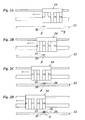
- Figure 2A illustrates the situation in which the first cyan nozzle array C1 of the printhead has reached the position of the pixel P, and a first cyan dot 30 has been formed on the recording sheet.
- the first yellow nozzle array Y1 has reached the position of the pixel P, and a first yellow dot 32 has been formed on top of the dot 30, so that the colour of the pixel P becomes the mixed colour "green".
- the colour density of the dots 30, 32 is not sufficient for giving a saturated green pixel, so that the resulting printed image would look faint.
- the second yellow nozzle array Y2 has reached the position of the pixel P and a second yellow dot 34 is superposed on the dot 32.
- another cyan dot 36 is superposed on top of the dot 34, so that a pixel P with the mixed colour "green" and with a satisfactorily high image density is obtained.
- the pixel P has a symmetric layer structure with the bottom layer and the top layer being formed by cyan ink and the two innermost layers being formed by yellow ink. It will be understood that the thickness of the layers as well as the thickness of the recording sheet 12 are grossly exaggerated in the drawing. In practice, the ink layers formed successively by the nozzle arrays C1, Y1, Y2 and C2 will not be strictly separated from one another, because the ink will not have completely dried-out when it is deposited on the recording sheet 12. However, since the mixing of the ink is not complete, the hue or colour impression visible to the human eye is influenced by the order of the ink layers forming the pixel P.
- the symmetric order of the ink layers shown in figure 2D has the advantage that a good balance between the colour components cyan and yellow is achieved.
- the main advantage results from the fact that exactly the same order of ink layers is obtained when a green pixel P is printed in the return scan pass of the printhead 14. Then, the only difference would be that the nozzle arrays are energized in reverse order, i.e. C2-Y2-Y1-C1, but the order of colours would be same.
- the hue or colour impression of this area will be uniform even if the height of the area is larger than the height of the nozzle arrays, and, accordingly, the area is composed of stripes printed alternatingly in forward and return scan passes.
- the printhead 10 may comprise additional nozzle arrays for black ink, which have not been shown here for simplicity.
- the invention is not limited to the case that a pixel P is formed by two dots of the same colour. If the printing resolution is increased further and, accordingly, the volume of the ink droplets is decreased further, it may be possible to employ a printhead with four nozzle arrays for each colour. Again, these arrays would be arranged such that the sequence of colours is mirror-symmetric.
- each pixel P has essentially the same dimensions in the main scanning direction X and the sub-scanning direction Y, so that the printed image would consist of a pattern of square pixels.
- Figures 3A-D and figures 4A-D illustrate a modified embodiment, in which a pattern of elongated rectangular pixels is used, as is shown in figure 5.
- the pixels P are elongated in the main scanning direction X, so that the printing resolution in the sub-scanning direction Y would be higher than in the main scanning direction.
- the ink dots 34, 36 formed by individual ink droplets have an essentially circular shape, and the elongated shape of the pixel P is obtained by a slight offset of the dots 34, 36.
- the dots superposed one on the other are not exactly congruent, although at there is still a significant overlap between these dots.
- Figures 3A-D and 4A-D illustrate the locations of four subsequent pixels P1, P2, P3 and P4 in the main scanning direction X, and it is assumed that a green line is to be printed which has width in the X-direction of three pixel, but which is centered on the boarder line between the pixels P2 and P3. It may further be assumed that the ink dots printed with the nozzles of the block 24 are slightly offset from the center positions of the pixels in the -X-direction (to the right in figure 3), whereas the ink dots printed with the block 26 are offset in +X-direction. These offsets may be obtained either by the physical arrangement of the blocks 24, 26 on the carriage 16 or by a suitable time delay between the timings at which the nozzles of the two blocks are energized.
- the printhead 14 moves in the +X-direction (to the left) in a forward scan pass.
- the first cyan nozzle array C1 has passed over the pixels P1-P4 and has printed cyan dots 30 in each of the pixels P2, P3 and P4.
- the first yellow nozzle array Y1 has passed over the pixels and has printed yellow dots 32 right on top of each of the dots 30.
- the nozzles of the block 24 are not energized for the pixel P1.
- the second yellow nozzle array Y2 has passed over the pixels and has been energized for printing the second yellow dot 34 in the pixels P1-P3 but not in the pixel P4. It will be observed that the dots 34 are shifted to the left end of the respective pixels.
- the second cyan nozzle array C2 has passed over the pixels and has printed the top-layer cyan dots 36 in each of the pixels P1-P3.
- the pixels P2 and P3 are formed by four partly overlapping colour layers with symmetric colour sequence.
- the pixels P1 and P4 are each formed by only two dots or colour layers with mutually opposite colour sequence, and these dots are placed directly adjacent to the pixels P2 and P3, repectively.
- the optical density of the pixels P1 and P4 is smaller than that of the pixels P2 and P3, and the overall impression will be that of a green line having a width of approximately 3 pixel.
- the offset of the dots formed by the nozzle blocks 24 and 26 is used to improve the printing resolution in the main scanning direction X.
- Figures 4A-D illustrate the printing procedure for another section of the green line, which is printed during a return scan pass of the printhead. It can be seen that the arrangement of dots and the layer structure of the pixels in figures 4A-D is just the mirror image of what is shown in figures 3A-D.
- the resulting hue or colour impression will be the same in in the forward and return scan passes, i.e. the hue is independent of the direction of the scan pass.
- a shift in hue occurs only for the pixels P1 and P4 which form the edge of the green line. However, since these shifts in hue are limited to less than one pixel in the direction normal to the edge, they are not perceptible to the human eye, and the formation of visible artefacts due to the opposite scan pass directions is prevented as in the first embodiment.
- Figures 6A-D illustrate an embodiment in which the pixels P, Q are elongated in the sub-scanning direction Y. This may be achieved for example by an appropriate offset of the blocks 24, 26 in the sub-scanning direction.
- Figures 6A-D illustrate the process of printing a two-pixel wide green line which extends in the main scanning direction.
- the recording sheet 12 is advanced, so that the pixels Q of the next line can be printed with the uppermost nozzles 22 in the return scan pass.
- the first cyan and yellow dots 30, 32 have been printed with the nozzle arrays C2, Y2 of the block 26 moving in -X-direction.
- the second yellow and cyan dots 34, 36 for the pixel Q are printed with the block 24.
- the pixels Q and P in figure 6D have the same sequence of colour layers and are mirror images of each other only in respect to the offset of the dots. This offset, however, does not have a noticeable influence of the colour impression, so that no change in hue will be observed and the boarder between the image lines printed in the forward and return scan passes.
Landscapes
- Engineering & Computer Science (AREA)
- Quality & Reliability (AREA)
- Ink Jet (AREA)
Abstract
Description
- Fig. 1
- is a schematic perspective view of an ink jet colour printer according to the invention;
- Fig. 2A-D
- are schematic top plan views of the printer shown in figure 1, illustrating the formation of a colour pixel during one scan pass of the printhead;
- Figs. 3A-D
- are schematic cross-sectional views of a recording sheet, illustrating a formation of pixels, that are elongated in the main scanning direction, during a forward scan pass of the printhead;
- Figs. 4A-D
- are cross-sectional views corresponding to figures 3A-D and showing the formation of pixels during a return scan pass;
- Fig. 5 is a
- pixel pattern illustrating the shape of partially overlapping colour dots forming a pixel; and
- Figs. 6A-D
- show longitudinal sections of the recording sheet and illustrate the formation of pixels that are elongated in the sub-scanning direction.
Claims (7)
- Method of colour printing with an ink jet printer having a printhead (10) which is reciprocatingly moved in forward and return scan passes in a main scanning direction (X), in which an even number of nozzle arrays (C1, M1, Y1; Y2, M2, C2) is provided for each of at least two colours, and said nozzles arrays are symmetrically arranged in the main scanning direction (X), characterized in that, for printing a single pixel (P; P2; P3; Q) composed of at least two colours with high density, ink dots (30, 32, 34, 36) of each of these colours are formed in even numbers by activating the corresponding nozzles (22) of the symmetrically arranged arrays at appropriate timings in the same scan pass of the printhead (14).
- Method according to claim 1, wherein ink dots (30, 36; 32, 34) of the same colour and composing the same pixel (P2, P3) are formed with substantial overlap but slightly offset in the main scanning direction (X).
- Method according to claim 1, wherein ink dots (30, 36; 32, 34) of the same colour and composing the same pixel (P, Q) are formed with substantial overlap but slightly offset in the sub-scanning direction (Y).
- Ink jet colour printer comprising:characterized in that the control unit (28) is arranged for activating the nozzles (22) of the symmetrically arranged arrays at appropriate timings such that, for printing a single pixel (P; P2, P3; Q) composed of at least two colours with high density, ink dots (30, 32, 34, 36) of each of these colours are formed in even numbers in the same scan pass of the printhead (14).a printhead (14) which is reciprocatingly moved in forward and return scan passes in a main scanning direction (X), in which an even number of nozzles arrays (C1, M1, Y1; Y2, M2, C2) is provided for each of at least two colours, and said nozzle arrays are symmetrically arranged in the main scanning direction, anda control unit (28) energizing the nozzles (22) of the nozzle arrays in accordance with the image information to be printed,
- Printer according to claim 4, wherein the nozzle arrays (C1, M1, Y1; Y2, M2, C2) are arranged in the main scanning direction (X) in an even number of blocks (24, 26) which each include one nozzle array of each colour.
- Printer according to claim 5, wherein the blocks (24, 26) have an identical construction and are mirror-symmetric with respect to the median plane (E) extending in parallel with the main scanning direction (X) and normal to the sub-scanning direction (Y), and one half of the total number of blocks (24, 26) is mounted to the printhead (14) in reserve orientation relative to the other half of the blocks.
- Printer according to any of the claims 4 to 6, wherein the nozzle arrays (C1, C2; M1, M2; Y1, Y2) of the same colour are arranged such that their nozzles (22) are offset from one another in the sub-scanning direction (Y) by an amount smaller than the dimension of the pixel (P, Q) in that direction.
Priority Applications (1)
| Application Number | Priority Date | Filing Date | Title |
|---|---|---|---|
| EP01204321A EP1208991B1 (en) | 2000-11-23 | 2001-11-09 | Inkjet colour printing method and printer |
Applications Claiming Priority (3)
| Application Number | Priority Date | Filing Date | Title |
|---|---|---|---|
| EP00204159 | 2000-11-23 | ||
| EP00204159 | 2000-11-23 | ||
| EP01204321A EP1208991B1 (en) | 2000-11-23 | 2001-11-09 | Inkjet colour printing method and printer |
Publications (3)
| Publication Number | Publication Date |
|---|---|
| EP1208991A2 true EP1208991A2 (en) | 2002-05-29 |
| EP1208991A3 EP1208991A3 (en) | 2002-07-24 |
| EP1208991B1 EP1208991B1 (en) | 2006-05-03 |
Family
ID=26072866
Family Applications (1)
| Application Number | Title | Priority Date | Filing Date |
|---|---|---|---|
| EP01204321A Expired - Lifetime EP1208991B1 (en) | 2000-11-23 | 2001-11-09 | Inkjet colour printing method and printer |
Country Status (1)
| Country | Link |
|---|---|
| EP (1) | EP1208991B1 (en) |
Cited By (2)
| Publication number | Priority date | Publication date | Assignee | Title |
|---|---|---|---|---|
| US8083338B2 (en) | 2004-05-06 | 2011-12-27 | Agfa Graphics N.V. | Radiation-curable ink-jet printing |
| EP3330092A1 (en) * | 2016-11-30 | 2018-06-06 | Canon Kabushiki Kaisha | Printing apparatus and printing method |
Family Cites Families (4)
| Publication number | Priority date | Publication date | Assignee | Title |
|---|---|---|---|---|
| US4528576A (en) * | 1982-04-15 | 1985-07-09 | Canon Kabushiki Kaisha | Recording apparatus |
| JPS58215351A (en) * | 1982-06-08 | 1983-12-14 | Canon Inc | Image recorder |
| EP0955174A3 (en) * | 1998-05-07 | 1999-11-24 | Hewlett-Packard Company | Bi-directional printing with controlled hue shifts |
| JP3880257B2 (en) * | 1999-09-30 | 2007-02-14 | キヤノン株式会社 | Printing apparatus and printing method |
-
2001
- 2001-11-09 EP EP01204321A patent/EP1208991B1/en not_active Expired - Lifetime
Cited By (3)
| Publication number | Priority date | Publication date | Assignee | Title |
|---|---|---|---|---|
| US8083338B2 (en) | 2004-05-06 | 2011-12-27 | Agfa Graphics N.V. | Radiation-curable ink-jet printing |
| EP3330092A1 (en) * | 2016-11-30 | 2018-06-06 | Canon Kabushiki Kaisha | Printing apparatus and printing method |
| US10336097B2 (en) | 2016-11-30 | 2019-07-02 | Canon Kabushiki Kaisha | Printing apparatus and printing method |
Also Published As
| Publication number | Publication date |
|---|---|
| EP1208991B1 (en) | 2006-05-03 |
| EP1208991A3 (en) | 2002-07-24 |
Similar Documents
| Publication | Publication Date | Title |
|---|---|---|
| US4593295A (en) | Ink jet image recording device with pitch-shifted recording elements | |
| US4855752A (en) | Method of improving dot-on-dot graphics area-fill using an ink-jet device | |
| US5079571A (en) | Interlaced printing using spaced print arrays | |
| JP3066384B2 (en) | Interlaced printing method | |
| EP1407886B1 (en) | Multicolor ink jet printing method and printer | |
| JP2001162841A5 (en) | ||
| EP0539157B1 (en) | Colour ink jet recording apparatus | |
| EP0433556A2 (en) | Process and apparatus for multi-color ink jet printing | |
| US6827424B2 (en) | Print apparatus and print method | |
| US6616267B2 (en) | Ink jet color printing method and printer | |
| JP2003326750A (en) | Ink jet recording apparatus and ink jet recording method | |
| JP2002166578A (en) | Ink jet recording method and ink jet recording apparatus | |
| JPH0569598A (en) | Interplace printing method | |
| US6905190B1 (en) | Two-way print apparatus and print method | |
| US10899125B1 (en) | Printing stitched swaths having complementary irregular boundaries | |
| JPH07276794A (en) | Method and device for printing graphic image | |
| JP3015209B2 (en) | Inkjet recording method using multicolor ink | |
| EP1647404A2 (en) | Printer and head unit fabricating method | |
| JPWO2001042016A1 (en) | Inkjet printer | |
| JP2003118150A (en) | Ink-jet recording head and ink-jet recorder | |
| EP1208991B1 (en) | Inkjet colour printing method and printer | |
| JP4042084B2 (en) | Inkjet recording head | |
| CN105818538A (en) | Inkjet printing device and printing method | |
| JP2006256009A (en) | Inkjet recording method | |
| JP2592847B2 (en) | Color ink jet recording method |
Legal Events
| Date | Code | Title | Description |
|---|---|---|---|
| PUAI | Public reference made under article 153(3) epc to a published international application that has entered the european phase |
Free format text: ORIGINAL CODE: 0009012 |
|
| AK | Designated contracting states |
Kind code of ref document: A2 Designated state(s): AT BE CH CY DE DK ES FI FR GB GR IE IT LI LU MC NL PT SE TR |
|
| AX | Request for extension of the european patent |
Free format text: AL;LT;LV;MK;RO;SI |
|
| PUAL | Search report despatched |
Free format text: ORIGINAL CODE: 0009013 |
|
| AK | Designated contracting states |
Kind code of ref document: A3 Designated state(s): AT BE CH CY DE DK ES FI FR GB GR IE IT LI LU MC NL PT SE TR |
|
| AX | Request for extension of the european patent |
Free format text: AL;LT;LV;MK;RO;SI |
|
| RIC1 | Information provided on ipc code assigned before grant |
Free format text: 7B 41J 2/21 A, 7B 41J 2/15 B |
|
| 17P | Request for examination filed |
Effective date: 20030124 |
|
| AKX | Designation fees paid |
Designated state(s): DE ES FR GB NL |
|
| 17Q | First examination report despatched |
Effective date: 20040708 |
|
| GRAP | Despatch of communication of intention to grant a patent |
Free format text: ORIGINAL CODE: EPIDOSNIGR1 |
|
| GRAS | Grant fee paid |
Free format text: ORIGINAL CODE: EPIDOSNIGR3 |
|
| GRAA | (expected) grant |
Free format text: ORIGINAL CODE: 0009210 |
|
| AK | Designated contracting states |
Kind code of ref document: B1 Designated state(s): DE ES FR GB NL |
|
| REG | Reference to a national code |
Ref country code: GB Ref legal event code: FG4D |
|
| REF | Corresponds to: |
Ref document number: 60119261 Country of ref document: DE Date of ref document: 20060608 Kind code of ref document: P |
|
| ET | Fr: translation filed | ||
| REG | Reference to a national code |
Ref country code: ES Ref legal event code: FG2A Ref document number: 2262604 Country of ref document: ES Kind code of ref document: T3 |
|
| PLBE | No opposition filed within time limit |
Free format text: ORIGINAL CODE: 0009261 |
|
| STAA | Information on the status of an ep patent application or granted ep patent |
Free format text: STATUS: NO OPPOSITION FILED WITHIN TIME LIMIT |
|
| 26N | No opposition filed |
Effective date: 20070206 |
|
| PGFP | Annual fee paid to national office [announced via postgrant information from national office to epo] |
Ref country code: ES Payment date: 20081111 Year of fee payment: 8 |
|
| REG | Reference to a national code |
Ref country code: ES Ref legal event code: FD2A Effective date: 20110303 |
|
| PG25 | Lapsed in a contracting state [announced via postgrant information from national office to epo] |
Ref country code: ES Free format text: LAPSE BECAUSE OF NON-PAYMENT OF DUE FEES Effective date: 20110302 |
|
| PG25 | Lapsed in a contracting state [announced via postgrant information from national office to epo] |
Ref country code: ES Free format text: LAPSE BECAUSE OF NON-PAYMENT OF DUE FEES Effective date: 20091110 |
|
| REG | Reference to a national code |
Ref country code: FR Ref legal event code: PLFP Year of fee payment: 15 |
|
| REG | Reference to a national code |
Ref country code: FR Ref legal event code: PLFP Year of fee payment: 16 |
|
| REG | Reference to a national code |
Ref country code: FR Ref legal event code: PLFP Year of fee payment: 17 |
|
| PGFP | Annual fee paid to national office [announced via postgrant information from national office to epo] |
Ref country code: FR Payment date: 20171121 Year of fee payment: 17 Ref country code: NL Payment date: 20171121 Year of fee payment: 17 Ref country code: DE Payment date: 20171121 Year of fee payment: 17 |
|
| PGFP | Annual fee paid to national office [announced via postgrant information from national office to epo] |
Ref country code: GB Payment date: 20171123 Year of fee payment: 17 |
|
| REG | Reference to a national code |
Ref country code: DE Ref legal event code: R119 Ref document number: 60119261 Country of ref document: DE |
|
| REG | Reference to a national code |
Ref country code: NL Ref legal event code: MM Effective date: 20181201 |
|
| GBPC | Gb: european patent ceased through non-payment of renewal fee |
Effective date: 20181109 |
|
| PG25 | Lapsed in a contracting state [announced via postgrant information from national office to epo] |
Ref country code: NL Free format text: LAPSE BECAUSE OF NON-PAYMENT OF DUE FEES Effective date: 20181201 |
|
| PG25 | Lapsed in a contracting state [announced via postgrant information from national office to epo] |
Ref country code: FR Free format text: LAPSE BECAUSE OF NON-PAYMENT OF DUE FEES Effective date: 20181130 Ref country code: DE Free format text: LAPSE BECAUSE OF NON-PAYMENT OF DUE FEES Effective date: 20190601 |
|
| PG25 | Lapsed in a contracting state [announced via postgrant information from national office to epo] |
Ref country code: GB Free format text: LAPSE BECAUSE OF NON-PAYMENT OF DUE FEES Effective date: 20181109 |