EP1208794A1 - Cuff for blood pressure manometer - Google Patents
Cuff for blood pressure manometer Download PDFInfo
- Publication number
- EP1208794A1 EP1208794A1 EP01930041A EP01930041A EP1208794A1 EP 1208794 A1 EP1208794 A1 EP 1208794A1 EP 01930041 A EP01930041 A EP 01930041A EP 01930041 A EP01930041 A EP 01930041A EP 1208794 A1 EP1208794 A1 EP 1208794A1
- Authority
- EP
- European Patent Office
- Prior art keywords
- air bag
- bag
- tube
- rotating member
- outer bag
- Prior art date
- Legal status (The legal status is an assumption and is not a legal conclusion. Google has not performed a legal analysis and makes no representation as to the accuracy of the status listed.)
- Granted
Links
Images



Classifications
-
- A—HUMAN NECESSITIES
- A61—MEDICAL OR VETERINARY SCIENCE; HYGIENE
- A61B—DIAGNOSIS; SURGERY; IDENTIFICATION
- A61B5/00—Measuring for diagnostic purposes; Identification of persons
- A61B5/02—Detecting, measuring or recording for evaluating the cardiovascular system, e.g. pulse, heart rate, blood pressure or blood flow
- A61B5/021—Measuring pressure in heart or blood vessels
- A61B5/022—Measuring pressure in heart or blood vessels by applying pressure to close blood vessels, e.g. against the skin; Ophthalmodynamometers
- A61B5/02233—Occluders specially adapted therefor
Definitions
- the present invention relates to a sphygmomanometer cuff that is wrapped around a human upper arm in measuring blood pressure to apply pressure necessary for measuring blood pressure.
- a sphygmomanometer cuff generally consists of an outer bag 70 having a pair of strip-like cloth material overlapped and joined at the outer periphery, and an air bag 72 arranged within this outer bag 70, as shown in Fig. 10.
- a tube 73 is attached to air bag 72 for inflating/deflating the air bag. Tube 73 is drawn out of outer bag 70 and connected to a sphygmomanometer body.
- air bag 72 is formed of vinyl chloride. Because of its feature of being thin, however, air bag 72 made of vinyl chloride may wind around tube 73 when used over years as shown in Fig. 10.
- Japanese Utility-Model Laying-Open No. 2-116406 discloses a sphygmomanometer cuff, in which an outer bag 80 and a thin-walled air bag 81 arranged in outer bag 80 are integrally adhered as shown in Fig. 11.
- This adhered portion is, for example, at a tube attaching portion of air bag 81 (i.e. a coupling part of air bag 81 to tube 83) or at opposing ends 86 of air bag 81.
- Outer bag 80 and air bag 81 are made integral at these parts 85 or 86, for example, by hot welding.
- the above noted publication also discloses that the tube attaching portion of air bag 81 is provided with a projecting piece, which is adhered to outer bag 80.
- outer bag 80 and air bag 81 are partially adhered and fixed each other. Therefore, when air bag 81 is fractured, air bag 81 cannot be replaced. Further, when outer bag, which is susceptible to contamination, is to be washed, air bag 81 cannot be removed from outer bag 80. In other words, once air bag 81 is fractured, even outer bag 80 must also be replaced, resulting in waste of resources. In addition, to wash outer bag 80 is difficult.
- an object of the present invention is to provide a sphygmomanometer cuff allowing replacement of an air bag and also preventing such an inconvenience as winding of the air bag within an outer bag and the like.
- a sphygmomanometer cuff to achieve the above noted object has an air bag arranged within an outer bag, from which a tube attached to the air bag is extended outward.
- the outer bag is provided with an opening portion for replacing the air bag.
- An anti-rotating member for preventing rotation of the air bag within the outer bag is provided on at least one of a tube attaching portion of the air bag and the vicinity thereof. The tube of the air bag is drawn out of the outer bag through the opening portion.
- the outer bag has the opening for replacing the air bag in this cuff, the air bag can be easily taken in and out through the opening portion, and replacement of the air bag is realized. Further, since the air bag has the anti-rotating member at the tube attaching portion or at the vicinity thereof, the air bag will not be displaced within the outer bag, thus eliminating any inconvenience such as winding of the air bag etc., even if torsion force is exerted on the tube with the air bag arranged within the outer bag, or the cuff is repeatedly stored away with the tube twisted.
- a fastener for opening and closing the opening portion may be provided at the opening portion excluding an exit of the tube, to close the opening portion when the air bag is placed in the outer bag. Furthermore, since the fastener is not provided at the tube exit, the tube exit can be easily found when the air bag is put into the outer bag, and thus the air bag will not be placed inside out.
- the anti-rotating member provided at the tube attaching portion of the air bag or at the vicinity thereof is not limited in its shape and material, as long as it has an effect of preventing rotation of the air bag within the outer bag.
- the anti-rotating member includes a fastener when the opening portion is provided with a fastener. Specifically, in such a case, when the fastener of the anti-rotating member and the fastener of the opening portion are made engageable with each other, it would be convenient for use.
- the anti-rotating member is fixed to the tube attaching portion of the air bag, for example, by hot welding.
- the anti-rotating member is expanded from the tube attaching portion to the surface of the air bag.
- the anti-rotating member can be fixed to the tube attaching portion by hot welding, and to the surface of the air bag by adhesion.
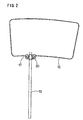
- a sphygmomanometer cuff 10A in accordance an embodiment of the present invention will be described with reference to Figs. 1 to 6.
- sphygmomanometer cuff 10A of the present embodiment includes an outer bag 11, an air bag 12 arranged within outer bag 11, and a tube 13 attached to air bag 12 and drawn out of outer bag 11 to extend outward.
- the outer bag is provided with an opening portion for replacing the air bag, and an anti-rotating member 20 is provided at a tube attaching portion 17 of air bag 12 for preventing rotation of air bag 12 within outer bag 11. Further, through opening portion 15 of outer bag 11, tube 13 of air bag 12 is drawn out of outer bag 11 to extend outward.
- Outer bag 11 is formed, for example, by joining the outer periphery of a pair of strip-like cloth material as mentioned above.
- Air bag 12 is arranged in the inner space provided on one side in the longitudinal direction (on the right side in Fig. 1) of the outer bag.
- the inside and outside of outer bag 11 are respectively provided with hook-and-loop fasteners 18a, 18b, which secure cuff 10A wrapped around a certain region of living body.
- the right side in the longitudinal direction of outer bag 11 is provided with opening portion 15 for replacing the air bag, having a length of width d plus width D. Since the part of width d of this opening portion 15 provides a tube exit (including anti-rotating member 20 here), this part is not provided with a fastener (not shown), whereas the part of width D is provided with a fastener.
- An example of fasteners includes one having protrusions on one side and recesses on the other side fitted in together, and one having teeth arranged oppositely to be mated together by means of a slider. Further, in stead of using a fastener, the opening portion may be closed up by means of a button.
- Air bag 12 is formed, for example, with a thin film of vinyl chloride and has tube attaching portion 17 where tube 13 is attached. Tube 13 is drawn out of outer bag 11 to extend outward and connect to a sphygmomanometer body.
- Anti-rotating member 20 provided at tube attaching portion 17 has such a shape as shown in Fig. 4. This anti-rotating member is fixed to tube attaching portion 17 of air bag 12, for example, by high-frequency welding at hatched part 20a shown in the drawing.
- tube attaching portion 17 is disposed at the part of width d of opening portion 15 of outer bag 11.
- Air bag 12 is accommodated in outer bag 11 with anti-rotating member 20 located at tube attaching portion 17, and the part of width D of opening portion 15 is closed by a fastener.
- anti-rotating member 20 abuts against opening portion 15, so that the torsion force from tube 13 does not act on air bag 12 to displace air bag 12 within outer bag 11.
- any inconvenience such as winding of air bag 12 and the like does not occur.
- width d that is, that part of opening portion 15 of outer bag 11 which is not provided with a fastener, provides an exit for tube 13, where anti-rotating member 20 is positioned. Therefore, when air bag 12 is put into outer bag 11, the exit of tube 13 can be easily found, and thus air bag 12 will not put into outer bag 11 inside out. In addition, it is possible to keep opening portion 15 closed by means of a fastener except when air bag 12 is taken out of outer bag 11.
- Figs. 5 and 6 show two modifications of the anti-rotating member.
- anti-rotating member 20 is provided only at tube attaching portion 17 of air bag 12.
- anti-rotating member 21 of air bag 12 is not only provided at tube attaching portion 17 but also expanded to the surface of air bag 12, wherein anti-rotating member 21 is hot-welded using high-frequency at hatched part 21a, and adhered to the surface of air bag 12. Since this anti-rotating member 21 extends to the outer side of air bag 12, any inconvenience such as winding of air bag 12 can be prevented even more effectively.
- anti-rotating member 22 of air bag 12 is not provided at tube attaching portion 17 but adhered to one face of air bag 12 in the vicinity of tube attaching portion 17.
- anti-rotating member 22 is formed of vinyl chloride sheet, rubber sheet or the like, having such a thickness that cannot be easily deformed.
- FIG. 7 shows a plan view of the inside of sphygmomanometer cuff 10B
- Fig. 8 shows a plan view of the air bag thereof
- Fig. 9 shows a partial side view of Fig. 8 seen from a direction of arrow A.
- opening portion 16 of outer bag 11 for replacing the air bag is provided across almost the entire width D1 of the space where air bag 12 is accommodated.
- Anti-rotating member 23 provided at tube attaching portion 17 of air bag 12 has a fastener function.
- anti-rotating member 23 forms a fastener having a protruding portion at one piece 23a and a recess portion at other piece 23b.
- the protruding portion and the recess portion can be fitted in together for closing.
- This anti-rotating member 23 can be engaged with the same type of fastener provided at opening portion 16 of outer bag 11.
- tube 13 is extended outward through opening portion 16 as shown in Fig. 7.
- any inconvenience such as winding of air bag 12 and the like can also be prevented by the effect of anti-rotating member 23, similar to the above noted cuff 10A.
- cuffs 10A and 10B of the above noted embodiments show that anti-rotating members 20-23 are provided only at either tube attaching portion 17 or the vicinity thereof. Alternatively, they may be provided at both of them to improve a function of preventing rotation of air bag 12.
- a sphygmomanometer cuff in accordance with the present invention provides that an outer bag has an opening portion for replacing an air bag, so that the air bag can easily be taken in and out through the opening portion to facilitate replacement of the air bag. Further, since the air bag has an anti-rotating member at a tube attaching portion or at the vicinity thereof, the air bag will not be displaced within the outer bag, and any inconvenience such as winding of the air bag and the like will not occur.
Landscapes
- Health & Medical Sciences (AREA)
- Life Sciences & Earth Sciences (AREA)
- Cardiology (AREA)
- Vascular Medicine (AREA)
- Engineering & Computer Science (AREA)
- Medical Informatics (AREA)
- Physics & Mathematics (AREA)
- Ophthalmology & Optometry (AREA)
- Biophysics (AREA)
- Pathology (AREA)
- Dentistry (AREA)
- Biomedical Technology (AREA)
- Heart & Thoracic Surgery (AREA)
- Physiology (AREA)
- Molecular Biology (AREA)
- Surgery (AREA)
- Animal Behavior & Ethology (AREA)
- General Health & Medical Sciences (AREA)
- Public Health (AREA)
- Veterinary Medicine (AREA)
- Measuring Pulse, Heart Rate, Blood Pressure Or Blood Flow (AREA)
Abstract
Description
Claims (7)
- A sphygmomanometer cuff (10A) having an air bag (12) arranged within an outer bag (11), from which a tube (13) attached to the air bag (12) is extended outward, characterized in that
an opening portion (15) is provided for said outer bag (11) allowing replacing of the air bag, that an anti-rotating member (20) for preventing rotation of the air bag (12) within the outer bag (11) is provided on at least one of a tube attaching portion (17) of said air bag (12) and the vicinity thereof, and that the tube (13) of the air bag (12) is drawn out of said outer bag (11) through the opening portion (15). - The sphygmomanometer cuff according to claim 1, characterized in that
a fastener for opening and closing said opening portion (15) is provided at said opening portion (15) of said outer bag (11) excluding a part through which said tube (13) passes. - The sphygmomanometer cuff according to claim 1, characterized in that
said anti-rotating member (20) includes a fastener. - The sphygmomanometer cuff according to claim 2, characterized in that
said anti-rotating member (20) includes a fastener, and that the fastener of this anti-rotating member (20) can be engaged with a fastener provided at said opening portion (15) of said outer bag (11). - The sphygmomanometer cuff according to claim 1, characterized in that
said anti-rotating member (20) is fixed to said tube attaching portion (17) of said air bag (12) by hot welding. - The sphygmomanometer cuff according to claim 1, characterized in that
said anti-rotating member (20) is expanded from said tube attaching portion (17) to the surface of said air bag (12). - The sphygmomanometer cuff according to claim 6, characterized in that
said anti-rotating member (20) is fixed to said tube attaching portion (17) of said air bag (12) by hot welding and adhered to the surface of said air bag (12).
Applications Claiming Priority (3)
| Application Number | Priority Date | Filing Date | Title |
|---|---|---|---|
| JP2000139334A JP3840875B2 (en) | 2000-05-12 | 2000-05-12 | Armband for sphygmomanometer |
| JP2000139334 | 2000-05-12 | ||
| PCT/JP2001/003915 WO2001085026A1 (en) | 2000-05-12 | 2001-05-10 | Cuff for blood pressure manometer |
Publications (3)
| Publication Number | Publication Date |
|---|---|
| EP1208794A1 true EP1208794A1 (en) | 2002-05-29 |
| EP1208794A4 EP1208794A4 (en) | 2002-11-20 |
| EP1208794B1 EP1208794B1 (en) | 2016-05-11 |
Family
ID=18646795
Family Applications (1)
| Application Number | Title | Priority Date | Filing Date |
|---|---|---|---|
| EP01930041.7A Expired - Lifetime EP1208794B1 (en) | 2000-05-12 | 2001-05-10 | Cuff for blood pressure manometer |
Country Status (5)
| Country | Link |
|---|---|
| US (1) | US6551249B2 (en) |
| EP (1) | EP1208794B1 (en) |
| JP (1) | JP3840875B2 (en) |
| CN (1) | CN1181785C (en) |
| WO (1) | WO2001085026A1 (en) |
Families Citing this family (17)
| Publication number | Priority date | Publication date | Assignee | Title |
|---|---|---|---|---|
| US8535233B2 (en) | 2000-09-25 | 2013-09-17 | Welch Allyn, Inc. | Blood pressure measuring apparatus |
| US7780603B2 (en) * | 2000-09-25 | 2010-08-24 | Welch Allyn, Inc. | Blood pressure measuring apparatus |
| US20080313282A1 (en) | 2002-09-10 | 2008-12-18 | Warila Bruce W | User interface, operating system and architecture |
| JP4342849B2 (en) * | 2003-06-19 | 2009-10-14 | 株式会社 サトウスポーツプラザ | Pressurized muscle strength increasing device, control device, and method executed by the control device |
| US7166077B2 (en) * | 2004-02-03 | 2007-01-23 | Pharma-Smart, Llc | Cuff for measurement of blood pressure |
| US20070060949A1 (en) * | 2005-09-09 | 2007-03-15 | Curry Ammie D | Inflatable tourniquet to aid in establishing intravenous access and method thereof |
| US8157951B2 (en) * | 2005-10-11 | 2012-04-17 | Applied Materials, Inc. | Capacitively coupled plasma reactor having very agile wafer temperature control |
| US7931606B2 (en) | 2005-12-12 | 2011-04-26 | Tyco Healthcare Group Lp | Compression apparatus |
| USD575871S1 (en) | 2006-09-11 | 2008-08-26 | Welch Allyn, Inc. | Universal port adapter for blood pressure measuring apparatus or the like |
| US8636678B2 (en) | 2008-07-01 | 2014-01-28 | Covidien Lp | Inflatable member for compression foot cuff |
| US20100298724A1 (en) * | 2009-05-19 | 2010-11-25 | Welch Allyn, Inc. | Recyclable or biodegradable blood pressure cuff |
| USD643536S1 (en) | 2009-05-19 | 2011-08-16 | Welch Allyn, Inc. | Blood-pressure cuff |
| US8652057B2 (en) | 2009-05-19 | 2014-02-18 | Welch Allyn, Inc. | Recyclable or biodegradable blood pressure cuff |
| US20130085427A1 (en) | 2011-09-29 | 2013-04-04 | Tyco Healthcare Group Lp | Compression garment having sealable bladder pocket |
| US9220422B2 (en) | 2012-11-19 | 2015-12-29 | Welch Allyn, Inc. | Blood pressure sleeve |
| JP2015066293A (en) * | 2013-09-30 | 2015-04-13 | ミナト医科学株式会社 | Armband for blood pressure measurement |
| CN111315284B (en) | 2017-11-02 | 2023-04-28 | 伟伦公司 | Connector for medical equipment |
Family Cites Families (11)
| Publication number | Priority date | Publication date | Assignee | Title |
|---|---|---|---|---|
| US3654931A (en) | 1970-02-11 | 1972-04-11 | Kidde & Co Walter | Disposable tourniquet cover |
| US3669096A (en) * | 1970-04-07 | 1972-06-13 | Mathew Hurwitz | Self-donning sphygmomanometer cuff |
| US3906937A (en) * | 1972-10-25 | 1975-09-23 | Para Medical Instr Corp | Blood pressure cuff and bladder and apparatus embodying the same |
| US4745924A (en) * | 1986-06-30 | 1988-05-24 | Spacelabs, Inc. | Blood pressure cuff |
| JPH0345687Y2 (en) * | 1986-08-18 | 1991-09-26 | ||
| US4727885A (en) * | 1986-12-24 | 1988-03-01 | Spacelabs, Inc. | Self applied blood pressure cuff |
| JPH02116406A (en) | 1988-10-24 | 1990-05-01 | Brother Ind Ltd | tool unit |
| JPH02116406U (en) * | 1989-03-07 | 1990-09-18 | ||
| JPH0345687A (en) | 1989-07-13 | 1991-02-27 | Izumi Shoji Kk | Wall surface-stabilizing liquid composition |
| US5797851A (en) | 1997-02-18 | 1998-08-25 | Byrd; Timothy N. | Medical bladder cover |
| US6245023B1 (en) * | 1999-08-19 | 2001-06-12 | Critikon Company, Llc | Conical blood pressure cuff with rectangular bladder |
-
2000
- 2000-05-12 JP JP2000139334A patent/JP3840875B2/en not_active Expired - Lifetime
-
2001
- 2001-05-10 WO PCT/JP2001/003915 patent/WO2001085026A1/en not_active Ceased
- 2001-05-10 CN CNB01801223XA patent/CN1181785C/en not_active Expired - Lifetime
- 2001-05-10 US US10/009,193 patent/US6551249B2/en not_active Expired - Lifetime
- 2001-05-10 EP EP01930041.7A patent/EP1208794B1/en not_active Expired - Lifetime
Also Published As
| Publication number | Publication date |
|---|---|
| CN1372448A (en) | 2002-10-02 |
| WO2001085026A1 (en) | 2001-11-15 |
| EP1208794B1 (en) | 2016-05-11 |
| US20020161303A1 (en) | 2002-10-31 |
| EP1208794A4 (en) | 2002-11-20 |
| JP2001314382A (en) | 2001-11-13 |
| JP3840875B2 (en) | 2006-11-01 |
| CN1181785C (en) | 2004-12-29 |
| US6551249B2 (en) | 2003-04-22 |
Similar Documents
| Publication | Publication Date | Title |
|---|---|---|
| EP1208794B1 (en) | Cuff for blood pressure manometer | |
| US6149600A (en) | Blood pressure measuring device | |
| EP1970002B1 (en) | Blood pressure meter cuff and blood pressure meter with the same | |
| US10299726B2 (en) | Bodily information measurement apparatus | |
| EP1688089B1 (en) | Cuff for blood pressure monitor, manufacturing method thereof and blood pressure monitor | |
| JP3952957B2 (en) | Cuff for wrist blood pressure monitor | |
| EP1693001A1 (en) | Blood pressure monitor and corresponding cuff | |
| KR101034390B1 (en) | Cuff for Sphygmomanometer | |
| CN111655137A (en) | Butterfly shape cover | |
| WO2017175618A1 (en) | Pulse wave detection device and biometric information measurement device | |
| EP1702562A1 (en) | Blood pressure monitor cuff and blood pressure monitor | |
| JPH0234143A (en) | Blood pressure gauge for wrist | |
| JP3591302B2 (en) | Wrist sphygmomanometer cuff | |
| CN108024735B (en) | Pulse wave detection device | |
| CN107920756B (en) | Pulse wave detection device | |
| ITMI20000370U1 (en) | IDENTIFIER BRACELET FOR PATIENTS SUITABLE FOR USE IN HOSPITALS PLACES OF CARE AND SIMILAR | |
| CN213993549U (en) | Electronic sphygmomanometer cuff coat | |
| JPH0546411Y2 (en) | ||
| JPH07255687A (en) | Cuff of finger sphygmomanometer | |
| JPH0265838A (en) | Cuff for hemomanometer | |
| JP2005270354A (en) | Clip board | |
| JPH0522161Y2 (en) | ||
| JPS61238227A (en) | Cuff band of digital hemomanometer | |
| JPH0595503U (en) | Electronic blood pressure cuff | |
| JPH0232803U (en) |
Legal Events
| Date | Code | Title | Description |
|---|---|---|---|
| PUAI | Public reference made under article 153(3) epc to a published international application that has entered the european phase |
Free format text: ORIGINAL CODE: 0009012 |
|
| 17P | Request for examination filed |
Effective date: 20020207 |
|
| AK | Designated contracting states |
Kind code of ref document: A1 Designated state(s): AT BE CH CY DE DK ES FI FR GB GR IE IT LI LU MC NL PT SE TR |
|
| A4 | Supplementary search report drawn up and despatched |
Effective date: 20021008 |
|
| AK | Designated contracting states |
Kind code of ref document: A4 Designated state(s): AT BE CH CY DE DK ES FI FR GB GR IE IT LI LU MC NL PT SE TR |
|
| RIC1 | Information provided on ipc code assigned before grant |
Free format text: 7A 61B 5/022 A, 7A 61B 17/135 B |
|
| RAP1 | Party data changed (applicant data changed or rights of an application transferred) |
Owner name: OMRON HEALTHCARE CO., LTD. |
|
| RBV | Designated contracting states (corrected) |
Designated state(s): DE FR GB IT |
|
| RAP1 | Party data changed (applicant data changed or rights of an application transferred) |
Owner name: OMRON HEALTHCARE CO., LTD. |
|
| 17Q | First examination report despatched |
Effective date: 20070306 |
|
| APBK | Appeal reference recorded |
Free format text: ORIGINAL CODE: EPIDOSNREFNE |
|
| APBN | Date of receipt of notice of appeal recorded |
Free format text: ORIGINAL CODE: EPIDOSNNOA2E |
|
| APBR | Date of receipt of statement of grounds of appeal recorded |
Free format text: ORIGINAL CODE: EPIDOSNNOA3E |
|
| APAO | Information on interlocutory revision modified |
Free format text: ORIGINAL CODE: EPIDOSCIRAPE |
|
| APBD | Information on interlocutory revision deleted |
Free format text: ORIGINAL CODE: EPIDOSDIRAPE |
|
| APBV | Interlocutory revision of appeal recorded |
Free format text: ORIGINAL CODE: EPIDOSNIRAPE |
|
| GRAP | Despatch of communication of intention to grant a patent |
Free format text: ORIGINAL CODE: EPIDOSNIGR1 |
|
| INTG | Intention to grant announced |
Effective date: 20150617 |
|
| RIN1 | Information on inventor provided before grant (corrected) |
Inventor name: YAMAMOTO, NORIHITO Inventor name: ASHIDA, TAMEO |
|
| GRAP | Despatch of communication of intention to grant a patent |
Free format text: ORIGINAL CODE: EPIDOSNIGR1 |
|
| INTG | Intention to grant announced |
Effective date: 20151109 |
|
| GRAS | Grant fee paid |
Free format text: ORIGINAL CODE: EPIDOSNIGR3 |
|
| GRAA | (expected) grant |
Free format text: ORIGINAL CODE: 0009210 |
|
| RAP1 | Party data changed (applicant data changed or rights of an application transferred) |
Owner name: OMRON HEALTHCARE CO., LTD. |
|
| RIN1 | Information on inventor provided before grant (corrected) |
Inventor name: ASHIDA, TAMEO Inventor name: YAMAMOTO, NORIHITO |
|
| AK | Designated contracting states |
Kind code of ref document: B1 Designated state(s): DE FR GB IT |
|
| REG | Reference to a national code |
Ref country code: GB Ref legal event code: FG4D |
|
| REG | Reference to a national code |
Ref country code: DE Ref legal event code: R096 Ref document number: 60149937 Country of ref document: DE |
|
| PG25 | Lapsed in a contracting state [announced via postgrant information from national office to epo] |
Ref country code: IT Free format text: LAPSE BECAUSE OF FAILURE TO SUBMIT A TRANSLATION OF THE DESCRIPTION OR TO PAY THE FEE WITHIN THE PRESCRIBED TIME-LIMIT Effective date: 20160511 |
|
| REG | Reference to a national code |
Ref country code: DE Ref legal event code: R097 Ref document number: 60149937 Country of ref document: DE |
|
| PLBE | No opposition filed within time limit |
Free format text: ORIGINAL CODE: 0009261 |
|
| STAA | Information on the status of an ep patent application or granted ep patent |
Free format text: STATUS: NO OPPOSITION FILED WITHIN TIME LIMIT |
|
| 26N | No opposition filed |
Effective date: 20170214 |
|
| GBPC | Gb: european patent ceased through non-payment of renewal fee |
Effective date: 20170510 |
|
| REG | Reference to a national code |
Ref country code: FR Ref legal event code: ST Effective date: 20180131 |
|
| PG25 | Lapsed in a contracting state [announced via postgrant information from national office to epo] |
Ref country code: GB Free format text: LAPSE BECAUSE OF NON-PAYMENT OF DUE FEES Effective date: 20170510 |
|
| PG25 | Lapsed in a contracting state [announced via postgrant information from national office to epo] |
Ref country code: FR Free format text: LAPSE BECAUSE OF NON-PAYMENT OF DUE FEES Effective date: 20170531 |
|
| PGFP | Annual fee paid to national office [announced via postgrant information from national office to epo] |
Ref country code: DE Payment date: 20200529 Year of fee payment: 20 |
|
| REG | Reference to a national code |
Ref country code: DE Ref legal event code: R071 Ref document number: 60149937 Country of ref document: DE |