EP1207621A2 - Transversal surface acoustic wave filter - Google Patents
Transversal surface acoustic wave filter Download PDFInfo
- Publication number
- EP1207621A2 EP1207621A2 EP01402934A EP01402934A EP1207621A2 EP 1207621 A2 EP1207621 A2 EP 1207621A2 EP 01402934 A EP01402934 A EP 01402934A EP 01402934 A EP01402934 A EP 01402934A EP 1207621 A2 EP1207621 A2 EP 1207621A2
- Authority
- EP
- European Patent Office
- Prior art keywords
- surface acoustic
- acoustic wave
- interdigital transducer
- reflector
- idt
- Prior art date
- Legal status (The legal status is an assumption and is not a legal conclusion. Google has not performed a legal analysis and makes no representation as to the accuracy of the status listed.)
- Granted
Links
Images



Classifications
-
- H—ELECTRICITY
- H03—ELECTRONIC CIRCUITRY
- H03H—IMPEDANCE NETWORKS, e.g. RESONANT CIRCUITS; RESONATORS
- H03H9/00—Networks comprising electromechanical or electro-acoustic elements; Electromechanical resonators
- H03H9/46—Filters
- H03H9/64—Filters using surface acoustic waves
- H03H9/6423—Means for obtaining a particular transfer characteristic
- H03H9/6433—Coupled resonator filters
- H03H9/6436—Coupled resonator filters having one acoustic track only
-
- H—ELECTRICITY
- H03—ELECTRONIC CIRCUITRY
- H03H—IMPEDANCE NETWORKS, e.g. RESONANT CIRCUITS; RESONATORS
- H03H9/00—Networks comprising electromechanical or electro-acoustic elements; Electromechanical resonators
- H03H9/02—Details
- H03H9/125—Driving means, e.g. electrodes, coils
- H03H9/145—Driving means, e.g. electrodes, coils for networks using surface acoustic waves
- H03H9/14502—Surface acoustic wave [SAW] transducers for a particular purpose
- H03H9/14505—Unidirectional SAW transducers
-
- H—ELECTRICITY
- H03—ELECTRONIC CIRCUITRY
- H03H—IMPEDANCE NETWORKS, e.g. RESONANT CIRCUITS; RESONATORS
- H03H9/00—Networks comprising electromechanical or electro-acoustic elements; Electromechanical resonators
- H03H9/02—Details
- H03H9/125—Driving means, e.g. electrodes, coils
- H03H9/145—Driving means, e.g. electrodes, coils for networks using surface acoustic waves
- H03H9/14517—Means for weighting
- H03H9/14526—Finger withdrawal
-
- H—ELECTRICITY
- H03—ELECTRONIC CIRCUITRY
- H03H—IMPEDANCE NETWORKS, e.g. RESONANT CIRCUITS; RESONATORS
- H03H9/00—Networks comprising electromechanical or electro-acoustic elements; Electromechanical resonators
- H03H9/02—Details
- H03H9/125—Driving means, e.g. electrodes, coils
- H03H9/145—Driving means, e.g. electrodes, coils for networks using surface acoustic waves
- H03H9/14544—Transducers of particular shape or position
- H03H9/14552—Transducers of particular shape or position comprising split fingers
-
- H—ELECTRICITY
- H03—ELECTRONIC CIRCUITRY
- H03H—IMPEDANCE NETWORKS, e.g. RESONANT CIRCUITS; RESONATORS
- H03H9/00—Networks comprising electromechanical or electro-acoustic elements; Electromechanical resonators
- H03H9/46—Filters
- H03H9/64—Filters using surface acoustic waves
- H03H9/6423—Means for obtaining a particular transfer characteristic
- H03H9/643—Means for obtaining a particular transfer characteristic the transfer characteristic being determined by reflective or coupling array characteristics
Definitions
- the present invention relates to a transversal surface acoustic wave filter and more particularly to a transversal surface acoustic wave filter in which a reflector or a reflection end-face is provided on the outer side in the surface acoustic wave propagation direction of at least one of an interdigital transducer (hereinafter, referred to as IDT) on the input side and an IDT on the output side.
- IDT interdigital transducer
- the transversal surface acoustic wave filters are characteristic in that the ground delay time deviation curve is flat, and the attenuation near the pass band is sufficient. Accordingly, the transversal surface acoustic wave filters are suitable for use as IF filters.
- the IF filters in portable telephones in the CDMA system have been required to have a wide band characteristic.
- the transversal surface acoustic wave filters can easily cope with such requirement for the wide band characteristic.
- the transversal surface acoustic wave filters have a large insertion loss, and the elements must have a large size.
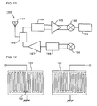
- Fig. 12 is a schematic plan view of an example of a conventional transversal surface acoustic wave filter.
- an IDT 101 on the input side and an IDT 102 on the output side are arranged in the surface acoustic wave propagation direction on a piezoelectric substrate.
- the IDT on the input side is thinning-out weighted so that a desired characteristic can be obtained, and moreover, a unidirectional electrode 103 is formed inside the IDT to reduce the insertion loss.
- Fig. 13 is a schematic plan view of another example of the conventional transversal surface acoustic wave filter, and illustrates the configuration disclosed in Japanese Unexamined Patent Application Publication No. 11-186865.
- a transversal surface acoustic wave filter 201 an IDT 203 on the input side, an IDT 204 on the output side, and a reflector 205 are arranged in the surface acoustic wave propagation direction, and moreover, similarly, an IDT 206 on the input side, an IDT 207 on the output side, and a reflector 208 are formed and arranged in the surface acoustic wave propagation direction at the side of the configuration in which the IDT 203 on the input side, the IDT 204 on the output side, and the reflector 205 are arranged.
- the polarities of the IDTs 206 and 207 are reverse to those of the IDTs 203 and 204.
- the IDTs 203 and 206 on the input side are connected in common, that is, are connected to an input terminal IN.
- the IDTs 204 and 207 are connected in common, that is, are connected to an output terminal OUT.
- the IDT 203 on the input side and the IDT 204 on the output side are arranged with a separation of W1
- the IDT 206 on the input side and the IDT 207 on the output side are arranged with a separation of W3.
- the distances W1 and W2 are equal to each other.
- an electrical signal is input to the input IDTs 203 and 206 and is converted to surface acoustic waves. These surface acoustic waves are propagated toward the output IDTs 204 and 207.
- the output IDTs 204 and 207 are configured so that the surface acoustic waves can pass through the output IDTs 204 and 207 while the waves are not converted to electrical signals.
- the surface acoustic waves passed through the output IDTs 204 and 207 are reflected by the reflectors 205 and 208.
- the reflected surface acoustic waves are converted to electrical signals by the output IDTs 204 and 207, and are output therefrom.
- the transversal surface acoustic wave filter 201 shown in Fig. 13 utilizes the weighting of the input IDTs 203 and 204 and the output IDTs 206 and 207, the characteristics determined by the position of the reflection electrode of the unidirectional electrode or the like, and moreover, the reflection characteristics of the reflectors 205 and 208. Thus, the attenuation near the pass band can be increased.
- the bandwidth of the pass band of the transversal surface acoustic wave filter shown in Fig. 12 is determined mainly by the number of the electrode finger pairs of each IDT.
- a required bandwidth must be considered. Accordingly, it has been difficult to reduce the number of the paired electrode fingers of each IDT.
- the surface acoustic wave filter 201 is also required to increase the number of the paired electrode fingers of the IDTs 203 and 204 and 205 and 206 on the input and output sides similarly to the transversal surface acoustic wave filter shown in Fig. 12. Thus, the insertion loss is large, and it is difficult to reduce the size of the elements.
- a transversal surface acoustic wave filter which comprises a piezoelectric substrate, an interdigital transducer on the input side and an interdigital transducer on the output side arranged in the surface acoustic wave propagation direction on the piezoelectric substrate, and a reflector disposed on the outer side in the surface acoustic wave propagation direction of one of the interdigital transducer on the input side and the interdigital transducer on the output side, the interdigital transducer adjacent to the reflector being weighted, wherein while a surface acoustic wave passes through the interdigital transducer adjacent to the reflector and while the surface acoustic wave reflecting from the reflector passes through the interdigital transducer adjacent to the reflector, the surface acoustic wave is converted to first and second electrical signals, respectively, and the distance between the reflector and the interdigital transducer adjacent to the reflector is set
- the absolute value of the integral value of excitation intensity of the electrode finger pairs of the first group is larger than that of the electrode finger pairs of the second group.
- the excitation intensity integral value of the electrode finger pairs of the first group is at least 80% of the excitation intensity integral value of the electrode finger pairs of an assumed first group comprising a normal type interdigital transducer.
- the size in the surface acoustic wave propagation direction of the reflector is set to be shorter than that of the interdigital transducer adjacent to the reflector.
- the reflectivity of the reflector measured at the center frequency is substantially 100%.
- the distance L between the weighted interdigital transducer and the reflector is in the range expressed by (n/2 - 1/8) ⁇ ⁇ 0.04 ⁇ in which ⁇ is the length of one period in the weighted interdigital transducer, and n is a natural number.
- the transversal surface acoustic wave filter further comprises a reflector disposed on the outer side in the surface acoustic wave propagation direction of the interdigital transducer opposite to the weighted interdigital transducer.
- a transversal surface acoustic wave filter which comprises a piezoelectric substrate, and an interdigital transducer on the input side and an interdigital transducer on the output side arranged in the surface acoustic wave propagation direction on the piezoelectric substrate, the end-face of the piezoelectric substrate on the outer side of one of the interdigital transducer on the input side and the interdigital transducer on the output side constituting a reflection end-face, the interdigital transducer adjacent to the end-face being weighted, wherein while a surface acoustic wave passes through the weighted interdigital transducer adjacent to the reflection end-face and while the surface acoustic wave reflecting from the reflection end-face passes through the weighted interdigital transducer, the surface acoustic wave is converted to first and second electrical signals, respectively, and the distance between the reflection end-face and the interdigital transducer adjacent to the reflection end-face
- the absolute value of the integral value of excitation intensity of the electrode finger pairs of the first group is larger than that of the electrode finger pairs of the second group.
- the excitation intensity integral value of the electrode finger pairs of the first group is at least 80% of the excitation intensity integral value of the electrode finger pairs of an assumed first group comprising a normal type interdigital transducer.
- the distance L between the weighted interdigital transducer and the reflector is in the range expressed by n ⁇ /2 ⁇ 0.04 ⁇ in which n is or a natural number.
- the weighted interdigital transducer contains a split electrode. More preferably, all of the electrode fingers of the weighted interdigital transducer are split electrodes.
- the transversal surface acoustic wave filter further comprises an electrode applicable to mechanically reflect a surface acoustic wave in the weighted interdigital transducer.
- a communications device including one of the above-described transversal surface acoustic wave filters as a band-pass filter is provided.
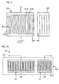
- Fig. 1 is a plan view of a transversal surface acoustic wave filter according to a first embodiment of the present invention.
- a surface acoustic wave filter 1 contains a piezoelectric substrate 2 having a rectangular sheet shape.
- the material constituting the piezoelectric substrate 2 is not specially limited.
- piezoelectric single crystals such as LiNbO 3 , LiTaO 3 , and Li 2 B 4 O 7
- piezoelectric ceramics materials such as lead titanate zirconate type ceramics and so forth can be used.
- the piezoelectric substrate 2 may be an insulating substrate made of alumina or the like having a piezoelectric thin film such as a ZnO thin film or the like formed thereon.
- the piezoelectric substrate 2 is made of Li 2 B 4 O 7 of a 45°X-cut Z-propagation type.
- An electrode configuration made of Al, shown in Fig. 1, is formed on the upper face of the piezoelectric substrate 2.
- This electrode configuration contains an IDT 3 on the input side, an IDT 4 on the output side, and a reflector 5.
- the input IDT 3 and the output IDT 4 are arranged in the surface acoustic wave propagation direction.
- the reflector 5 is disposed on the outer side in the surface acoustic wave propagation direction of the output IDT 4.
- the reflector 5 is a grating reflector in which both ends of a plurality of the electrode fingers are short-circuited.
- the input IDT 3 is a unidirectional IDT formed by the publicly known method. However, since the unidirectivity is not complete, a sound absorbing member 6 is disposed on the outer side in the surface acoustic wave propagation direction of the input IDT 3. In this embodiment, the sound absorbing member 6 is formed by coating silicone resin. The material constituting the sound absorbing member 6 is not specially limited.
- the IDT 3 is set on the input side
- the IDT 4 is set on the output side.
- the IDTs 3 and 4 may be set on the output and input sides, respectively.
- the surface acoustic wave filter 1 is designed so as to have a center frequency of 380 MHz.
- the electrode fingers of the IDTs 3 and 4, and the reflector 5 are schematically shown.
- the number of the electrode finger pairs of the input IDT 3 is 230, that of the output IDT 4 is 90, and that of the reflector 5 is 60.
- the input IDT 3 comprises unidirectional electrodes each containing electrodes 3a and 3b having different widths. Split electrodes of which the electrode fingers each comprises two electrodes having the same width may be combined with the unidirectional electrodes to be arranged.
- the configuration of the unidirectional electrodes is not limited to that shown in Fig. 1. Other configurations may be employed.
- the output IDT 4 comprises split electrodes which cause no mechanical reflection, as shown in Fig. 1. That is, the IDT 4 is formed by using split electrodes in which each electrode finger comprises two electrodes 4a and 4b having the same width.
- All of the electrode fingers of the IDT 4 comprise split electrodes. According to the present invention, all of the electrode fingers of the IDT 4, which is adjacent to the reflector 5, do not necessarily comprise split electrodes. That is, electrode fingers which present mechanical reflection to some degree and are not split electrodes, that is, electrode fingers each comprising a single electrode may be arranged in the IDT 4.
- the IDTs 3 and 4 are thinning-out weighted so as to have a desired impulse intensity distribution.
- Figs. 2A and 2B illustrate the weighting of the input IDT 3 and the output IDT 4, respectively.
- the position in the surface acoustic wave propagation direction is plotted on the abscissa, and the excitation intensity of each electrode finger pair in the IDTs 3 and 4 is plotted on the ordinate in Figs. 2A and 2B, respectively.
- the output IDT 4 is weighted so that the excitation intensity distribution becomes almost the same as the half of the excitation intensity distribution of the input IDT 3 produced on one side of the center in the surface acoustic wave propagation direction.
- the positions of the respective electrode finger pairs are plotted on the abscissas.
- the positions of the electrode finger pairs of the IDT 3 are plotted at the same interval in the range of - 2.5 ⁇ to 2.5 ⁇ .
- the excitation intensity of the respective electrode pairs is plotted on the ordinate. It is to be noted that the intensity values are obtained by standardization by use of the excitation intensities of the respective electrode pairs of an assumed normal type IDT.
- Figs. 2A and 2B show the intensities of the plus impulses, respectively.
- the negative intensities shown in Figs. 2A and 2B mean that the phases of the reception signals (or transmission signals) are inverted, respectively.
- the excitation intensities may be controlled to be higher or lower by using a thinning-out ratio, respectively.
- the excitation intensities in the negative regions can be produced by inverting the polarities of the electrode fingers in the IDTs, that is, inverting the phases of the signals.
- the surface acoustic wave filter of this embodiment when an input signal is applied to the input IDT 3, a surface acoustic wave is excited. Most of the surface acoustic wave propagates toward the output IDT 4, since the IDT 3 comprises the unidirectional electrodes. A first electrical signal based on the propagated surface acoustic wave is output from the output IDT 4 while the wave passes through the output IDT 4. Additionally, the surface acoustic wave passed through the output IDT 4 is reflected by the reflector 5. The surface acoustic wave reflected therefrom reaches the output IDT 4 again. A second electrical signal based on the reflected surface acoustic wave is also output from the output IDT 4.
- the first and second electrical signals are output from the output IDT 4.
- the operation carried out in the IDT 4 when the electrical signals are output as described above will be described in more detail.
- one impulse propagated from a half of an electrode pair in the input IDT 3 to enter the output IDT 4 will be discussed.
- the surface acoustic wave caused by the one impulse is propagated and reaches the output IDT 4.
- the surface acoustic wave advances from the electrode positioned near the input IDT 3 of the output IDT 4 toward the reflector 5.
- a part of the energy of the surface acoustic wave caused by the impulse is output as the first electrical signal sequentially with the lapse of time when the surface acoustic wave caused by the impulse passes through the IDT 4, according to the weighting of the IDT 4.
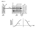
- the weighting of the output IDT 4 is reproduced in the intensity of the impulse appearing sequentially with the lapse of time. That is, the weighting of the output IDT 4 is reproduced as the function of time.
- the surface acoustic wave for the impulse, passed through the output IDT 4, is reflected by the reflector 5, and advances from the reflector 5 toward the output IDT 4.
- the reflected surface acoustic wave is propagated from the electrode positioned near the reflector 5 of the output IDT 4 toward the electrode positioned remotely from the reflector 5, similarly to the above-described operation.
- the energy of the reflected surface acoustic wave is output as the second electrical signal sequentially with the lapse of time when the surface acoustic wave passes through each electrode, according to the weighting of the electrodes.
- the second electrical signal is output with substantially no time lag behind the above-described excitation intensity distribution show in Fig. 2B, as an electrical signal having the excitation intensity distribution shown in Fig. 2B and inverted with respect to the time axis.
- the second electrical signal based on the reflected surface acoustic wave can be utilized.
- an impulse equivalent to that obtained by using an IDT with the number of electrode finger pairs equal to be twice that of the IDT 4 can be output from the output IDT 4.
- the interval between the IDT 4 and the reflector 5 is set so that the two-fold impulse can be output from the output IDT 4.
- the interval between the output IDT 4 and the reflector 5 is adjusted so as to attain the same characteristics as those obtained if the same IDT as the output IDT 4 is provided in the position where the IDT and the IDT 4 are symmetrical with respect to the imaginary reflection plane of the reflector 5.
- the output IDT 4 comprises split electrodes which do not mechanically reflect a surface acoustic wave
- the surface acoustic wave causes no undesirable mechanical reflection when the wave enters and passes through the output IDT 4.
- the symmetry of the impulse caused by the surface acoustic wave first passing through the output IDT and the impulse caused by the surface acoustic wave reflected by the reflector 5 is enhanced. This facilitates the design of the output IDT 4.
- the reflector 5 is arranged only on the outer side in the surface acoustic wave propagation direction of the output IDT 4, and thereby, the characteristics can be improved as described above.
- a second reflector instead of the sound absorbing member 6, may be disposed on the outer side in the surface acoustic wave propagation direction of the input IDT 3.
- the second reflector In the case in which the second reflector is provided, a surface acoustic wave is trapped between the reflector 5 and the second reflector. This may cause a resonance phenomenon. In some cases, the resonant impulse makes ineffective the weighting of the impulse which should be output from the output IDT 4. Thus, it is preferably not to provide the second reflector.
- the above-described resonance phenomenon can be suppressed as much as possible by forming the second reflector so that the reflection ratio at the center frequency of the filter is up to about 20%.
- the insertion loss in the pass band can be reduced as follows.
- the weighting of the input IDT 3 and the output IDT 4 is optimized including the impulse operation by positively utilizing the dwell time of the impulse caused by the weak resonance.
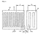
- Fig. 4 is a schematic plan view of a first modification example of the surface acoustic wave filter according to the above-described embodiment.
- Fig. 4 shows an IDT 14 on the output side and a reflector 15 only with the other elements being omitted.
- ⁇ in Fig. 4 is defined as follows.
- the ⁇ written on the upper side of the output IDT 14 in Fig. 4 is substantially equal to the wavelength of a surface acoustic wave which corresponds to a desired center frequency of the surface acoustic wave filter.
- ⁇ r written on the upper side of the reflector 15 is made slightly different from the ⁇ in order to correct the difference between the velocities of the surface acoustic wave, caused by the different electrode pitches in the reflector 15.
- the wavelength ⁇ r of the reflector 15 can be desirably changed, provided that the reflection at a desired frequency is satisfactory.
- the separation L between the output IDT 14 adjacent to the reflector 15 and the reflector 15 is defined by using the wavelength ⁇ of the output IDT 14 as a reference.
- the interval L is expressed as the distance between the centers of the electrode fingers of the IDT 14 and the reflector 15. That is, since the IDT 14 contains split electrodes, the center between the two electrodes 14a and 14b is defined as the center of the electrode fingers.
- the separation L is expressed by the distance from the center between the electrodes 14a and 14b to the center of the electrode finger 15a positioned on the output IDT 14 side of the reflector 15.
- the separation L is expressed by the distance between the center in the surface acoustic wave propagation direction of the single electrode and the center of the electrode finger 15a of the reflector 15. In the modification example shown in Fig. 4, the interval L is 0.875 ⁇ .
- the basic operational principle of the surface acoustic wave filter of this modification example is the same as that of the surface acoustic wave filter 1 of the above-described first embodiment.
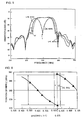
- the solid line in Fig. 5 represents the attenuation frequency characteristic of the surface acoustic wave filter of this modification example.
- the characteristic is significantly changed, caused by the different spacings L, as clearly seen in Fig. 5. This means that the difference between the phase of the surface acoustic wave entering the reflector 15 and the phase thereof after the reflection considerably affects the characteristic.
- Fig. 6 shows the results.
- the distance L is plotted on the abscissa, and the frequency position of the pole of the ripple in the pass band is plotted on the ordinate.
- the position of the ripple in the pass band is changed in the range of 0.5 ⁇ and has a periodicity, caused by the varied spacing L.
- the spacing L at which the ripple in the pass band positions at the center frequency (380 MHz) can be expressed by (n/2 + 1/8) ⁇ in which n is a natural number).
- the spacing L at which the ripple positions farthest from the pass band can be expressed by (n/2 - 1/8) ⁇ .
- the bandwidth is reduced, due to the ripple.
- the present invention by optimization of the distance L to shift the in-band ripple to the outside of the band, a satisfactory characteristic in the band can be obtained, and also, the characteristic having a narrow bandwidth can be provided without the number of electrode finger pairs being increased. In other words, a desired bandwidth can be secured, and also, the characteristic with an improved ripple near the pass band can be obtained by use of a decreased number of electrode finger pairs.
- a filter with good characteristics in which the attenuation near the pass band is superior, and no ripples are produced in the band, and of which the size is reduced can be realized by using the SAW filter of the first embodiment and setting the distance L between the output IDT 61 and the reflector 62 to satisfy (n/2 - 1/8) ⁇ ⁇ 0.04 ⁇ .
- a method in which the position of the reflector 15 is shifted by ⁇ /8 from a predetermined position in the surface acoustic wave propagation direction wherein the phases of an incident wave and the reflected wave are coincident with each other has been already used in unidirectional converters.
- a unidirectional converter is realized, in which reflection strips are arranged between the IDT stages in a surface acoustic wave filter having a ladder circuit configuration, the respective reflection stripes are disposed so as to be shifted by ⁇ /8 from the positions n ⁇ /2 distant from the respective IDTs.
- the reflectors need to be dispersed in the IDT. Moreover, if it is desired that a part of the IDT constitutes a unidirectional converter, the reflector needs to be inserted in the part of the IDT. Moreover, the reflection quantity caused by the reflector must not be excessively large, so that the IDT on the outer side in the surface acoustic wave propagation direction of the part having the reflector disposed therein can effectively act.
- the time of the impulse response to electrical signals to be output from the output IDTs 4 and 14, when observed along the time axis, is prolonged to the time taken by twice the number of the practical electrode finger pairs.
- the weighting of each of the output IDTs 4 and 14 is made symmetrically with respect to the equivalent reflection plane in the reflector. That is, the time of the impulse response is prolonged to be two-fold by weighting as shown in Fig. 3, and the impulse response is carried out by using the weighting symmetric with respect to the reflection plane.
- a satisfactory frequency characteristic can be realized.
- the phases of the impulses of the incident and reflected waves are in succession without overlapping on the time axis and have phases matched at a desired frequency by controlling the spacing L.
- Fig. 7 illustrates a second modification example according to the present invention, and shows a thinning-out weighting distribution for the output IDT 4.
- the second modification example is the same as the first embodiment except that the thinning-out weighting of the output IDT 4 is changed.
- the second modification example will be described with reference to the configuration of the first embodiment shown in Fig. 1.
- the position in the output IDT 4 in the surface acoustic wave propagation direction is plotted on the abscissa in Fig. 7, similarly to Fig. 2.
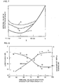
- the positions of the electrode finger pairs of the output IDT are set at the same spacing in the range of - 1.5 ⁇ to 0.
- the excitation intensity integral value is plotted on the ordinate.
- the integral value F(x) at the position X is expressed by in which f(x) is the excitation intensity distribution shown in Fig. 2.
- This weighting distribution is named weighting P.
- the integral value of the excitation intensity obtained when the weighting P is employed is represented by the solid line.
- the second modification example uses the weighting carried out in the embodiment of Fig. 2 as an initial value, and optimizes it using thinning-out weighting. Referring to the optimization, the weighting of the input IDT 3 is fixed, and the output IDT 4 is optimized. The results of the optimization depend on objective characteristics. In this case, as examples of the optimization results, weighting distributions Q and R are shown, which are represented by the alternate long and short dash line Q and the broken line R in Fig. 7, respectively.
- the optimized weighting distribution does not conform to a simple function such as sin X / X, but variously changes depending on desired characteristics.
- the electrode finger pairs of the output IDT 4 are equally grouped into three groups in the surface acoustic wave propagation direction, and the groups are named first, second, and third groups in the order from the reflector 5 side.
- the integral value of the excitation intensity of the first group is plotted on the abscissa in Fig 8. In this case, the integral value of the excitation intensity of the first group is expressed by the ratio (%) thereof based on that of the normal type IDT.
- the loss in the pass band (dots) and the deviation of ripples (hollow boxes) of the weighted first group are plotted on the ordinate.
- the optimization of the weighting is carried out with an upper limit being provided for the integral value of the excitation intensity.
- the results are plotted in Fig. 8. As seen in Fig. 8, when the excitation intensity integral value of the first group is at least 80%, the loss in the pass band and the deviation of ripples are small. Accordingly, preferably, the excitation intensity integral value of the first group is set to be at least 80% of that of the normal type IDT.
- the excitation intensity integral value of the first group is set to be at least 80% as the relative value, and thereby, the characteristic in the pass band is improved.
- the reason may be as follows.
- the first group is configured so that the electrical signal of the impulse generated after the reflection by the reflector 5 and output from the output IDT 4 is practically prolonged to be two-fold, and the weighting is carried out, repeatedly with respect to the equivalent reflection plane in the reflector. If the weighting is made so that a part of the first group having the highest excitation intensity is positioned farthest from the reflector, the impulse train determined by the output IDT 4 will present two peaks having the highest value, arranged side by side along the time axis.
- the above-description does not mean that when the integral value is less than 80 %, a sufficient characteristic can not be obtained.
- the optimization is possible in the input IDT 3. Even if the filter has a characteristic insufficient to obtain a good in-band characteristic only by the impulses generated in the output IDT 4, the filter can be designed so that the input IDT 3 compensates the deficiencies of the output IDT 4 by weighting of the input IDT 3 for excitation and combination with a unidirectional electrode.
- Fig. 9 is a schematic plan view illustrating a third modification example of the surface acoustic wave filter of the first embodiment shown in Fig. 1.
- Fig. 9 only an output IDT 4 and a reflector 25 are schematically shown.
- electrodes 24a and 24b applicable to reflect mechanically are arranged in the output IDT 24 adjacent to the reflector 25.
- split electrodes 24c and 24d incapable of reflecting mechanically are arranged in addition to the electrodes 24a and 24b applicable to reflect mechanically arranged adjacently to the reflector 25.
- the position of the above-described equivalent reflection plane with respect to reflection in the reflector 25 can be shifted toward the output IDT 24.
- the surface acoustic wave filter can be reduced in size.
- Fig. 10 is a plan view of a transversal surface acoustic wave filter according to a second embodiment of the present invention.
- an input IDT 33 and an output IDT 34 are formed on a piezoelectric substrate 32 similarly to the first embodiment shown in Fig. 1.
- no reflector is formed.
- the end-face of the piezoelectric substrate which is on the outer side in the surface acoustic wave propagation direction of the output IDT 34 functions as a reflection end-face 32a, instead of the reflector.
- the configuration of the surface acoustic wave filter 31 of the second embodiment is the same as that of the surface acoustic wave filter 1 of the first embodiment shown in Fig. 1 except that the reflection end-face 32a is used instead of the reflector 5.
- the distance between the IDT 4 and the reflector 5, and weighting of the IDT 4 are set so that the output IDT 4 and the imaginary IDT are positioned symmetrically with respect to the reflection center of the reflector 5.
- the reflection end-face 32a is disposed in the same position as the reflection center of the reflector 5.
- the insertion loss can be reduced while a sufficient attenuation near the pass band is assured without the number of the electrode finger pairs of the IDT being increased, similarly to the first embodiment shown in Fig. 1.
- no reflector is needed.
- the filter can be further reduced in size.
- the surface acoustic wave filter 31 of the second embodiment may be modified similarly to the first embodiment of Fig. 1. That is, the electrode finger pairs of the IDT 34 may be grouped with respect to the center in the surface acoustic wave propagation direction of the IDT 34 into first and second groups arranged in the order from the reflection end-face 32a side thereof. In this case, preferably, the absolute value of the excitation intensity integral value of the electrode finger pairs of the first group is larger than that of the second group, and thereby, a good band characteristic can be obtained.
- the electrode finger pairs of the IDT 34 adjacent to the reflection end-face 32a may be divided into three groups, that is, first, second and third groups, named sequentially from the reflection end-face 32a side.
- the excitation intensity integral value of the electrode finger pairs of the first group is at least 80% of that of the electrode finger pairs of the normal type IDT.
- the distance L between the IDT 34 and the reflection end-face 32a is in the range of n ⁇ /2 ⁇ 0.04 ⁇ (n is 0 or a natural number) as speculated from the modification example of the first embodiment shown in Fig. 1.
- a duplexer 162 is connected to an antenna 161.
- a surface acoustic wave filter 164 and an amplifier 165 constituting the RF stage are connected between the duplexer 162 and a mixer 163 on the reception side.
- a surface acoustic wave filter 165 constituting the IF stage is connected to the mixer 163.
- an amplifier 167 and a surface acoustic wave filter 168 constituting the RF stage are provided between the duplexer 162 and a mixer 166 on the transmission side.
- the surface acoustic wave filter in accordance with the present invention is suitably used as the surface acoustic wave filter 169 in the IF stage of the communication device 160.
- the surface acoustic wave is converted to first and second electrical signals, respectively, and the spacing between the reflector and the IDT adjacent to the reflector is set so that no phase difference is generated between the first and second electrical signals.
- the IDT adjacent to the reflector is weighted so that a part of the interdigital transducer having the highest excitation intensity is positioned on the reflector side thereof.
- the time of an impulse to be output from the IDT adjacent to the reflector can be increased to be about two-fold.
- the number of the electrode finger pairs of the IDT adjacent to the reflector can be reduced to be half.
- the transversal surface acoustic wave filter can be reduced in size.
- the absolute value of the integral value of excitation intensity of the electrode finger pairs of the first group is larger than that of the electrode finger pairs of the second group.
- generation of ripples in the pass band can be suppressed.
- a good band-characteristic can be obtained.
- the excitation intensity integral value of the electrode finger pairs of the first group is at least 80% of the excitation intensity integral value of the electrode finger pairs of an assumed first group comprising a normal type IDT.
- the insertion loss can be reduced, and generation of ripples in the pass band can be suppressed.
- the reflector When the size in the surface acoustic wave propagation direction of the reflector is set to be shorter than that of the IDT adjacent to the reflector, the reflector can be reduced in size. That is, the size of the transversal surface acoustic wave filter can be reduced.
- the in-band insertion loss can be suppressed from deteriorating.
- the weighted IDT contains a split electrode
- the symmetry of the impulse caused by a surface acoustic wave before the reflection and the impulse caused by the surface acoustic wave reflecting from the reflector is enhanced, since the split electrode presents no mechanical reflection.
- the surface acoustic wave filter in the transversal surface acoustic wave filter according to the second aspect of the present invention, while a surface acoustic wave passes through the IDT adjacent to the reflection end-face and while the surface acoustic wave reflecting from the reflection end-face passes through the IDT, the surface acoustic wave is converted to first and second electrical signals, respectively, and the spacing between a reflection end-face and the IDT adjacent to the reflection end-face is set so that no phase difference is generated between the first and second electrical signals, and moreover, the IDT adjacent to the reflection end-face is weighted so that a part of the interdigital transducer having the highest excitation intensity is positioned on the reflection side thereof.
- the surface acoustic wave filter can be reduced in size as well as the surface acoustic wave filter according to the first aspect of the present invention.
- the IDT adjacent to the reflection end-face is sectioned into a first group and a second group arranged in the order from the reflection end-face side thereof, and the absolute value of the integral value of excitation intensity of the electrode finger pairs of the first group is larger than that of the electrode finger pairs of the second group.
- ripples in the pass band can be suppressed, and a good band characteristic can be obtained.
- the IDT adjacent to the reflection end-face is sectioned into a first group, a second group, and a third group arranged in the order from the reflector side thereof, and the excitation intensity integral value of the electrode finger pairs of the first group is at least 80% of the excitation intensity integral value of the electrode finger pairs of a assumed first group comprising a normal type interdigital transducer.
- the frequency characteristic in the pass band can be enhanced.
- the spacing L between the weighted IDT and the reflector is in the range expressed by n ⁇ /2 ⁇ 0.04 ⁇ .
- the attenuation near the pass band can be enhanced, and a good frequency characteristic with few ripples in the pass band can be obtained.
- the surface acoustic wave filter can be further reduced in size, since no reflector is needed.
Landscapes
- Physics & Mathematics (AREA)
- Acoustics & Sound (AREA)
- Surface Acoustic Wave Elements And Circuit Networks Thereof (AREA)
Abstract
Description

Claims (15)
- A transversal surface acoustic wave filter (1) comprising:wherein while a surface acoustic wave passes through the interdigital transducer adjacent to the reflector (5) and while the surface acoustic wave reflecting from the reflector passes through the interdigital transducer (4) on the output side, the surface acoustic wave is converted to first and second electrical signals, respectively, and the distance (L) between the reflector (5) and the interdigital transducer adjacent to the reflector is set so that no phase difference is generated between the first and second electrical signals; anda piezoelectric substrate (2);an interdigital transducer (3) on the input side and an interdigital transducer (4) on the output side arranged in the surface acoustic wave propagation direction on the piezoelectric substrate; anda reflector (5) disposed on the outer side in the surface acoustic wave propagation direction of one of the interdigital transducer (3) on the input side and the interdigital transducer (4) on the output side, the interdigital transducer adjacent to the reflector being weighted,
the interdigital transducer adjacent to the reflector (5) is weighted so that a part of this interdigital transducer having the highest excitation intensity is positioned on the reflector side thereof. - A transversal surface acoustic wave filter (1) according to claim 1, wherein the electrode finger pairs of the interdigital transducer adjacent to the reflector (5) are grouped with respect to the center in the surface acoustic wave propagation direction of said interdigital transducer into a first group and a second group arranged in the order from the reflector side thereof, the absolute value of the integral value of excitation intensity of the electrode finger pairs of the first group being larger than that of the electrode finger pairs of the second group.
- A transversal surface acoustic wave filter (1) according to claim 1 or 2, wherein the electrode finger pairs in the interdigital transducer adjacent to the reflector (5) are grouped into a first group, a second group, and a third group arranged in the order from the reflector side thereof, the excitation intensity integral value of the electrode finger pairs of the first group being at least 80% of the excitation intensity integral value of the electrode finger pairs of an assumed first group comprising a normal type interdigital transducer.
- A transversal surface acoustic wave filter (1) according to any one claims 1 to 3, wherein the size in the surface acoustic wave propagation direction of the reflector (5) is set to be shorter than that of the interdigital transducer adjacent to the reflector.
- A transversal surface acoustic wave filter (1) according to any one of claims 1 to 4, wherein the reflectivity of the reflector (5) measured at the center frequency is substantially 100%.
- A transversal surface acoustic wave filter (1) according to any one of claims 1 to 5, wherein the distance L between the weighted interdigital transducer and the reflector (5) is in the range expressed by (n/2 - 1/8)λ ± 0.04 λ in which λ, is the length of one period in the weighted interdigital transducer, and n is a natural number.
- A transversal surface acoustic wave filter (1) according to any one of claims 1 to 6, further comprising a reflector (6) disposed on the outer side in the surface acoustic wave propagation direction of the interdigital transducer opposite to the weighted interdigital transducer.
- A transversal surface acoustic wave filter (31) comprising:wherein while a surface acoustic wave passes through the weighted interdigital transducer adjacent to the reflection end-face (32a) and while the surface acoustic wave reflecting from the reflection end-face passes through the interdigital transducer, the surface acoustic wave is converted to first and second electrical signals, respectively, and the distance (L) between the reflection end-face (32a) and the interdigital transducer adjacent to the reflection end-face is set so that no phase difference is generated between the first and second electrical signals; anda piezoelectric substrate (32); andan interdigital transducer (33) on the input side and an interdigital transducer (34) on the output side arranged in the surface acoustic wave propagation direction on the piezoelectric substrate;the end-face (32a) of the piezoelectric substrate on the outer side of one of the interdigital transducer (34) on the input side and the interdigital transducer (33) on the output side constituting a reflection end-face, the interdigital transducer adjacent to the reflection end-face (32a) being weighted;
the interdigital transducer adjacent to the reflection end-face (32a) is weighted so that a part of the interdigital transducer having the highest excitation intensity is positioned on the reflection end-face side thereof. - A transversal surface acoustic wave filter (31) according to claim 8, wherein the electrode finger pairs of the interdigital transducer adjacent to the reflection end-face (32a) are grouped with respect to the center in the surface acoustic wave propagation direction of said interdigital transducer into a first group and a second group arranged in the order from the reflection end-face side thereof, the absolute value of the integral value of excitation intensity of the electrode finger pairs of the first group being larger than that of the electrode finger pairs of the second group.
- A transversal surface acoustic wave filter (31) according to claim 8 or 9, wherein the electrode finger pairs of the interdigital transducer adjacent to the reflection end-face (32a) are grouped into a first group, a second group, and a third group arranged in the order from the reflection end-face side thereof, the excitation intensity integral value of the electrode finger pairs of the first group is at least 80% of the excitation intensity integral value of the electrode finger pairs of an assumed first group comprising a normal type interdigital transducer.
- A transversal surface acoustic wave filter (31) according to any one of claims 8 to 10, wherein the distance L between the weighted interdigital transducer and the reflection end-face (32a) is in the range expressed by nλ /2 ± 0.04 λ in which n is 0 or a natural number.
- A transversal surface acoustic wave filter (1/31) according to any one of claims 1 to 11, wherein the weighted interdigital transducer contains a split electrode.
- A transversal surface acoustic wave filter (1/31) according to claim 12, wherein all of the electrode fingers of the weighted interdigital transducer are split electrodes.
- A transversal surface acoustic wave filter (1/31) according to claim 12, further comprising an electrode applicable to mechanically reflect a surface acoustic wave in the weighted interdigital transducer.
- A communications device including the transversal surface acoustic wave filter (1/31) defined in any one of claims 1 to 14 as a band-pass filter.
Applications Claiming Priority (4)
| Application Number | Priority Date | Filing Date | Title |
|---|---|---|---|
| JP2000351271 | 2000-11-17 | ||
| JP2000351271 | 2000-11-17 | ||
| JP2001163121A JP3695353B2 (en) | 2000-11-17 | 2001-05-30 | Transversal surface acoustic wave filter |
| JP2001163121 | 2001-05-30 |
Publications (3)
| Publication Number | Publication Date |
|---|---|
| EP1207621A2 true EP1207621A2 (en) | 2002-05-22 |
| EP1207621A3 EP1207621A3 (en) | 2006-04-12 |
| EP1207621B1 EP1207621B1 (en) | 2011-03-09 |
Family
ID=26604193
Family Applications (1)
| Application Number | Title | Priority Date | Filing Date |
|---|---|---|---|
| EP01402934A Expired - Lifetime EP1207621B1 (en) | 2000-11-17 | 2001-11-15 | Transversal surface acoustic wave filter |
Country Status (4)
| Country | Link |
|---|---|
| US (1) | US6504453B2 (en) |
| EP (1) | EP1207621B1 (en) |
| JP (1) | JP3695353B2 (en) |
| DE (1) | DE60144172D1 (en) |
Cited By (1)
| Publication number | Priority date | Publication date | Assignee | Title |
|---|---|---|---|---|
| DE102007028291A1 (en) * | 2007-06-20 | 2008-12-24 | Epcos Ag | Surface acoustic wave transversal filter |
Families Citing this family (11)
| Publication number | Priority date | Publication date | Assignee | Title |
|---|---|---|---|---|
| JP3414373B2 (en) * | 2000-07-26 | 2003-06-09 | 株式会社村田製作所 | Surface acoustic wave device |
| KR100623708B1 (en) | 2004-12-13 | 2006-09-14 | 주식회사 쏘닉스 | Multi-hole surface acoustic wave element |
| US7623037B1 (en) * | 2005-02-08 | 2009-11-24 | University Of Central Florida Research Foundation, Inc. | Multi-transducer/antenna surface acoustic wave device sensor and tag |
| US7777625B1 (en) * | 2005-08-25 | 2010-08-17 | University Of Central Florida Research Foundation, Inc. | Weighted saw reflector gratings for orthogonal frequency coded SAW ID tags and sensors |
| US7952482B2 (en) * | 2005-08-25 | 2011-05-31 | University Of Central Florida Research Foundation, Inc. | Surface acoustic wave coding for orthogonal frequency coded devices |
| DE102007063470A1 (en) * | 2007-12-20 | 2009-07-02 | IFW - Leibniz-Institut für Festkörper- und Werkstoffforschung Dresden e.V. | Transducer, resonator and surface acoustic wave filter |
| WO2010138243A1 (en) * | 2009-04-09 | 2010-12-02 | The Trustees Of The University Of Pennsylvania | Wide bandwidth slanted-finger contour-mode piezoelectric devices |
| JP2012034082A (en) * | 2010-07-29 | 2012-02-16 | Japan Radio Co Ltd | Surface acoustic wave device |
| CN204578493U (en) | 2012-08-30 | 2015-08-19 | 株式会社村田制作所 | filter device and duplexer |
| EP2905616B1 (en) * | 2012-10-01 | 2017-01-04 | Panasonic Intellectual Property Management Co., Ltd. | Elastic wave element and elastic wave sensor using same |
| US10333487B2 (en) * | 2014-07-30 | 2019-06-25 | Kyocera Corporation | Acoustic wave element, filter element, and communication device |
Family Cites Families (9)
| Publication number | Priority date | Publication date | Assignee | Title |
|---|---|---|---|---|
| GB8327551D0 (en) | 1983-10-14 | 1983-11-16 | Secr Defence | Acoustic transducer |
| JPH02305016A (en) * | 1989-05-18 | 1990-12-18 | Murata Mfg Co Ltd | Surface acoustic wave filter |
| DE3942140A1 (en) * | 1989-12-20 | 1991-06-27 | Siemens Ag | SURFACE WAVE REFLECTOR FILTER |
| FR2658013B1 (en) * | 1990-02-02 | 1992-04-17 | Thomson Csf | SURFACE ACOUSTIC WAVE FILTER. |
| DE19548042C2 (en) * | 1995-12-21 | 1999-11-04 | Siemens Matsushita Components | Filter working with surface acoustic waves -OFW filter- |
| US6137380A (en) * | 1996-08-14 | 2000-10-24 | Murata Manufacturing, Co., Ltd | Surface acoustic wave filter utilizing a particularly placed spurious component of a parallel resonator |
| JPH10276062A (en) * | 1997-03-31 | 1998-10-13 | Sanyo Electric Co Ltd | Surface acoustic wave device |
| JP3315913B2 (en) | 1997-12-22 | 2002-08-19 | 松下電器産業株式会社 | Surface acoustic wave filter |
| US6104260A (en) * | 1997-12-22 | 2000-08-15 | Matsushita Electric Industrial Co., Ltd. | Surface acoustic wave filter with first and second filter tracks and balanced or unbalanced terminals |
-
2001
- 2001-05-30 JP JP2001163121A patent/JP3695353B2/en not_active Expired - Fee Related
- 2001-10-19 US US09/981,792 patent/US6504453B2/en not_active Expired - Fee Related
- 2001-11-15 DE DE60144172T patent/DE60144172D1/en not_active Expired - Lifetime
- 2001-11-15 EP EP01402934A patent/EP1207621B1/en not_active Expired - Lifetime
Cited By (3)
| Publication number | Priority date | Publication date | Assignee | Title |
|---|---|---|---|---|
| DE102007028291A1 (en) * | 2007-06-20 | 2008-12-24 | Epcos Ag | Surface acoustic wave transversal filter |
| US7978026B2 (en) | 2007-06-20 | 2011-07-12 | Epcos Ag | Transversal filter operating using surface acoustic waves |
| DE102007028291B4 (en) * | 2007-06-20 | 2013-04-25 | Epcos Ag | Surface acoustic wave transversal filter |
Also Published As
| Publication number | Publication date |
|---|---|
| US20020105392A1 (en) | 2002-08-08 |
| EP1207621A3 (en) | 2006-04-12 |
| US6504453B2 (en) | 2003-01-07 |
| JP3695353B2 (en) | 2005-09-14 |
| JP2002217681A (en) | 2002-08-02 |
| DE60144172D1 (en) | 2011-04-21 |
| EP1207621B1 (en) | 2011-03-09 |
Similar Documents
| Publication | Publication Date | Title |
|---|---|---|
| US4910839A (en) | Method of making a single phase unidirectional surface acoustic wave transducer | |
| US5838217A (en) | Longitudinally coupling acoustic surface wave double mode filter utilizing end-face reflecting waves | |
| JPH0736501B2 (en) | Acoustic transducer | |
| KR100317162B1 (en) | Transversely Coupled Resonator Type Surface Wave Filter And Longitudinally Coupled Resonator Type Surface Wave Filter | |
| JP2001308675A (en) | Surface wave filter and common device, communication device | |
| EP1207621B1 (en) | Transversal surface acoustic wave filter | |
| WO2000076067A1 (en) | Saw filter | |
| KR19990024026A (en) | Surface acoustic wave filter | |
| US6462633B1 (en) | Surface acoustic wave device including parallel connected main and sub-filters | |
| KR960005384B1 (en) | Surface acoustic wave device | |
| US5306978A (en) | Surface acoustic wave unidirectional transducer having floating electrodes | |
| US6429569B1 (en) | Surface acoustic wave device and communication apparatus | |
| US6828879B2 (en) | Longitudinal coupled multiple mode surface acoustic wave filter | |
| US4513261A (en) | Low-loss acoustic wave filter device | |
| KR20010041697A (en) | Surface acoustic wave filter | |
| US5781083A (en) | Surface wave resonator having a plurality of resonance frequencies | |
| US7102269B2 (en) | Surface acoustic wave device | |
| KR0185516B1 (en) | Surface wave resonator | |
| US4290033A (en) | Shallow bulk acoustic wave devices employing energy trapping | |
| JP4548305B2 (en) | Dual-mode surface acoustic wave filter | |
| JP4506394B2 (en) | Unidirectional surface acoustic wave transducer and surface acoustic wave device using the same | |
| JPH06260873A (en) | Surface acoustic wave filter device | |
| WO1998027647A1 (en) | Surface wave device filters using resonant single phase unidirectional transducers | |
| JPH06283963A (en) | Surface acoustic wave filter device | |
| JP4843862B2 (en) | Surface acoustic wave device |
Legal Events
| Date | Code | Title | Description |
|---|---|---|---|
| PUAI | Public reference made under article 153(3) epc to a published international application that has entered the european phase |
Free format text: ORIGINAL CODE: 0009012 |
|
| 17P | Request for examination filed |
Effective date: 20011122 |
|
| AX | Request for extension of the european patent |
Free format text: AL;LT;LV;MK;RO;SI |
|
| PUAL | Search report despatched |
Free format text: ORIGINAL CODE: 0009013 |
|
| AK | Designated contracting states |
Kind code of ref document: A3 Designated state(s): AT BE CH CY DE DK ES FI FR GB GR IE IT LI LU MC NL PT SE TR |
|
| AX | Request for extension of the european patent |
Extension state: AL LT LV MK RO SI |
|
| AKX | Designation fees paid |
Designated state(s): DE FR GB |
|
| RAP1 | Party data changed (applicant data changed or rights of an application transferred) |
Owner name: MURATA MANUFACTURING CO., LTD. |
|
| 17Q | First examination report despatched |
Effective date: 20090319 |
|
| GRAP | Despatch of communication of intention to grant a patent |
Free format text: ORIGINAL CODE: EPIDOSNIGR1 |
|
| GRAS | Grant fee paid |
Free format text: ORIGINAL CODE: EPIDOSNIGR3 |
|
| GRAA | (expected) grant |
Free format text: ORIGINAL CODE: 0009210 |
|
| AK | Designated contracting states |
Kind code of ref document: B1 Designated state(s): DE FR GB |
|
| REG | Reference to a national code |
Ref country code: GB Ref legal event code: FG4D |
|
| REF | Corresponds to: |
Ref document number: 60144172 Country of ref document: DE Date of ref document: 20110421 Kind code of ref document: P |
|
| REG | Reference to a national code |
Ref country code: DE Ref legal event code: R096 Ref document number: 60144172 Country of ref document: DE Effective date: 20110421 |
|
| PLBE | No opposition filed within time limit |
Free format text: ORIGINAL CODE: 0009261 |
|
| STAA | Information on the status of an ep patent application or granted ep patent |
Free format text: STATUS: NO OPPOSITION FILED WITHIN TIME LIMIT |
|
| 26N | No opposition filed |
Effective date: 20111212 |
|
| REG | Reference to a national code |
Ref country code: DE Ref legal event code: R097 Ref document number: 60144172 Country of ref document: DE Effective date: 20111212 |
|
| GBPC | Gb: european patent ceased through non-payment of renewal fee |
Effective date: 20111115 |
|
| REG | Reference to a national code |
Ref country code: FR Ref legal event code: ST Effective date: 20120731 |
|
| PG25 | Lapsed in a contracting state [announced via postgrant information from national office to epo] |
Ref country code: GB Free format text: LAPSE BECAUSE OF NON-PAYMENT OF DUE FEES Effective date: 20111115 |
|
| PG25 | Lapsed in a contracting state [announced via postgrant information from national office to epo] |
Ref country code: FR Free format text: LAPSE BECAUSE OF NON-PAYMENT OF DUE FEES Effective date: 20111130 |
|
| PGFP | Annual fee paid to national office [announced via postgrant information from national office to epo] |
Ref country code: DE Payment date: 20121113 Year of fee payment: 12 |
|
| REG | Reference to a national code |
Ref country code: DE Ref legal event code: R119 Ref document number: 60144172 Country of ref document: DE Effective date: 20140603 |
|
| PG25 | Lapsed in a contracting state [announced via postgrant information from national office to epo] |
Ref country code: DE Free format text: LAPSE BECAUSE OF NON-PAYMENT OF DUE FEES Effective date: 20140603 |