EP1207594B1 - Cable uncoiling device for robotic pool cleaner - Google Patents
Cable uncoiling device for robotic pool cleaner Download PDFInfo
- Publication number
- EP1207594B1 EP1207594B1 EP01126418A EP01126418A EP1207594B1 EP 1207594 B1 EP1207594 B1 EP 1207594B1 EP 01126418 A EP01126418 A EP 01126418A EP 01126418 A EP01126418 A EP 01126418A EP 1207594 B1 EP1207594 B1 EP 1207594B1
- Authority
- EP
- European Patent Office
- Prior art keywords
- power cable
- bearing
- cable
- pool cleaner
- power
- Prior art date
- Legal status (The legal status is an assumption and is not a legal conclusion. Google has not performed a legal analysis and makes no representation as to the accuracy of the status listed.)
- Expired - Lifetime
Links
- 238000000034 method Methods 0.000 claims abstract description 12
- 230000009182 swimming Effects 0.000 claims abstract description 10
- 230000001747 exhibiting effect Effects 0.000 claims description 3
- 239000011248 coating agent Substances 0.000 claims description 2
- 238000000576 coating method Methods 0.000 claims description 2
- 239000002783 friction material Substances 0.000 claims description 2
- 230000000063 preceeding effect Effects 0.000 claims 7
- 230000001788 irregular Effects 0.000 claims 1
- 238000010276 construction Methods 0.000 description 5
- 239000000853 adhesive Substances 0.000 description 3
- 230000001070 adhesive effect Effects 0.000 description 3
- 238000004140 cleaning Methods 0.000 description 2
- 230000000694 effects Effects 0.000 description 2
- 238000007667 floating Methods 0.000 description 2
- 239000000463 material Substances 0.000 description 2
- 230000005019 pattern of movement Effects 0.000 description 2
- 239000004033 plastic Substances 0.000 description 2
- 229920003023 plastic Polymers 0.000 description 2
- 230000008439 repair process Effects 0.000 description 2
- 230000003252 repetitive effect Effects 0.000 description 2
- 238000003860 storage Methods 0.000 description 2
- XLYOFNOQVPJJNP-UHFFFAOYSA-N water Substances O XLYOFNOQVPJJNP-UHFFFAOYSA-N 0.000 description 2
- 239000004677 Nylon Substances 0.000 description 1
- 230000000712 assembly Effects 0.000 description 1
- 238000000429 assembly Methods 0.000 description 1
- 239000003251 chemically resistant material Substances 0.000 description 1
- 239000004020 conductor Substances 0.000 description 1
- 229920001577 copolymer Polymers 0.000 description 1
- 229920006351 engineering plastic Polymers 0.000 description 1
- 229920001903 high density polyethylene Polymers 0.000 description 1
- 239000004700 high-density polyethylene Substances 0.000 description 1
- 229920001684 low density polyethylene Polymers 0.000 description 1
- 239000004702 low-density polyethylene Substances 0.000 description 1
- 238000003754 machining Methods 0.000 description 1
- 238000012423 maintenance Methods 0.000 description 1
- 238000004519 manufacturing process Methods 0.000 description 1
- 238000000465 moulding Methods 0.000 description 1
- 229920001778 nylon Polymers 0.000 description 1
- 229920000642 polymer Polymers 0.000 description 1
- 239000004810 polytetrafluoroethylene Substances 0.000 description 1
- 229920001343 polytetrafluoroethylene Polymers 0.000 description 1
- 229920005989 resin Polymers 0.000 description 1
- 239000011347 resin Substances 0.000 description 1
- 238000005096 rolling process Methods 0.000 description 1
- 230000035939 shock Effects 0.000 description 1
- 239000010935 stainless steel Substances 0.000 description 1
- 229910001220 stainless steel Inorganic materials 0.000 description 1
- 239000000126 substance Substances 0.000 description 1
- 238000004078 waterproofing Methods 0.000 description 1
Images

Classifications
-
- E—FIXED CONSTRUCTIONS
- E04—BUILDING
- E04H—BUILDINGS OR LIKE STRUCTURES FOR PARTICULAR PURPOSES; SWIMMING OR SPLASH BATHS OR POOLS; MASTS; FENCING; TENTS OR CANOPIES, IN GENERAL
- E04H4/00—Swimming or splash baths or pools
- E04H4/14—Parts, details or accessories not otherwise provided for
- E04H4/16—Parts, details or accessories not otherwise provided for specially adapted for cleaning
- E04H4/1654—Self-propelled cleaners
-
- H—ELECTRICITY
- H01—ELECTRIC ELEMENTS
- H01R—ELECTRICALLY-CONDUCTIVE CONNECTIONS; STRUCTURAL ASSOCIATIONS OF A PLURALITY OF MUTUALLY-INSULATED ELECTRICAL CONNECTING ELEMENTS; COUPLING DEVICES; CURRENT COLLECTORS
- H01R35/00—Flexible or turnable line connectors, i.e. the rotation angle being limited
-
- E—FIXED CONSTRUCTIONS
- E04—BUILDING
- E04H—BUILDINGS OR LIKE STRUCTURES FOR PARTICULAR PURPOSES; SWIMMING OR SPLASH BATHS OR POOLS; MASTS; FENCING; TENTS OR CANOPIES, IN GENERAL
- E04H4/00—Swimming or splash baths or pools
- E04H4/14—Parts, details or accessories not otherwise provided for
- E04H4/16—Parts, details or accessories not otherwise provided for specially adapted for cleaning
- E04H4/1654—Self-propelled cleaners
- E04H4/1672—Connections to the pool water circulation system
Definitions
- the invention relates to an electrically-powered submersible robotic pool cleaner that is connected to a remote power supply by a floating power cable.
- Self-propelled robotic pool cleaners are designed to traverse either a preprogrammed pattern or a random path across the bottom of the pool for the purpose of cleaning the bottom, and in some case, also the side walls of the pool.
- the submerged cleaner receives its power through a buoyant power cable attached to a fixed or portable power supply located in the proximity of the pool.
- the power cable is typically gathered in the form of a loose coil for storage.
- the power cable is either manufactured to exhibit a tendency to form the coil, or will exhibit such a tendency after a period of use. However, the coils are easily displaced when the cable is stretched out upon the surface of the pool and attached to the power supply.
- the repetitive turning motion of the cleaner back and forth from one side wall of the pool to the other and from end to end has a tendency to form coils in the floating power cable.
- this option is not always provided even in programmable pool cleaners, and is simply not possible in pool cleaners that are designed to move in a random path.
- the coils are formed in the power cable, they have the effect of reducing the ability of the cable to extend its full length as is required to follow the path of the submerged moving cleaner.
- the intended movement of the cleaner along a prescribed path is interrupted, with the result that the cleaner cannot complete its cleaning cycle.
- the cleaner is displaced from the bottom or side wall of the pool and becomes disabled or damaged by not being properly oriented.
- its intake system may no longer be able to draw water in necessary to cool the one or more motors that power the pumps and/or the mechanical drive mechanism, thereby resulting in damage to the motor and necessitating expensive repairs.
- a swivel cable connector includes annularly, configured conductors attached to a rotatably disposed raceway with electrically conductive rolling bodies that contact stationary conductive members.
- the overall construction of the swivel connector is complex and presents special waterproofing problems to guard against electrical shocks when the device is used in the area of a swimming pool.
- An advantage of the invention is provide such an apparatus that is relatively simple and inexpensive to manufacture and install on the cable, that requires no special care in use and in handling, and that is not easily damaged. of the invention is to provide an apparatus that can be installed on the power cable during assembly of the electrical connectors on the cable, or fitted to power cables that are already in use with swimming pool cleansers.
- a self-propelled robotic swimming pool cleaner 40 traversing the bottom surface of swimming pool 60. Due to the repetitive turning movements of the cleaner 40, the attached power cable 50 has become coiled and twisted so that its effective length between the cleaner and the fixed external power supply 54 located adjacent the pool has been shortened. As illustrated in Fig. 1, but as more clearly shown in Fig. 2, the uncoiling apparatus 10 of the invention is affixed to the power cable 50 proximate the plug or cable connector by which the power cable is joined to the outlet of the power supply 54.
- the uncoiling apparatus can be affixed to the opposite end of the power cable 50 proximate a removable electrical connector (not shown) that allows the cable to be disconnected from the swimming pool cleaner 40.
- the uncoiling apparatus can be affixed adjacent to both of the free ends to further facilitate and expedite the removal of coils and untwisting of the power cable.
- one or more uncoiling assemblies 10 can be affixed at positions intermediate the ends of very long cables to facilitate the removal of twists and coils in intermediate sections, thereby reducing the forces that would have to be applied over the entire length of the power cable 50.
- uncoiling assembly 10 is comprised of an interior surface 12 in the form of a an annular member formed with a flange 26 at its proximal end, i.e., the end that is proximate the cable connector 52 which becomes the free end of the power cable when removed from the power supply.
- proximal end of the apparatus is to be understood as that which is closest to the free end, or to an individual who is gripping the device to apply a pulling force, the distal end necessarily being that which is closest to the section of the power cable from which the twists and coils are to be removed.
- Fig. 4 in which there is shown in phantom a hand 55 griping the device 10 and applying a longitudinal or axial force in the direction of the arrow.
- annular member 12 is formed with a flange 26 that defines a bearing surface 28 at its proximal end.
- Annular member 12 is formed from or coated with a plastic material exhibiting low frictional characteristics on its exterior surface and is fixed in position on power cable 50 by appropriate clamps 16.
- Heyco snap bushings are depicted.
- the cylindrical member 12 can be secured by any number of adhesive and/or other mechanical means which are well known in the art.
- a second surface in the form of coaxially mounted rotatable annular member 14 is positioned to surround all or a portion of annular member 12.
- Member 14 is formed with a pair of radially extending flanges 20 at its ends to facilitate manual gripping and prevent slipping.
- the exterior surface of annular member 14 can be provided with an appropriately contoured surface to facilitate the user's grip and can be provided with a scored or otherwise roughened surface, or coated or covered with a high friction material to minimize slipping.
- a washer 30 is placed on member 12 and has an outside diameter that permits it to be received on the interior of member 14 and to be engaged by the interior surface of collar 21. From the embodiment illustrated by Fig. 3, it will be understood that cap 22 is threaded onto member 14 to form an integral construction.
- the entire unit can be formed integrally, as by molding or machining from an appropriate weather and chemically-resistant material, preferably a polymer that is designed to withstand weathering and swimming pool maintenance chemicals.
- Retaining means are also provided to maintain the outer member 14 in position around the inner member 12, such as by a radially projecting collar, flange or clip 17 located at the proximal end of the device.
- Washer 30 is also constructed from an engineering plastic exhibiting a low coefficient of friction such as nylon, high or low density polyethylene, and copolymers, or other material that has been provided with a coating such as PTFE or FEP resins.
- FIG. 7 a further embodiment of the invention is illustrated in which the exterior surface of the power cable 50 is employed to support a pair of bearings 31 that are securely affixed to the cable, as by adhesive.
- Each of the bearings 31 are comprised of an outer race 32, an inner race 34 and a plurality of ball bearings 36.
- the outer race 32 is fixed with respect to cylindrical grip member 14 and cable 50, being secured to inner race 34 is able to freely rotate axially by virtue of the movement afforded by ball bearings 36.
- grip 14 is also provided with radially extending flanges at its opposite ends to facilitate the manual gripping and application of the longitudinal pulling force required to produce the rotational movement to untwist and uncoil power cable 50.
- bearing constructions can be substituted for the ball bearings of Fig. 7.
- Equivalent constructions would include roller and needle bearings, thrust bearings, bearings having slip surfaces without internal moving parts, and the like.
- the bearings can be of plastic or stainless steel construction. It is also to be understood that the bearings can be secured with respect to the power cable 50 and/or the exterior annular grip member 14 by means other than adhesive, for example, by specially molded channels and the like.
- FIG. 8 A further embodiment of the rotating grip assembly of the invention is illustrated in Fig. 8 in which inner annular member 12 and outer annular member 14 are maintained in relative rotational engagement by a pair of washers 18 that extend radially from snap bushings 16 that engage the cable member 50 and annular member 12.
- a longitudinal or axial force to outer annular member 14 against one or the other of the bearing washers 18 which are fixed with respect to cable 50, will translate into a rotational force causing the cable 50 to untwist.
Landscapes
- Engineering & Computer Science (AREA)
- Architecture (AREA)
- Civil Engineering (AREA)
- Structural Engineering (AREA)
- Cleaning In General (AREA)
- Cleaning And De-Greasing Of Metallic Materials By Chemical Methods (AREA)
- Manipulator (AREA)
- Numerical Control (AREA)
- Electric Cable Arrangement Between Relatively Moving Parts (AREA)
Abstract
Description
- The invention relates to an electrically-powered submersible robotic pool cleaner that is connected to a remote power supply by a floating power cable.
- Self-propelled robotic pool cleaners are designed to traverse either a preprogrammed pattern or a random path across the bottom of the pool for the purpose of cleaning the bottom, and in some case, also the side walls of the pool. The submerged cleaner receives its power through a buoyant power cable attached to a fixed or portable power supply located in the proximity of the pool. When the cleaner is not in use, the power cable is typically gathered in the form of a loose coil for storage. The power cable is either manufactured to exhibit a tendency to form the coil, or will exhibit such a tendency after a period of use. However, the coils are easily displaced when the cable is stretched out upon the surface of the pool and attached to the power supply.
- During operation of the pool cleaner, the repetitive turning motion of the cleaner back and forth from one side wall of the pool to the other and from end to end has a tendency to form coils in the floating power cable. If the size and configuration of the pool is known, it is possible to pre-program the operation of the pool cleaner to periodically reverse the pattern of movement in order to remove the coils that were formed in a prior programmed pattern of movement. However, this option is not always provided even in programmable pool cleaners, and is simply not possible in pool cleaners that are designed to move in a random path. As the coils are formed in the power cable, they have the effect of reducing the ability of the cable to extend its full length as is required to follow the path of the submerged moving cleaner. If the coiling continues, the intended movement of the cleaner along a prescribed path is interrupted, with the result that the cleaner cannot complete its cleaning cycle. In some cases, the cleaner is displaced from the bottom or side wall of the pool and becomes disabled or damaged by not being properly oriented. For example, if the pool cleaner is caused to float upside down to the surface of the pool, its intake system may no longer be able to draw water in necessary to cool the one or more motors that power the pumps and/or the mechanical drive mechanism, thereby resulting in damage to the motor and necessitating expensive repairs.
- The problems associated with the coiling of the power cable are well known, and one solution to the problem has been to provide an electrical connector on the body or housing of the pool cleaner which permits that end of the power cable to rotate in response to the tension or forces transmitted by the power cable when the pool cleaner changes direction. As would be expected, these highly specialized electrical connectors constitute a substantial additional expense to the manufacturer, which is passed along in a higher cost of the finished cleaner to the ultimate purchaser. Especial care must be taken during the handling and storage of the pool cleaner to avoid damaging these swivel connectors. These swivelling connectors are also subject to much greater wear and tear than a fixed power cable connector and thereby result in additional expenses to the pool cleaner owner for eventual repair and/or replacement.
- An example of a swivel cable connector is disclosed in patent US-A-2790152, and includes annularly, configured conductors attached to a rotatably disposed raceway with electrically conductive rolling bodies that contact stationary conductive members. The overall construction of the swivel connector is complex and presents special waterproofing problems to guard against electrical shocks when the device is used in the area of a swimming pool.
- Another solution to the problem of cable coiling has simply been to disconnect the remote end of the cable from the power supply and to manually untwist the coils. As would be expected, this is a tedious and time-consuming task of manual labor which is particularly difficult to complete when the pool cleaner and cable are left in the water. The work of uncoiling the cable is reduced somewhat if the pool cleaner and attached cable are removed to the side of the pool. The task may be analogized to removing the coils from a garden hose which generally requires not only a twisting but a lifting of the hose from the ground in order to reduce the friction encountered.
- It is therefore an object of the present invention to provide an efficient and easy to use apparatus and method for removing the undesired coils in a pool cleaner power cable that are formed during use.
- This object is achieved with the subject-matter according to the claims.
- I . An advantage of the invention is provide such an apparatus that is relatively simple and inexpensive to manufacture and install on the cable, that requires no special care in use and in handling, and that is not easily damaged. of the invention is to provide an apparatus that can be installed on the power cable during assembly of the electrical connectors on the cable, or fitted to power cables that are already in use with swimming pool cleansers.
- The above objects and other advantages are realized from the invention which is defined in
claims 1 and 20. - Preferred embodiments according to the invention will be further described with reference to the attached drawings in which like elements bear the same reference numeral and where:
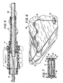
- FIG. 1 is a top perspective view of a portion of a swimming pool showing an operating pool cleaner having a power cable fitted with one embodiment of the invention;
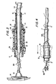
- FIG. 2 is a side elevation view, partial in section, illustrating one embodiment of the apparatus of the invention in relation to a coiled power cable;
- FIG. 3 is a side elevation view similar to Fig.2 in which the apparatus of the invention is shown in section;
- FIG. 4 is an further elevation view similar to that of Fig. 2, partly in phantom, showing the method of utilizing the apparatus of the invention to uncoil the power cable;
- FIG. 5 is a side elevation view similar to Fig. 4, partly in section;
- FIG. 6 is a perspective view simile to Fig. 1 showing the power cable in a relaxed, uncoiled condition following the practice of the method of the invention;
- FIG. 7 is a side elevation view of another embodiment of the apparatus of the invention, shown partly in section; and
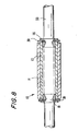
- FIG. 8 is a side elevation view of yet another embodiment of the apparatus of the invention, shown partly in section.
- With reference to Fig. 1, there is shown a self-propelled robotic
swimming pool cleaner 40 traversing the bottom surface ofswimming pool 60. Due to the repetitive turning movements of thecleaner 40, the attachedpower cable 50 has become coiled and twisted so that its effective length between the cleaner and the fixedexternal power supply 54 located adjacent the pool has been shortened. As illustrated in Fig. 1, but as more clearly shown in Fig. 2, theuncoiling apparatus 10 of the invention is affixed to thepower cable 50 proximate the plug or cable connector by which the power cable is joined to the outlet of thepower supply 54. In alternative embodiment, the uncoiling apparatus can be affixed to the opposite end of thepower cable 50 proximate a removable electrical connector (not shown) that allows the cable to be disconnected from theswimming pool cleaner 40. In yet another embodiment, where both ends of thepower cable 50 can be removed from attachment to the power supply and the pool cleaner, the uncoiling apparatus can be affixed adjacent to both of the free ends to further facilitate and expedite the removal of coils and untwisting of the power cable. It will also be understood that one or moreuncoiling assemblies 10 can be affixed at positions intermediate the ends of very long cables to facilitate the removal of twists and coils in intermediate sections, thereby reducing the forces that would have to be applied over the entire length of thepower cable 50. - With further reference to Fig. 2 and the cross-sectional view of Fig. 3, it will be seen that
uncoiling assembly 10 is comprised of aninterior surface 12 in the form of a an annular member formed with aflange 26 at its proximal end, i.e., the end that is proximate thecable connector 52 which becomes the free end of the power cable when removed from the power supply. As used herein, the proximal end of the apparatus is to be understood as that which is closest to the free end, or to an individual who is gripping the device to apply a pulling force, the distal end necessarily being that which is closest to the section of the power cable from which the twists and coils are to be removed. In this regard, reference is made to Fig. 4 in which there is shown in phantom ahand 55 griping thedevice 10 and applying a longitudinal or axial force in the direction of the arrow. - With further reference to Fig. 3, the
annular member 12 is formed with aflange 26 that defines abearing surface 28 at its proximal end.Annular member 12 is formed from or coated with a plastic material exhibiting low frictional characteristics on its exterior surface and is fixed in position onpower cable 50 byappropriate clamps 16. In the embodiment illustrated by Fig. 3, Heyco snap bushings are depicted. As will be understood by one of ordinary skill in the art, thecylindrical member 12 can be secured by any number of adhesive and/or other mechanical means which are well known in the art. A second surface in the form of coaxially mounted rotatableannular member 14 is positioned to surround all or a portion ofannular member 12.Member 14 is formed with a pair of radially extendingflanges 20 at its ends to facilitate manual gripping and prevent slipping. The exterior surface ofannular member 14 can be provided with an appropriately contoured surface to facilitate the user's grip and can be provided with a scored or otherwise roughened surface, or coated or covered with a high friction material to minimize slipping. In the embodiment illustrated schematically in Fig. 3, awasher 30 is placed onmember 12 and has an outside diameter that permits it to be received on the interior ofmember 14 and to be engaged by the interior surface ofcollar 21. From the embodiment illustrated by Fig. 3, it will be understood thatcap 22 is threaded ontomember 14 to form an integral construction. Alternatively, the entire unit can be formed integrally, as by molding or machining from an appropriate weather and chemically-resistant material, preferably a polymer that is designed to withstand weathering and swimming pool maintenance chemicals. Retaining means are also provided to maintain theouter member 14 in position around theinner member 12, such as by a radially projecting collar, flange orclip 17 located at the proximal end of the device. - The practice of the method and functioning of the
apparatus 10 will be described with reference to Fig. 5 where a longitudinal force has been applied manually by gripping the outercylindrical member 14 and pulling away from the twisted and coiled length of the power cord. This causes a relative movement betweencylindrical members washer 10 into contact with thebearing surface 28 offlange 26.Washer 30 is also constructed from an engineering plastic exhibiting a low coefficient of friction such as nylon, high or low density polyethylene, and copolymers, or other material that has been provided with a coating such as PTFE or FEP resins. The engagement ofwasher 30 withbearing surface 28 effectively creates a thrust bearing, and the continued application of a longitudinal force against the resisting force of the twisted power cable results in a translation into a rotational movement that has the effect of uncoiling and removing the twists frompower cable 50. Following the practice of the method of the invention, thecable connector 52 is again inserted inpower supply outlet 54 as shown in Fig. 6 and thebuoyant cable 50 is restored to a relaxed, uncoiled condition which permits it to easily follow the course of the moving pool cleaner, thereby assuring that the pool cleaner will be able to complete either its pre-programmed movements or a random pattern intended to cover the entire surface of the pool to be cleaned. - With reference to Fig. 7, a further embodiment of the invention is illustrated in which the exterior surface of the
power cable 50 is employed to support a pair of bearings 31 that are securely affixed to the cable, as by adhesive. Each of the bearings 31 are comprised of anouter race 32, aninner race 34 and a plurality ofball bearings 36. In this embodiment, theouter race 32 is fixed with respect tocylindrical grip member 14 andcable 50, being secured toinner race 34 is able to freely rotate axially by virtue of the movement afforded byball bearings 36. As shown,grip 14 is also provided with radially extending flanges at its opposite ends to facilitate the manual gripping and application of the longitudinal pulling force required to produce the rotational movement to untwist and uncoilpower cable 50. As will be understood by one of ordinary skill in the mechanical arts, a variety of bearing constructions can be substituted for the ball bearings of Fig. 7. Equivalent constructions would include roller and needle bearings, thrust bearings, bearings having slip surfaces without internal moving parts, and the like. The bearings can be of plastic or stainless steel construction. It is also to be understood that the bearings can be secured with respect to thepower cable 50 and/or the exteriorannular grip member 14 by means other than adhesive, for example, by specially molded channels and the like. - A further embodiment of the rotating grip assembly of the invention is illustrated in Fig. 8 in which inner
annular member 12 and outerannular member 14 are maintained in relative rotational engagement by a pair of washers 18 that extend radially fromsnap bushings 16 that engage thecable member 50 andannular member 12. As will be understood from the descriptions provided above, the application of a longitudinal or axial force to outerannular member 14 against one or the other of the bearing washers 18 which are fixed with respect tocable 50, will translate into a rotational force causing thecable 50 to untwist.
Claims (24)
- An apparatus (10) for removing undesired coils in a coiled swimming pool cleaner power cable (50) extending between power supply means and the pool cleaner (40), said power cable (50) having affixed a non-rotatable cable connector (52) on at least one end that can be disconnected from said power supply means (54) or said pool cleaner (40), the apparatus comprising:a) a first fixed surface (12) adapted to extend around and be affixed to the power cable (50) proximate the cable connector (52);b) a second surface (14) extending around, and rotatable in relation to the first surface (12); andc) bearing means (28; 31) that are fixed with respect to the power cable (50) when the first surface (12) is affixed to the cable and extend to contact said rotatable second surface (14) and to retain said second surface (14) in position with respect to the first surface (12) wherein the second surface (14) is adapted to receive an axial force in the direction of the disconnected cable connector (52) such that the axial force is translated by the bearing means into an uncoiling rotational movement of the power cable (50).
- The apparatus of claim 1 where the first surface is the exterior surface of the power cable (50).
- The apparatus of claim 1 or 2 where the bearing means (28; 31) is secured to the exterior surface of the power cable (50).
- The apparatus of any one of the preceeding claims where said second surface (14) is a rotatable annular member and the bearing means (31) comprise a pair of annular bearing members that contact the rotatable annular member in longitudinally spaced relation.
- The apparatus of claim 4 where the bearing members are roller bearings and the inner race (32) of each said bearings are fixed relative to the power cable (50).
- The apparatus of any one of the preceeding claims where the first (12) and second (14) surfaces are respectively, first (12) and second annular (24) members constructed of low-friction material and mounted coaxially on said power cable (50), and said bearing means (28) extends radially to contact the end of the second annular member proximate the cable connector (52).
- The apparatus of claim 6 where the bearing means (28) is integrally formed with the first annular member.
- The apparatus of any one of the preceeding claims which further comprises retaining means for maintaining the relative position of the first (12) and second (14) surfaces with respect to the power cable (50).
- The apparatus of any one of the preceeding claims where the bearing means (28) is a thrust bearing having a body that surrounds and is affixed to the power cable (50).
- The apparatus of any one of the preceeding claims where the second surface (14) comprises manual grip means.
- The apparatus of claim 10 where the manual grip means includes an irregular surface contour.
- The apparatus of claim 10 or 11 where the manual grip means includes a high friction coating.
- The apparatus of claim 10, 11 or 12 where the manual grip means includes at least one flange (20) extending radially outward at the end of the surface proximate the cable connector (52).
- The apparatus of any one of the preceeding claims where the first (12) and second (14) surfaces are comprised of first and second annular members co-axially mounted on said power cable (50).
- The apparatus of claim 14, where at least one of the annular members is formed from two sections that are joined along a longitudinal parting line.
- The apparatus of claim 15, where the two sections forming and annular member are joined mechanically.
- The apparatus of claim 15, where the two sections forming an annular member are joined adhesively.
- The apparatus of any one of the preceeding claims where an offset portion of the second surface extends radially towards the power cable (50) and terminates proximate the bearing means, whereby the offset portion contacts the bearing means when the axial force is applied to the second surface (14).
- The apparatus of claim 18 where the bearing means comprises a planar surface exhibiting a low coefficient of friction.
- A method for removing undesired coils in a coiled swimming pool cleaner power cable (50) extending between power supply means and the pool cleaner (40), said power cable (50) having affixed a non-rotable cable connector on at least one end that can be disconnected from said power supply means or said pool cleaner (40), the method comprising:a. providing a bearing-mounted manual grip member;b. securing the bearing-mounted manual grip member (14) to the power cable (50) proximate the cable connector (52) and in co-axial alignment with the power cable (50);c. disconnecting the cable connector (52) from either the power supply means of the pool cleaner (10);d. manually applying an axial force to the grip member in the direction of the free end of the cable connector (52) and against the resisting force of the coiled power cable (50), whereby the axial force is translated into a rotational movement of the power cable in a direction that removes coils from the power cable; ande. continuing to apply the axial force to the grip member (14) until the rotational movement of the powercable (50) ceases.
- The method of claim 20 where the bearing-mounted grip member (14) is secured directly to the exterior surface of the power cables (50).
- The method of claim 20 or 21 where the bearing-mounted grip member6 ' secured to the power cable by mechanical fasteners.
- The method of claim 20, 21 or 22 where the bearing-mounted grip member (1) comprises a thrust bearing. .
- The method of any one of claims 20 to 23 where the bearing-mounted grip member (14) comprises an annular member having a contoured gripping surface.
Applications Claiming Priority (2)
| Application Number | Priority Date | Filing Date | Title |
|---|---|---|---|
| US707763 | 2000-11-07 | ||
| US09/707,763 US6448494B1 (en) | 2000-11-07 | 2000-11-07 | Cable uncoiling device for robotic pool cleaner |
Publications (3)
| Publication Number | Publication Date |
|---|---|
| EP1207594A2 EP1207594A2 (en) | 2002-05-22 |
| EP1207594A3 EP1207594A3 (en) | 2003-09-03 |
| EP1207594B1 true EP1207594B1 (en) | 2006-08-30 |
Family
ID=24843077
Family Applications (1)
| Application Number | Title | Priority Date | Filing Date |
|---|---|---|---|
| EP01126418A Expired - Lifetime EP1207594B1 (en) | 2000-11-07 | 2001-11-07 | Cable uncoiling device for robotic pool cleaner |
Country Status (5)
| Country | Link |
|---|---|
| US (1) | US6448494B1 (en) |
| EP (1) | EP1207594B1 (en) |
| AT (1) | ATE338361T1 (en) |
| DE (1) | DE60122653T2 (en) |
| ES (1) | ES2270937T3 (en) |
Families Citing this family (15)
| Publication number | Priority date | Publication date | Assignee | Title |
|---|---|---|---|---|
| US7089876B2 (en) * | 2002-11-12 | 2006-08-15 | Aquatron Llc | Floating electronic platform for swimming pools and spas |
| US6875924B2 (en) * | 2003-09-09 | 2005-04-05 | Uniprise International, Inc. | Extendible flexible electrical conduit with conductors therein |
| US7621014B2 (en) * | 2006-09-29 | 2009-11-24 | Aquatron Llc | Method for controlling twisting of pool cleaner power cable |
| US20080099409A1 (en) * | 2006-10-26 | 2008-05-01 | Aquatron Robotic Systems Ltd. | Swimming pool robot |
| JP5887528B2 (en) * | 2011-08-11 | 2016-03-16 | パナソニックIpマネジメント株式会社 | Electric vehicle charging device |
| US20130087382A1 (en) * | 2011-10-06 | 2013-04-11 | Giora Erlich | Floating power cable with low-friction surface for swimming pool cleaners |
| US8366396B2 (en) * | 2011-11-28 | 2013-02-05 | General Electric Company | Unit for cable management and wind turbine |
| EP2669450B1 (en) * | 2012-05-30 | 2015-04-01 | Fabrizio Bernini | Apparatus for cleaning swimming pools |
| US9203199B2 (en) | 2013-03-15 | 2015-12-01 | Aqua Products, Inc. | Waterproof separable swivel connector |
| US9246290B1 (en) | 2014-07-14 | 2016-01-26 | Dongguan Smartpool Prodwcts Incorporated Co Ltd | Swivel cord-connector |
| US20160105010A1 (en) * | 2014-10-09 | 2016-04-14 | Southern Technical Control, LLC | Repairable Power Loop (Cord) Assembly |
| FR3027725B1 (en) | 2014-10-23 | 2018-02-02 | Zodiac Pool Care Europe | POWER CABLE FOR A SWIMMING POOL CLEANING ROBOT |
| USD785260S1 (en) * | 2015-04-14 | 2017-04-25 | Intex Marketing Ltd. | Pool cleaner |
| USD813478S1 (en) * | 2016-07-28 | 2018-03-20 | Water Technology Llc. | Hand-held submersible aquarium power cleaner |
| CN210239261U (en) | 2019-05-21 | 2020-04-03 | 明达实业(厦门)有限公司 | Wheel brush fixing structure of pool cleaner |
Citations (3)
| Publication number | Priority date | Publication date | Assignee | Title |
|---|---|---|---|---|
| US2253075A (en) * | 1940-11-26 | 1941-08-19 | Francis E Johnson | Toy |
| US4375886A (en) * | 1980-12-19 | 1983-03-08 | Strombecker Corporation | Jump rope |
| US4919417A (en) * | 1988-08-15 | 1990-04-24 | Poulas Peter W | Liquid filled jump rope |
Family Cites Families (11)
| Publication number | Priority date | Publication date | Assignee | Title |
|---|---|---|---|---|
| US2790152A (en) * | 1953-05-28 | 1957-04-23 | Mohr Karl | Swiveled cable connector |
| US4593899A (en) * | 1980-05-09 | 1986-06-10 | Miller Robert A | Exercise jumping rope |
| US4592605A (en) * | 1985-02-11 | 1986-06-03 | Kapler Albert W | Apparatus for preventing the twisting of an electrical cord or cable |
| DE3914840A1 (en) * | 1989-05-05 | 1990-11-08 | Vorwerk Co Interholding | TELESCOPICOUS GUIDE FOR FLOOR MAINTENANCE EQUIPMENT |
| US5337434A (en) * | 1993-04-12 | 1994-08-16 | Aqua Products, Inc. | Directional control means for robotic swimming pool cleaners |
| DE9318460U1 (en) * | 1993-12-02 | 1995-03-30 | Vorwerk & Co Interholding Gmbh, 42275 Wuppertal | Electric motor-operated vacuum cleaner with a telescopic handle |
| US5911381A (en) * | 1994-05-11 | 1999-06-15 | Plumettaz As | Stocking device for coilable elements and method of use |
| JP3634470B2 (en) * | 1995-11-09 | 2005-03-30 | 矢崎総業株式会社 | Relative rotating member relay device |
| US5973264A (en) * | 1996-08-07 | 1999-10-26 | North American Technologies Co., Inc. | Modular electrical service riser with retractable conduit |
| US6412133B1 (en) * | 1999-01-25 | 2002-07-02 | Aqua Products, Inc. | Water jet reversing propulsion and directional controls for automated swimming pool cleaners |
| US6310290B1 (en) * | 2001-04-12 | 2001-10-30 | Arlington Industries, Inc. | Cable connector |
-
2000
- 2000-11-07 US US09/707,763 patent/US6448494B1/en not_active Expired - Lifetime
-
2001
- 2001-11-07 EP EP01126418A patent/EP1207594B1/en not_active Expired - Lifetime
- 2001-11-07 DE DE60122653T patent/DE60122653T2/en not_active Expired - Lifetime
- 2001-11-07 ES ES01126418T patent/ES2270937T3/en not_active Expired - Lifetime
- 2001-11-07 AT AT01126418T patent/ATE338361T1/en not_active IP Right Cessation
Patent Citations (3)
| Publication number | Priority date | Publication date | Assignee | Title |
|---|---|---|---|---|
| US2253075A (en) * | 1940-11-26 | 1941-08-19 | Francis E Johnson | Toy |
| US4375886A (en) * | 1980-12-19 | 1983-03-08 | Strombecker Corporation | Jump rope |
| US4919417A (en) * | 1988-08-15 | 1990-04-24 | Poulas Peter W | Liquid filled jump rope |
Also Published As
| Publication number | Publication date |
|---|---|
| DE60122653T2 (en) | 2007-09-20 |
| ES2270937T3 (en) | 2007-04-16 |
| EP1207594A2 (en) | 2002-05-22 |
| ATE338361T1 (en) | 2006-09-15 |
| DE60122653D1 (en) | 2006-10-12 |
| US6448494B1 (en) | 2002-09-10 |
| EP1207594A3 (en) | 2003-09-03 |
Similar Documents
| Publication | Publication Date | Title |
|---|---|---|
| US6448494B1 (en) | Cable uncoiling device for robotic pool cleaner | |
| US4669145A (en) | Hose reel system | |
| US10987708B2 (en) | Drain cleaning systems using sheath protected flexible shaft | |
| US4356582A (en) | Pool sweep brush | |
| US5402551A (en) | Vacuum hose storage and access apparatus for a central vacuum cleaning system | |
| US4842108A (en) | Power retract electric cord reel | |
| US20040168299A1 (en) | Submersible pool cleaner with integral rechargeable battery | |
| US12496624B2 (en) | Torque limiter for powered drain cleaner | |
| US3999240A (en) | Cable cleaning device | |
| KR102149603B1 (en) | Auto cleaning device for make up brush | |
| CN116019401B (en) | Cleaning heads and hard surface cleaning equipment with cleaning heads | |
| CN218289944U (en) | Universal cable winding device | |
| FI70350B (en) | ANORDNING FOER UPPBEVARING AV ELKABLAR | |
| US20170059157A1 (en) | Device for cleaning and remotely inspecting a chimney | |
| JP4510731B2 (en) | Cleaning jig for piping | |
| CN214569731U (en) | Cable tidying and winding device for building construction | |
| CN114264600A (en) | Grinding detection device before installation of warm through pipe | |
| US5794648A (en) | Hose winding apparatus | |
| CN219058129U (en) | Power cable for solar power generation equipment | |
| US20080042433A1 (en) | Electrical swivel connector | |
| CN222683937U (en) | Electromechanical installation pipeline equipment | |
| KR20170123733A (en) | Apparatus for Cleaning of Pipe Improved Cleaning Power | |
| CN223234519U (en) | Belt cleaning device of electrified equipment | |
| KR102433803B1 (en) | Electric device of reel for fishing | |
| JPH0330383Y2 (en) |
Legal Events
| Date | Code | Title | Description |
|---|---|---|---|
| PUAI | Public reference made under article 153(3) epc to a published international application that has entered the european phase |
Free format text: ORIGINAL CODE: 0009012 |
|
| AX | Request for extension of the european patent |
Free format text: AL;LT;LV;MK;RO;SI |
|
| RIN1 | Information on inventor provided before grant (corrected) |
Inventor name: ERLICH, GIORIA Inventor name: CHILTON, SETH M. |
|
| PUAL | Search report despatched |
Free format text: ORIGINAL CODE: 0009013 |
|
| AK | Designated contracting states |
Kind code of ref document: A3 Designated state(s): AT BE CH CY DE DK ES FI FR GB GR IE IT LI LU MC NL PT SE TR |
|
| AX | Request for extension of the european patent |
Extension state: AL LT LV MK RO SI |
|
| 17P | Request for examination filed |
Effective date: 20031222 |
|
| 17Q | First examination report despatched |
Effective date: 20040223 |
|
| AKX | Designation fees paid |
Designated state(s): AT BE CH CY DE DK ES FI FR GB GR IE IT LI LU MC NL PT SE TR |
|
| GRAC | Information related to communication of intention to grant a patent modified |
Free format text: ORIGINAL CODE: EPIDOSCIGR1 |
|
| GRAP | Despatch of communication of intention to grant a patent |
Free format text: ORIGINAL CODE: EPIDOSNIGR1 |
|
| RIN1 | Information on inventor provided before grant (corrected) |
Inventor name: CHILTON, SETH M. Inventor name: ERLICH, GIORIA |
|
| GRAS | Grant fee paid |
Free format text: ORIGINAL CODE: EPIDOSNIGR3 |
|
| GRAA | (expected) grant |
Free format text: ORIGINAL CODE: 0009210 |
|
| AK | Designated contracting states |
Kind code of ref document: B1 Designated state(s): AT BE CH CY DE DK ES FI FR GB GR IE IT LI LU MC NL PT SE TR |
|
| PG25 | Lapsed in a contracting state [announced via postgrant information from national office to epo] |
Ref country code: IT Free format text: LAPSE BECAUSE OF FAILURE TO SUBMIT A TRANSLATION OF THE DESCRIPTION OR TO PAY THE FEE WITHIN THE PRESCRIBED TIME-LIMIT;WARNING: LAPSES OF ITALIAN PATENTS WITH EFFECTIVE DATE BEFORE 2007 MAY HAVE OCCURRED AT ANY TIME BEFORE 2007. THE CORRECT EFFECTIVE DATE MAY BE DIFFERENT FROM THE ONE RECORDED. Effective date: 20060830 Ref country code: BE Free format text: LAPSE BECAUSE OF FAILURE TO SUBMIT A TRANSLATION OF THE DESCRIPTION OR TO PAY THE FEE WITHIN THE PRESCRIBED TIME-LIMIT Effective date: 20060830 Ref country code: NL Free format text: LAPSE BECAUSE OF FAILURE TO SUBMIT A TRANSLATION OF THE DESCRIPTION OR TO PAY THE FEE WITHIN THE PRESCRIBED TIME-LIMIT Effective date: 20060830 Ref country code: CH Free format text: LAPSE BECAUSE OF FAILURE TO SUBMIT A TRANSLATION OF THE DESCRIPTION OR TO PAY THE FEE WITHIN THE PRESCRIBED TIME-LIMIT Effective date: 20060830 Ref country code: FI Free format text: LAPSE BECAUSE OF FAILURE TO SUBMIT A TRANSLATION OF THE DESCRIPTION OR TO PAY THE FEE WITHIN THE PRESCRIBED TIME-LIMIT Effective date: 20060830 Ref country code: AT Free format text: LAPSE BECAUSE OF FAILURE TO SUBMIT A TRANSLATION OF THE DESCRIPTION OR TO PAY THE FEE WITHIN THE PRESCRIBED TIME-LIMIT Effective date: 20060830 Ref country code: LI Free format text: LAPSE BECAUSE OF FAILURE TO SUBMIT A TRANSLATION OF THE DESCRIPTION OR TO PAY THE FEE WITHIN THE PRESCRIBED TIME-LIMIT Effective date: 20060830 |
|
| REG | Reference to a national code |
Ref country code: GB Ref legal event code: FG4D |
|
| REG | Reference to a national code |
Ref country code: CH Ref legal event code: EP |
|
| REG | Reference to a national code |
Ref country code: IE Ref legal event code: FG4D |
|
| REF | Corresponds to: |
Ref document number: 60122653 Country of ref document: DE Date of ref document: 20061012 Kind code of ref document: P |
|
| PG25 | Lapsed in a contracting state [announced via postgrant information from national office to epo] |
Ref country code: IE Free format text: LAPSE BECAUSE OF NON-PAYMENT OF DUE FEES Effective date: 20061107 |
|
| PG25 | Lapsed in a contracting state [announced via postgrant information from national office to epo] |
Ref country code: DK Free format text: LAPSE BECAUSE OF FAILURE TO SUBMIT A TRANSLATION OF THE DESCRIPTION OR TO PAY THE FEE WITHIN THE PRESCRIBED TIME-LIMIT Effective date: 20061130 Ref country code: SE Free format text: LAPSE BECAUSE OF FAILURE TO SUBMIT A TRANSLATION OF THE DESCRIPTION OR TO PAY THE FEE WITHIN THE PRESCRIBED TIME-LIMIT Effective date: 20061130 Ref country code: MC Free format text: LAPSE BECAUSE OF NON-PAYMENT OF DUE FEES Effective date: 20061130 |
|
| PG25 | Lapsed in a contracting state [announced via postgrant information from national office to epo] |
Ref country code: PT Free format text: LAPSE BECAUSE OF FAILURE TO SUBMIT A TRANSLATION OF THE DESCRIPTION OR TO PAY THE FEE WITHIN THE PRESCRIBED TIME-LIMIT Effective date: 20070212 |
|
| REG | Reference to a national code |
Ref country code: CH Ref legal event code: PL |
|
| NLV1 | Nl: lapsed or annulled due to failure to fulfill the requirements of art. 29p and 29m of the patents act | ||
| ET | Fr: translation filed | ||
| REG | Reference to a national code |
Ref country code: ES Ref legal event code: FG2A Ref document number: 2270937 Country of ref document: ES Kind code of ref document: T3 |
|
| PLBE | No opposition filed within time limit |
Free format text: ORIGINAL CODE: 0009261 |
|
| STAA | Information on the status of an ep patent application or granted ep patent |
Free format text: STATUS: NO OPPOSITION FILED WITHIN TIME LIMIT |
|
| GBPC | Gb: european patent ceased through non-payment of renewal fee |
Effective date: 20061130 |
|
| 26N | No opposition filed |
Effective date: 20070531 |
|
| PG25 | Lapsed in a contracting state [announced via postgrant information from national office to epo] |
Ref country code: GB Free format text: LAPSE BECAUSE OF NON-PAYMENT OF DUE FEES Effective date: 20061130 |
|
| PG25 | Lapsed in a contracting state [announced via postgrant information from national office to epo] |
Ref country code: GR Free format text: LAPSE BECAUSE OF FAILURE TO SUBMIT A TRANSLATION OF THE DESCRIPTION OR TO PAY THE FEE WITHIN THE PRESCRIBED TIME-LIMIT Effective date: 20061201 |
|
| PG25 | Lapsed in a contracting state [announced via postgrant information from national office to epo] |
Ref country code: LU Free format text: LAPSE BECAUSE OF NON-PAYMENT OF DUE FEES Effective date: 20061107 Ref country code: TR Free format text: LAPSE BECAUSE OF FAILURE TO SUBMIT A TRANSLATION OF THE DESCRIPTION OR TO PAY THE FEE WITHIN THE PRESCRIBED TIME-LIMIT Effective date: 20060830 |
|
| PG25 | Lapsed in a contracting state [announced via postgrant information from national office to epo] |
Ref country code: CY Free format text: LAPSE BECAUSE OF FAILURE TO SUBMIT A TRANSLATION OF THE DESCRIPTION OR TO PAY THE FEE WITHIN THE PRESCRIBED TIME-LIMIT Effective date: 20060830 |
|
| PGFP | Annual fee paid to national office [announced via postgrant information from national office to epo] |
Ref country code: DE Payment date: 20131127 Year of fee payment: 13 |
|
| REG | Reference to a national code |
Ref country code: DE Ref legal event code: R119 Ref document number: 60122653 Country of ref document: DE |
|
| PG25 | Lapsed in a contracting state [announced via postgrant information from national office to epo] |
Ref country code: DE Free format text: LAPSE BECAUSE OF NON-PAYMENT OF DUE FEES Effective date: 20150602 |
|
| REG | Reference to a national code |
Ref country code: FR Ref legal event code: PLFP Year of fee payment: 15 |
|
| REG | Reference to a national code |
Ref country code: FR Ref legal event code: PLFP Year of fee payment: 16 |
|
| REG | Reference to a national code |
Ref country code: FR Ref legal event code: PLFP Year of fee payment: 17 |
|
| REG | Reference to a national code |
Ref country code: ES Ref legal event code: PC2A Owner name: AQUATRON ROBOTIC TECHNOLOGY, LTD. Effective date: 20191120 |
|
| PGFP | Annual fee paid to national office [announced via postgrant information from national office to epo] |
Ref country code: IT Payment date: 20191125 Year of fee payment: 19 Ref country code: FR Payment date: 20191125 Year of fee payment: 19 Ref country code: ES Payment date: 20191202 Year of fee payment: 19 |
|
| PG25 | Lapsed in a contracting state [announced via postgrant information from national office to epo] |
Ref country code: IT Free format text: LAPSE BECAUSE OF NON-PAYMENT OF DUE FEES Effective date: 20201107 Ref country code: FR Free format text: LAPSE BECAUSE OF NON-PAYMENT OF DUE FEES Effective date: 20201130 |
|
| REG | Reference to a national code |
Ref country code: ES Ref legal event code: FD2A Effective date: 20220131 |
|
| PG25 | Lapsed in a contracting state [announced via postgrant information from national office to epo] |
Ref country code: ES Free format text: LAPSE BECAUSE OF NON-PAYMENT OF DUE FEES Effective date: 20201108 |