EP1207583A2 - Adaptive array antenna receiving apparatus - Google Patents
Adaptive array antenna receiving apparatus Download PDFInfo
- Publication number
- EP1207583A2 EP1207583A2 EP01127167A EP01127167A EP1207583A2 EP 1207583 A2 EP1207583 A2 EP 1207583A2 EP 01127167 A EP01127167 A EP 01127167A EP 01127167 A EP01127167 A EP 01127167A EP 1207583 A2 EP1207583 A2 EP 1207583A2
- Authority
- EP
- European Patent Office
- Prior art keywords
- signal
- predetermined number
- despreading
- signals
- supplied
- Prior art date
- Legal status (The legal status is an assumption and is not a legal conclusion. Google has not performed a legal analysis and makes no representation as to the accuracy of the status listed.)
- Withdrawn
Links
Images


Classifications
-
- H—ELECTRICITY
- H04—ELECTRIC COMMUNICATION TECHNIQUE
- H04B—TRANSMISSION
- H04B7/00—Radio transmission systems, i.e. using radiation field
- H04B7/02—Diversity systems; Multi-antenna system, i.e. transmission or reception using multiple antennas
- H04B7/04—Diversity systems; Multi-antenna system, i.e. transmission or reception using multiple antennas using two or more spaced independent antennas
- H04B7/08—Diversity systems; Multi-antenna system, i.e. transmission or reception using multiple antennas using two or more spaced independent antennas at the receiving station
-
- H—ELECTRICITY
- H01—ELECTRIC ELEMENTS
- H01Q—ANTENNAS, i.e. RADIO AERIALS
- H01Q3/00—Arrangements for changing or varying the orientation or the shape of the directional pattern of the waves radiated from an antenna or antenna system
- H01Q3/26—Arrangements for changing or varying the orientation or the shape of the directional pattern of the waves radiated from an antenna or antenna system varying the relative phase or relative amplitude of energisation between two or more active radiating elements; varying the distribution of energy across a radiating aperture
- H01Q3/2605—Array of radiating elements provided with a feedback control over the element weights, e.g. adaptive arrays
-
- H—ELECTRICITY
- H01—ELECTRIC ELEMENTS
- H01Q—ANTENNAS, i.e. RADIO AERIALS
- H01Q3/00—Arrangements for changing or varying the orientation or the shape of the directional pattern of the waves radiated from an antenna or antenna system
- H01Q3/26—Arrangements for changing or varying the orientation or the shape of the directional pattern of the waves radiated from an antenna or antenna system varying the relative phase or relative amplitude of energisation between two or more active radiating elements; varying the distribution of energy across a radiating aperture
- H01Q3/2682—Time delay steered arrays
Definitions
- This invention relates to an adaptive array antenna receiving apparatus and a method therefor and, in particular, to an adaptive array antenna receiving system in which a transmitted s ⁇ gnal of a CDMA system is received by a plurality of antenna elements forming an adaptive array antenna.
- a CDMA (Code Division Multiple Access) system attracts attention as a radio transmitting system capable of considerably increasing a subscriber capacity.
- a CDMA adaptive array antenna receiving apparatus used in the CDMA system is disclosed in Wang et al "Adaptive Array Antenna Combined with Tapped Delay Line Using Processing Gain for Direct-Sequence/Spread-Spectrum Multiple Access System” (IEICE Transactions, Vol. J75-BII, No. 11, pp. 815-825, 1992) and Tanaka et al "The Performance of Decision-Directed Coherent Adaptive Diversity in DS-CDMA Reverse Link” (IEICE, Technical Report on Radio Communication System, RCS-102, November 1996).
- an antenna weight is controlled by the use of a weighting control error signal derived after despreading.
- adaptive control is carried out so that an antenna directive pattern maximizing a received SIR (Signal to Interference Ratio) is formed to cancel an interference.
- the CDMA adaptive array antenna receiving apparatus comprises N receiving antennas 1-1 through 1-N forming an array antenna, (L - 1) delay units 2-2 through 2-L corresponding to the second through the L-th paths of the multipath except the first path of the multipath, respectively, (N x L) despreading circuits 3-1-1 through 3-L-N corresponding to the first through the L-th paths of the multipath and the N receiving antennas 1-1 through 1-N, L antenna weighting/combining circuits 4-1 through 4-L, and a MMSE (Minimum Mean Square Error) control circuit 5 connected ⁇ n common to the L antenna weighting/combining circuits 4-1 through 4-L, a reference signal producing circuit 7, an adder 6, and a subtractor 8.
- MMSE Minimum Mean Square Error
- the N receiving antennas 1-1 through 1-N are arranged in close proximity to one another so that a plurality of the received signals are mutually correlated.
- the delay units 2-2 through 2-L serve to delay the signals propagated through the second through the L-th paths of the multipath and received by the N receiving antennas 1-1 through 1-N.
- the received signals are classified into the first through the L-th multipath received signals due to delay times in the first through the L-th paths of the multipath.
- the second through the L-th multipath received signals are supplied to the delay units 2-2 through 2-L, respectively, while the first multipath received signals are directly supplied to the despreading circuits 3-1-1 through 3-1-N.
- the delay units 2-2 through 2-L delay the second through the L-th multipath received signals in synchronism with the timing on the first path of the multipath to produce second through L-th delayed signals. Therefore, a delay unit 2-1 corresponding to the first path of the multipath is omitted in Fig. 1 because no delay is required.
- the despreading circuits 3-1-1 through 3-1-N for the first path of the multipath are directly supplied with the signals received by the receiving antennas 1-1 through 1-N, respectively.
- the despreading circuits 3-2-1 through 3-2-N for the second path of the multipath are supplied with the second delayed signals produced by the delay unit 2-2.
- the despreading circuits 3-L-1 through 3-L-N for the L-th -path of the multipath are supplied with the L-th delayed signals produced by the delay unit 2-L.
- the despreading circuits 3-1-1 through 3-L-N produce despread signals.
- the despreading circuits 3-1-1 through 3-L-N send the despread signals to the antenna weighting/combining circuits 4-1 through 4-L and to the MMSE control circuit 5.
- the antenna weighting/combining circuits 4-1 through 4-L produce weighted and combined signals.
- the adder 6 sums the outputs of the antenna weighting/combining circuits 4-1 through 4-L to produce a sum signal as a rake combined signal and supplies the rake combined signal to the subtractor 8.
- the antenna weighting/combining circuit 4-1 comprises a plurality of multipliers 9-1 through 9-N and an adder 10.
- the antenna weighting/combining circuit 4-1 is supplied with the despread signals despread by the despreading circuits 3-1-1 through 3-1-N. Supplied with the despread signals and antenna weights produced by the MMSE control circuit 5, the multipliers 9-1 through 9-N multiply the despread signals by the antenna weights to produce weighted signals.
- the adder 10 sums the weighted signals to produce the sum of the weighted signals as an antenna combined signal and supplies the antenna combined signal to the adder 6 in Fig. 1.
- the antenna weighting/combining circuits 4-1 through 4-L form the directive pattern of the array antenna so that a desired signal component is given a gain and interference signal components are suppressed.
- the adder 6 sums the output signals of the antenna weighting/combining circuits 4-1 through 4-L to produce the rake combined signal.
- rake combination is carried out Supplied with the rake combined signal produced by the adder 6 and a reference signal produced by the reference signal producing circuit 7, the subtractor 8 subtracts the rake combined signal from the reference signal to obtain a common error signal.
- the subtractor 8 supplies the common error signal to the MMSE control circuit 5.
- the MMSE control circuit 5 controls the antenna weights so that a mean square of the common error signal is minimized.
- the MMSE control circuit 5 controls or updates the antenna weights by the use of an adaptive update algorithm.
- an adaptive update algorithm for example, an RLS (Recursive Least Square) algorithm can be used as the adaptive update algorithm.
- the despread signals y k,l,n (m) are supplied to the antenna weighting/combining circuits 4-1 through 4-L.
- the multipliers 9-1 through 9-N in the antenna weighting/combining circuits 4-1 through 4-L multiply the despread signals y k,l,n (m) by the antenna weights produced by the MMSE control circuit 5 to produce the weighted signals.
- the weighted signals are combined by the adder 10.
- the adder 10 produces the output signal as the antenna combined signal.
- the antenna weight for the n-th receiving antenna be represented by w k,l,n (m). Then, the antenna combined signal z k,l (m) for the l-th path of the multipath and for the k-th user is given by: where * represents a complex conjugate.
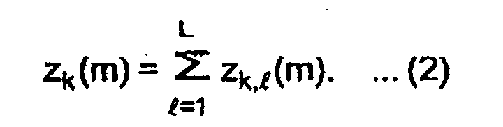
- the adder 6 in Fig. 1 adds the antenna combined signals produced by the antenna weighting/combining circuits 4-1 through 4-L so that the rake combination is carried out.
- the rake combined signal z k (m) for the k-th user is given by:
- the rake combined signal z k (m) is supplied to the subtractor 8.
- the MMSE control circuit 5 controls the antenna weights so that a square sum of exponential weight errors is directly minimized.
- the square sum Q (m) is represented by:
- ⁇ represents a weighting factor (0 ⁇ ⁇ ⁇ 1)
- e k (m) represents the common error signal produced by the subtractor 8.
- the common error signal is obtained by subtracting the rake combined signal produced by the adder 6 from the reference signal produced by the reference signal producing circuit 7.
- the subtractor 8 delivers the common error signal to the MMSE control circuit 6.
- a correlation matrix R xxk is calculated by a time average of exponential weights according to Equation (3):
- ⁇ represents a positive constant
- H a complex conjugate transpose
- U a unit matrix
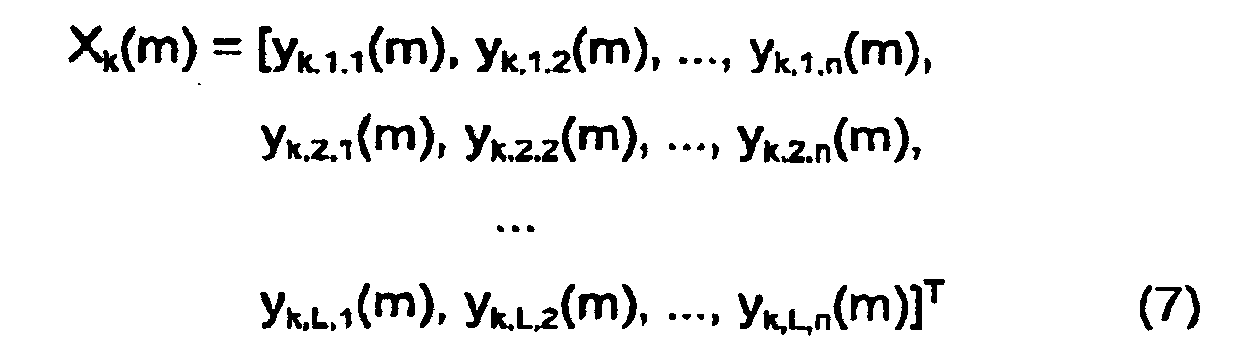
- X k (m) represents a despread signal vector of the despread signal produced by each of the despreading circuits 3-1-1 through 3-L-N and is defined by:
- T represents the transpose.
- the MMSE control circuit 5 updates the antenna weights by the use of the common error signal e k (m) produced by the subtractor 8 and the despread signals produced by the despreading circuits 3-1-1 through 3-L-N.
- the antenna weights are adaptively controlled by a MMSE criterion so that the common error signal e k (m) is minimized.
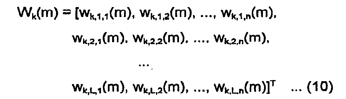
- W k (m) represents an antenna weight vector of the antenna weight produced by the MMSE control circuit 5 and is defined by:
- Equations (8) and (9) require the calculation of an inverse matrix R xxk -1 of the correlation matrix R xxk .
- the MMSE control circuit 5 requires a large amount of calculation according to the adaptive update algorithm. Such a large amount of calculation imposes a large processing load upon a digital signal processor (DSP). This is because, since the common error signal is used, the adaptive update algorithm for controlling the antenna weights so as to minimize the mean square of the common error signal requires calculation of an (N x L)- order correlation matrix R xxk .
- Adaptive array antennas receiving apparatuses according to this invention and receiving methods according to this invention are as follows:
- the adaptive update algorithm for calculating the antenna weighting factors by the use of an N-order correlation matrix independently for the respective fingers is equivalent to the adaptive update algorithm for calculating an (N x L)-order correlation matrix. Therefore, the antenna weighting factors are controlled by the use of the adaptive update algorithm independently for the respective fingers so as to minimize the mean square of the common error signal after rake combination. In this manner, the amount of calculation in the adaptive update algorithm used in all MMSE control circuits is considerably reduced proportionally from (NL) 2 to N 2 L. As a consequence, the processing load upon the DSP can be decreased.
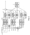
- a CDMA adaptive array antenna receiving apparatus according to the first embodiment of this invention in case where a common error signal is used. It is assumed here that the number of receiving antennas is equal to N (N being an integer not smaller than 2) and that the number of the paths of the multipath is equal to L (L being an integer not smaller than 1). Consideration will be made about the k-th user (k being an integer greater than 1).
- a CDMA adaptive array antenna receiving apparatus comprises N receiving antennas 1-1 through 1-N forming an array antenna, (L - 1) delay units 2-2 through 2-L corresponding to the second through the L-th paths of a multipath except the first path of the multipath, respectively, (N x L) despreading circuits 3-1-1 through 3-L-N corresponding to the first through the L-th paths of the multipath and the N receiving antennas 1-1 through 1-N, L antenna weighting/combining circuits 4-1 through 4-L, and L MMSE control circuits 5-1 through 5-L connected to the first through the L-th antenna weighting/combining circuits 4-1 through 4-L. respectively, a reference signal producing circuit 7, an adder 6, and a substractor 8.
- the signals are received by the receiving antennas 1-1 through 1-N and classified into the first through the L-th multipath received signals due to delay times in the first through the L-th paths of the multipath.
- the second through the L-th multipath received signals are supplied to the delay units 2-2 through 2-L, respectively, while the first multipath received signals are directly supplied to the despreading circuits 3-1-1 through 3-1-N.
- the delay units 2-2 through 2-L delay the second through the L-th multipath received signals to produce the second through the L-th delayed signals.
- the despreading circuits 3-1-1 through 3-L-N despread the first multipath received signals and the second through the L-th delayed signals to produce despread signals.
- the despreading circuits 3-1-1 through 3-L-N deliver the despread signals to the antenna weighting/combining circuit 4-1 through 4-L and to the MMSE control c ⁇ rcuits 5-1 through 5-L.
- the antenna weighting/combining circuits 4-1 through 4-L Supplied with the despread signals, the antenna weighting/combining circuits 4-1 through 4-L produce weighted and combined signals as antenna combined signals and supplies the antenna combined signals to the adder 6.
- the adder 6 sums the antenna combined signals to produce a sum signal as a rake combined signal and supplies the rake combined signal to the subtractor 8.
- each of the antenna weighting/combining circuits 4-1 through 4-L comprises a plurality of multipliers 9-1 through 9-N and an adder 10.
- the antenna weighting/combining circuits 4-1 through 4-L are supplied with the despread signals from the despreading circuits 3-1-1 through 3-L-N.
- the multipliers 9-1 through 9-N in each of the antenna weighting/combining circuits 4-1 through 4-L multiply the despread signals by antenna weights produced by each corresponding one of the MMSE control circuits 5-1 through 5-L to produce weighted signals.
- the adder 10 sums the weighted signals to produce the antenna combined signal.
- the antenna combined signal is delivered to the adder 6 in Fig. 3.
- the adder 6 sums the antenna combined signals produced by the antenna weighting/combining circuits 4-1 through 4-L to produce the rake combined signal.
- rake combination is carried out.
- the subtractor 8 Supplied with the rake combined signal produced by the adder 6 and a reference signal produced by the reference signal producing circuit 7, the subtractor 8 subtracts the rake combined signal from the reference signal to obtain a common error signal.
- the subtractor 8 supplies the common error signal to the MMSE control circuits 5-1 through 5-L.
- the MMSE control circuits 5-1 through 5-L control the antenna weights so that a mean square of the common error signal is minimized.
- the MMSE control circuits 5-1 through 5-L control or update the antenna weights by the use of an adaptive update algorithm.
- an RLS (Recursive Least Square) algorithm as a high-speed algorithm is preferably used.
- the algorithm for controlling the antenna weights using an N-order correlation matrix independently for the respective fingers contributes to considerable reduction in amount of calculation and in processing load upon a DSP.
- the receiving antennas 1-1 through 1-N receive the received signals each of which includes a desired signal component and a plurality of interference signal components multiplexed therewith.
- the receiving antennas 1-1 through 1-N are arranged in close proximity to one another so that the received signals are mutually correlated.
- the delay units 2-2 through 2-L serve to delay the received s ⁇ gnals propagated through the second through the L-th paths and received by the receiving antennas 1-1 through 1-N.
- the received signals are classified into the first through the L-th multipath received signals with reference to delay times in the first through the L-th paths of the multipath.
- the second through the L-th multipath received signals are supplied to the delay units 2-2 through 2-L, respectively, while the first multipath received signals are directly supplied to the despreading circuits 3-1-1 through 3-1-N.
- the delay units 2-2 through 2-L delay the second through the L-th multipath received signals in synchronism with the timing on the first path of the multipath to produce second through L-th delayed signals. Therefore, a delay unit 2-1 corresponding to the first path of the multipath is omitted in Fig. 3 because no delay is required.
- the despreading circuits 3-1-1 through 3-1-N for the first path of the multipath are directly supplied with the first multipath received signals received by the receiving antennas 1-1 through 1-N, respectively.
- the despreading circuits 3-2-1 through 3-2-N for the second path of the multipath are supplied with the second delayed signals produced by the delay unit 2-2.
- the despreading circuits 3-L-1 through 3-L-N for the L-th paths of the multipath are supplied with the L-th delayed signals produced by the delay unit 2-L.
- the timing in a particular path of the multipath is used in common by all of the receiving antennas 1-1 through 1-N. This is because the receiving antennas 1-1 through 1-N are arranged in close proximity to one another so that the received signals are mutually correlated and, therefore, the receiving antennas 1-1 through 1-N are assumed to have the same delay profile.
- the despreading circuits 3-1-1 through 3-L-N produce the despread signals.
- the despreading circuits 3-1-1 through 3-L-N send the despread signals to the antenna weighting/combining circuits 4-1 through 4-L and to the MMSE control circuits 5-1 through 5-L.
- the antenna weighting/combining circuits 4-1 through 4-L produce weighted and combined signals as the antenna combined signals and deliver the antenna combined signals to the adder 6.
- the adder 6 sums the weighted and combined outputs to produce a sum signal as a rake combined signal and supplies the rake combined signal to the subtractor 8.
- the antenna weighting/combining circuit 4-1 comprises the multipliers 9-1 through 9 N and the adder 10.
- the antenna weighting/combining circuit 4-1 is supplied with the despread signals despread by the despreading circuits 3-1-1 through 3-1-N. Supplied with the despread signals and antenna weights produced by the MMSE control circuit 5-1, the multipliers 9-1 through 9-N multiply the despread signals by the antenna weights to produce the weighted signals.
- the adder 10 sums the weighted signals to produce the antenna combined signal and supplies the antenna combined signal to the adder 6 in Fig. 3.
- the antenna weighting/combining circuits 4-1 through 4-L form the directive pattern of the array antenna so that the desired signal component is given a gain and the interference signal components are suppressed.
- the adder 6 sums the antenna combined s ⁇ gnals produced by the antenna weighting/combining circuits 4-1 through 4-L.
- rake combination is carried out. Supplied with the rake combined signal produced by the adder 6 and the reference signal produced by the reference signal producing circuit 7, the subtractor 8 subtracts the rake combined signal from the reference signal to obtain the common error signal.
- the subtractor 8 supplies the common error signal to the MMSE control circuits 5-1 through 5-L.
- the MMSE control circuits 5-1 through 5-L control the antenna weights so that the mean square of the common error signal is minimized.
- the MMSE control circuits 5-1 through 5-L control or update the antenna weights by the use of the adaptive update algorithm.
- the RLS algorithm as a high-speed algorithm is preferably used.
- the algorithm for controlling the antenna weights using an N-order correlation matrix independently for the respective fingers is used.
- ⁇ represents a positive constant
- H a complex conjugate transpose
- ⁇ a weighting factor (0 ⁇ ⁇ ⁇ 1).
- weighting factor ⁇ is great, the accuracy and the stability of adaptive control are excellent but the convergence of adaptive control is slow. On the other hand, if the weighting factor ⁇ is small, the convergence of adaptive control is fast but the accuracy and the stability of adaptive control are deteriorated.
- the weighting factor ⁇ In the RLS algorithm used in each of the MMSE control circuits 5-1 through 5-L, the weighting factor ⁇ must adapt ⁇ vely be varied depending upon a fading frequency so that the instantaneous channel fluctuation is followed by the antenna weights. Specifically, if the fading frequency is small, the weighting factor ⁇ is increased. If the fading frequency is large, the weighting factor ⁇ is decreased.
- the common error signal is obtained by subtracting the rake combined signal produced by the adder 6 from the reference signal produced by the reference signal producing circuit 7.
- the antenna weights are adaptively controlled by a MMSE criterion so that the common error signal e k (m) is minimized.
- Equat ⁇ ons (16) and (17) require the calculation of an inverse matrix of the correlation matrix R xxk,l .
- Equations (13) and (14) are transformed into the inverse matrix by the use of a matrix formula.
- Equations (19) and (20) instead of Equations (13) and (14), it is possible to obtain R xxk,l -1 without an enormous amount of calculation of the inverse matrix. Thus, it is possible to reduce the amount of calculation required to calculate the antenna weights.
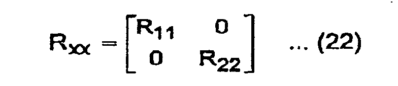
- the RLS algorithm for calculating the antenna weights by the use of the N-order correlation matrix independently for the respective fingers is equivalent to the RLS algorithm for calculating an (N x L)-order correlation matrix.
- the RLS algorithm used in the MMSE control circuits 5-1 through 5-L in the CDMA adaptive array antenna receiving apparatus according to this invention is equivalent to the RLS algorithm used in the single MMSE control circuit 5 in the related CDMA adaptive array antenna receiving apparatus.
- the correlation matrix R xx in case where the common error signal is used for all fingers is represented by a division matrix as follows:
- R 11 represents an autocorrelation matrix of the finger 1, R 22 , an autocorrelation matrix of the finger 2, R 12 , a cross-correlation matrix of the finger 1 to the finger 2, and R 21 , a cross-correlation matrix of the finger 2 to the finger 1.
- W(m) represents the weight vector for the finger 1 and the finger 2 at the m-th symbol
- W 1 (m) the weight vector for the finger 1 at the m-th symbol
- W 2 (m) the weight vector for the finger 2 at the m-th symbol
- X(m) represents the despread signal vector for the finger 1 and the finger 2 at the m-th symbol
- X 1 (m) the despread signal vector for the finger 1 at the m-th symbol.
- X 2 (m) the despread signal vector for the finger 2 at the m-th symbol, e
- the above equation is represented by the division matrix as follows: The above equation shows that, if no correlation exists between the respective fingers, the RLS algorithm of calculating the (N x L)-order correlation matrix is equivalent to the RLS algorithm of calculating the N-order correlation matrix independently for the respective fingers.
- W represents the weight vector for the finger 1 and finger 2
- W 1 represents the weight vector for the finger 1
- W 2 represents the weight vector for the finger 2
- S represents the correlation vector for the finger 1 and finger 2
- S 1 represents the correlation vector for the finger 1
- S 2 represents the correlation vector for the finger 2.
- N x L-order correlation matrix can be decreased in order number to N-order correlation matrices, L in number.
- the amount of calculation can be considerably reduced proportionally from (NL) 2 to N 2 L. It is therefore possible to reduce the processing load upon the DSP.
- a CDMA adaptive array antenna receiving apparatus is basically similar in structure to that of the first embodiment. Similar parts are designated by like reference numerals.
- the receiving apparatus further comprises a deciding unit 11 for making a decision upon symbol data of the rake combined signal produced by the adder 6 and for producing a decision output signal and a switch 12 connected to the decision output signal and the reference signal of the reference signal producing circuit 7.
- the deciding unit 11 is supplied with the rake combined signal from the adder 6 and makes the decision upon the symbol data.
- the common error signal is calculated by the use of not only the reference signal produced by the reference signal producing circuit 7 but also the decision output signal produced by the deciding unit 11. It is therefore possible to more quickly converge the antenna weights calculated in the MMSE control circuits 5-1 through 5-L according to the adaptive update algorithm.
- known pilot signals among the received signals are received as data signals.
- the pilot signals for the respective fingers are rake-combined to produce the rake combined signal.
- the rake combined signal is compared with the reference signal to produce the common error signal so that the antenna weights are controlled.
- the embodiment illustrated in Fig. 5 is applicable also to reception of other data signals than the p ⁇ lot signals.
- the switch 12 selects the reference signal from the reference signal producing circuit 7.
- the switch 12 selects the decision output signal from the deciding unit 11 to be used instead of the reference signal.
- This embodiment is the new advantage in that the antenna weights calculated in the MMSE control circuits 5-1 through 5-L according to the adaptive update algorithm can be more quickly converged.
- an SMI Sample Matrix Inversion
- the use of the SMI algorithm exhibits the similar effect, i.e., considerable reduction in amount of calculation and in processing load upon the DSP.
- a CDMA adaptive array antenna receiving apparatus according to the third embodiment of this invention will be described.
- the SMI algorithm is used as the adaptive update algorithm used in the MMSE control circuits 5-1 through 5-L. Similar parts are designated by like reference numerals.
- the subtractor 8 (Fig. 3) for calculating the common error signal by subtracting the rake combined signal produced by the adder 6 from the reference signal produced by the reference signal producing circuit 7 is omitted.
- the MMSE control circuits 5-1 through 5-L are supplied with the reference signal produced by the reference signal producing circuit 7.
- the MMSE control circuits 5-1 through 5-L control the antenna weights.
- Equation (35) requires the calculation of the inverse matrix of the correlation matrix R xxk,l . Therefore, in order to reduce the amount of calculation of the inverse matrix, the both sides of Equation (32) are transformed into the inverse matrix by the use of the matrix formula.
- Equation (36) instead of Equation (32), it is possible to obtain R xxk,l without an enormous amount of calculation of the inverse matrix. Thus, it is possible to reduce the amount of calculation required to calculate the antenna weights.
- the antenna weighting factors are controlled by the use of the adaptive update algorithm independently for the respective fingers so as to minimize the mean square of the common error signal after rake combination.
- the amount of calculation in the adaptive update algorithm used in all MMSE control circuits is considerably reduced proportionally from (NL) 2 to N 2 L. As a consequence, the processing load upon the DSP can be decreased.
Landscapes
- Engineering & Computer Science (AREA)
- Computer Networks & Wireless Communication (AREA)
- Signal Processing (AREA)
- Radio Transmission System (AREA)
- Variable-Direction Aerials And Aerial Arrays (AREA)
- Mobile Radio Communication Systems (AREA)
Abstract
Description






Claims (20)
- An adaptive array antenna receiving apparatus which receives a CDMA transmitted signal by a plurality of antenna elements (1-1 to 1-N) forming an adaptive array antenna and which includes a predetermined number L of fingers, where L is an integer greater than one, said receiving apparatus comprising:a predetermined number L of despreading means (3-1-1 to 3-L-N) forming said predetermíned number of fingers, each of said predetermined number of despreading means being supplied with received signals from said antenna elements for despreading the received signals to produce despread signals;a predetermined number L of weighting factor multiplying means (4-1 to 4-L) supplied with the despread signals from said predetermined number of despreading means, respectively, each of said predetermined number of weighting factor multiplying means being for multiplying the despread signals by weighting factors to produce a weighted signal;combining means (6) supplied with the weighted signals from said predetermined number of weighting factor multiplying means for combining the weighted signals to produce a rake combined signal;error signal producing means (8) supplied with the rake combined signal and a reference signal for calculating a difference between the rake combined signal and the reference signal to produce a common error signal representative of the difference; anda predetermined number L of control means (5-1 through 5-L) supplied with the despread signals from said predetermined number of despreading means, respectively, and with the common error signal in common and connected to said predetermined number of weighting factor multiplying means, each of said predetermined number of control means being for controlling the weighting factors for each of said predetermined number of weighting factor multiplying means so that a mean square of the common error signal is minimized.
- An adaptive array antenna receiving apparatus as claimed in claim 1, wherein each of said predetermined number of control means uses an RLS (Recursive Least Square) algorithm as an adaptive update algorithm for controlling the weighting factors for each of said predetermined number of weighting factor multiplying means.
- An adaptive array antenna receiving apparatus as claimed in claim 1 or 2, wherein said reference signal is a signal equivalent to a known pilot signal in case where each of the received signals is the known pilot signal.
- An adaptive array antenna receiving apparatus as claimed in claim 3, further comprising deciding means (11) for making a data decision upon the rake combined signal produced by said rake combining means to produce a decision output signal and switching means (12) for selectively switching the decision output signal produced by said deciding means and the reference signal, said switching means being controlled so that, when the received signal is the pilot signal and when the received signal is a data signal other than the pilot signal, the reference signal and the decision output signal are selected, respectively, to be supplied to said error signal producing means.
- An adaptive array antenna receiving apparatus as claimed in one of claims 1 to 4, wherein each of said predetermined number of control means controls the weighting factors for each of said predetermined number of weighting factor multiplying means by the use of an N-order (N being an integer not smaller than 2) correlation matrix in case where said antenna elements are N in number.
- An adaptive array antenna receiving apparatus as claimed in one of claims 1 to 5, wherein said predetermined number of despreading means which form said predetermined number of fingers correspond to a predetermined number L of paths of a multipath of the received signal from each of said antenna elements, said receiving apparatus further comprising delay means for delaying the received signal from each of said antenna elements by delay times corresponding to the paths of said multipath, respectively, to produce delayed signals which are supplied to corresponding ones of said predetermined number of despreading means, said corresponding ones of the predetermined number of despreading means corresponding to the paths of said multipath.
- An adaptive array antenna receiving apparatus which receives a CDMA transmitted signal by a plurality of antenna elements (1-1 to 1-N) forming an adaptive array antenna and which includes a predetermined number L of fingers, where L is an integer greater than one, said receiving apparatus comprising:a predetermined number L of despreading means (3-1-1 to 3-L-N) forming said predetermined number of fingers, each of said predetermined number of despreading means being supplied with received signals from said antenna elements for despreading the received signals to produce despread signals;a predetermined number L of weighting factor multiplying means (4-1 to 4-L) supplied with the despread signals from said predetermined number of despreading means, respectively, each of said predetermined number of weighting factor multiplying means being for multiplying the despread signals by weighting factors to produce a weighted signal;combining means (6) supplied with the weighted signals from said predetermined number of weighting factor multiplying means for combining the weighted signals:a predetermined number L of control means (5-1 through 5-L) supplied with the despread signals from said predetermined number of despreading means, respectively, and connected to said predetermined number of weighting factor multiplying means, each of said predetermined number of control means being for controlling the weighting factors for each of said predetermined number of weighting factor multiplying means.
- An adaptive array antenna receiving apparatus as claimed in claim 7, wherein each of said predetermined number L of control means uses an SMI (Sample Matrix Inversion) algorithm as an adaptive update algorithm for controlling the weighting factors.
- An adaptive array antenna receiving apparatus as claimed in claim 7 or 8, wherein each of said predetermined number of control means controls the weighting factors for each of said predetermined number of weighting factor multiplying means by the use of an N-order (N being an Integer not smaller than 2) correlation matrix in case where said antenna elements are N in number.
- An adaptive array antenna receiving apparatus as claimed in one of claims 7 to 9, wherein said predetermined number of despreading means forming said predetermined number of fingers correspond to a predetermined number L of paths of a multipath of the received signal from each of said antenna elements, said receiving apparatus further comprising delay means for delaying the received signal from each of said antenna elements by delay times corresponding to the paths of said multipath, respectively, to produce delayed signals which are supplied to corresponding ones of said predetermined number of despreading means, said corresponding ones of the predetermined number of despreading means corresponding to the paths of said multipath.
- A receiving method for use in an adaptive array antenna receiving apparatus which receives a CDMA transmitted signal by a plurality of antenna elements (1-1 to 1-N) forming an adaptive array antenna and which includes first through L-th fingers, where L is an integer greater than one, said receiving method comprising:first through L-th despreading steps (3-1-1 to 3-L-N) carried out in said first through said L-th fingers, each of said first through said L-th despreading steps being supplied with received signals from said antenna elements for despreading the received signals to produce despread signals;first through L-th weighting factor multiplying steps (4-1 to 4-L) supplied with the despread signals from said first through said L-th despreading steps, respectively, each of said first through said L-th weighting factor multiplying steps being for multiplying the despread signals by weighting factors to produce a weighted signal;a combining step (6) supplied with the weighted signals from said first through said L-th weighting factor multiplying steps for combining the weighted signals to produce a rake combined signal;an error signal producing step (8) supped with the rake combined signal and a reference signal for calculating a difference between the rake combined signal and the reference signal to produce a common error signal representative of the difference; andfirst through L-th control steps (5-1 through 5-L) supplied with the despread signals from said first through said L-th despreading steps, respectively, and with the common error signal in common, each of said first through said L-th control steps being for controlling the weighting factors for each of said first through said L-th weighting factor multiplying steps so that a mean square of the common error signal is minimized.
- A receiving method as claimed in claim 11, wherein each of said first through said L-th control steps uses an RLS (Recursive Least Square) algorithm as an adaptive update algorithm for controlling the weighting factors for each of said first through said L-th weighting factor multiplying steps.
- A receiving method as claimed in claim 11 or 12, wherein said reference signal is a signal equivalent to a known pilot signal in case where each of the received signals is the known pilot signal.
- A receiving method as claimed in claim 13, further comprising a deciding step (11) for making a data decision upon the rake combined signal produced by said rake combining step to produce a decision output signal and a switching step (12) for selectively switching the decision output signal produced by said deciding step and the reference signal, said switching step being controlled so that, when the received signal is the pilot signal and when the received signal is a data signal other than the pilot signal, the reference signal and the decision output signal are selected, respectively, to be supplied to said error signal producing step.
- A receiving method as claimed in one of claims 11 to 14, wherein each of said first through said L-th control steps controls the weighting factors for each of said first through said L-th weighting factor multiplying steps by the use of an N-order (N being an integer not smaller than 2) correlation matrix in case where said antenna elements are N in number.
- A receiving method as claimed in one of claims 11 to 15, wherein said first through said L-th fingers which carry out said first through said L-th despreading steps correspond to first through L-th paths of a multipath of the received signal from each of said antenna elements, said receiving method further comprising a delay step for delaying the received signal from each of said antenna elements by delay times corresponding to the paths of said multipath, respectively, to produce delayed signals which are supplied to corresponding ones of said first through said L-th despreading steps, said corresponding ones of the first through the L-th despreading steps corresponding to said first through said L-th paths of said multipath.
- A receiving method for use in an adaptive array antenna receiving apparatus which receives a CDMA transmitted signal by a plurality of antenna elements (1-1 to 1-N) forming an adaptive array antenna and which includes first through L-th fingers, where L is an integer greater than one, said receiving method comprising:first through L-th despreading steps (3-1-1 to 3-L-N) carried out in said first through said L-th fingers, each of said first through said L-th despreading steps being supplied with received signals from said antenna elements for despreading the received signals to produce despread signals;first through L-th weighting factor multiplying steps (4-1 to 4-L) supplied with the despread signals from said first through said L-th despreading steps, respectively, each of said first through said L-th weíghting factor multiplying steps being for multiplying the despread signals by weighting factors to produce a weighted signal;a combining step (6) supplied with the weighted signals from said first through said L-th weighting factor multiplying means for combining the weighted signals;first through L-th control steps (5-1 through 5-L) supplied with the despread signals from said first through said L-th despreading steps, respectively, each of said first through said L-th control steps being for controlling the weighting factors for each of said first through said L-th weighting factor multiplying steps.
- A receiving method as claimed in claim 17, wherein each of said first through said L-th control steps uses an SMI (Sample Matrix Inversion) algorithm as an adaptive update algorithm for controlling the weighting factors.
- A receiving method as claimed in claim 17, wherein each of said first through said L-th control steps controls the weighting factors for each of said first through said L-th weighting factor multiplying steps by the use of an N-order (N being an integer not smaller than 2) correlation matrix in case where said antenna elements are N in number.
- A receiving method as claimed in claim 17, 18 or 19, wherein said first through said L-th fingers which carries out said first through said L-th despreading steps correspond to first through L-th paths of a multipath of the received signal from each of said antenna elements, said receiving method further comprising a delay step for delaying the received signal from each of said antenna elements by delay times corresponding to the paths of said multipath, respectively, to produce delayed signals which are supplied to corresponding ones of said first through said L-th despreading steps, said corresponding ones of the first through the L-th despreading steps corresponding to said first through said L-th paths of said multipath.
Applications Claiming Priority (2)
| Application Number | Priority Date | Filing Date | Title |
|---|---|---|---|
| JP2000347388 | 2000-11-15 | ||
| JP2000347388A JP2002151937A (en) | 2000-11-15 | 2000-11-15 | Adaptive array antenna receiver |
Publications (2)
| Publication Number | Publication Date |
|---|---|
| EP1207583A2 true EP1207583A2 (en) | 2002-05-22 |
| EP1207583A3 EP1207583A3 (en) | 2006-04-05 |
Family
ID=18821126
Family Applications (1)
| Application Number | Title | Priority Date | Filing Date |
|---|---|---|---|
| EP01127167A Withdrawn EP1207583A3 (en) | 2000-11-15 | 2001-11-15 | Adaptive array antenna receiving apparatus |
Country Status (5)
| Country | Link |
|---|---|
| US (1) | US7221698B2 (en) |
| EP (1) | EP1207583A3 (en) |
| JP (1) | JP2002151937A (en) |
| KR (1) | KR100413136B1 (en) |
| CN (1) | CN1227849C (en) |
Cited By (2)
| Publication number | Priority date | Publication date | Assignee | Title |
|---|---|---|---|---|
| WO2009021102A1 (en) * | 2007-08-07 | 2009-02-12 | Qualcomm Incorporated | Time-tracking management of demodulation elements in a receive diversity enabled rake receiver |
| CN101095295B (en) * | 2004-11-04 | 2012-11-21 | 华为技术有限公司 | Method for improving emission diversity performance of multiple inputs and multiple outputs through feedback |
Families Citing this family (15)
| Publication number | Priority date | Publication date | Assignee | Title |
|---|---|---|---|---|
| KR100425132B1 (en) * | 2002-01-15 | 2004-03-30 | 엘지전자 주식회사 | Error compensating method |
| US6947715B2 (en) * | 2002-03-30 | 2005-09-20 | Broadcom Corporation | VOFDM receiver correlation matrix processing using factorization |
| EP1365518A1 (en) * | 2002-05-21 | 2003-11-26 | Nokia Corporation | Method and apparatus for synchronisation of DS-CDMA multipath signals |
| KR100474291B1 (en) * | 2002-06-17 | 2005-03-10 | 엘지전자 주식회사 | Update method for beamforming weight vector of rake receiver |
| SG108874A1 (en) * | 2002-09-17 | 2005-02-28 | Sony Corp | Channel equalisation |
| US7295637B2 (en) * | 2002-11-04 | 2007-11-13 | Broadcom Corporation | Method and apparatus for diversity combining and co-channel interference suppression |
| US7558350B2 (en) | 2003-03-04 | 2009-07-07 | Nec Corporation | Adaptive antenna reception device having excellent initial directional beam reception quality |
| JP2005027179A (en) * | 2003-07-04 | 2005-01-27 | Toshiba Corp | Receiver and receiver circuit |
| US7881339B2 (en) * | 2004-10-06 | 2011-02-01 | Qualcomm, Incorporated | Method and apparatus for assigning users to use interlaces in a wireless cellular communication system |
| WO2006047909A1 (en) * | 2004-11-04 | 2006-05-11 | Huawei Technologies Co., Ltd. | Method for improving the performance of multiple input multiple output transmit diversity using feedback |
| KR101030378B1 (en) * | 2005-03-30 | 2011-04-20 | 삼성전자주식회사 | Apparatus and method for antenna calibration in a multi-antenna system |
| US8478335B2 (en) | 2011-03-23 | 2013-07-02 | United States Of America As Represented By The Secretary Of The Navy | System and method for radio communication |
| US10705176B2 (en) * | 2015-10-13 | 2020-07-07 | Northrop Grumman Systems Corporation | Signal direction processing for an antenna array |
| EP3631998A1 (en) * | 2017-06-02 | 2020-04-08 | Telefonaktiebolaget LM Ericsson (publ) | Angle of arrival estimation in a radio communications network |
| US11411310B2 (en) | 2017-06-02 | 2022-08-09 | Telefonaktiebolaget Lm Ericsson (Publ) | Determination of electrical phase relation in a communications network |
Family Cites Families (20)
| Publication number | Priority date | Publication date | Assignee | Title |
|---|---|---|---|---|
| JP2684888B2 (en) * | 1991-08-06 | 1997-12-03 | 国際電信電話株式会社 | Adaptive array antenna control method |
| JP2982504B2 (en) * | 1992-07-31 | 1999-11-22 | 日本電気株式会社 | Adaptive receiver |
| JP2572200B2 (en) * | 1994-03-03 | 1997-01-16 | 株式会社エイ・ティ・アール光電波通信研究所 | Array antenna control method and control device |
| JP2705623B2 (en) * | 1995-03-22 | 1998-01-28 | 日本電気株式会社 | Diversity transmission / reception method and transceiver |
| CN1092431C (en) | 1995-11-29 | 2002-10-09 | Ntt移动通信网株式会社 | Diversity receiver and control method therefor |
| JP3300252B2 (en) * | 1997-04-02 | 2002-07-08 | 松下電器産業株式会社 | Adaptive transmission diversity apparatus and adaptive transmission diversity method |
| JP3391662B2 (en) * | 1997-06-06 | 2003-03-31 | 松下電器産業株式会社 | Adaptive array antenna receiver |
| JP2914445B2 (en) * | 1997-08-05 | 1999-06-28 | 日本電気株式会社 | CDMA adaptive receiver |
| JP3302634B2 (en) * | 1997-12-16 | 2002-07-15 | 松下電器産業株式会社 | Data communication device and method |
| EP0936755B1 (en) * | 1998-02-13 | 2005-07-06 | Nec Corporation | Adaptive receiving device with antenna array |
| JPH11266180A (en) * | 1998-03-18 | 1999-09-28 | Fujitsu Ltd | Array antenna system for wireless base station |
| JP3465739B2 (en) * | 1998-04-07 | 2003-11-10 | 日本電気株式会社 | CDMA adaptive antenna receiving apparatus and communication system |
| JP2000082982A (en) * | 1998-09-03 | 2000-03-21 | Nec Corp | Array antenna reception device |
| US6289062B1 (en) * | 1998-12-11 | 2001-09-11 | Nortel Networks Limited | Method and apparatus for high rate data communication utilizing an adaptive antenna array |
| JP2001016148A (en) | 1999-06-28 | 2001-01-19 | Fujitsu Ltd | Interference canceller using array antenna, interference replica generation unit |
| US6628969B1 (en) * | 1999-09-07 | 2003-09-30 | Kenneth F. Rilling | One-tuner adaptive array |
| US6278726B1 (en) * | 1999-09-10 | 2001-08-21 | Interdigital Technology Corporation | Interference cancellation in a spread spectrum communication system |
| JP3595493B2 (en) | 2000-07-10 | 2004-12-02 | 三菱電機株式会社 | Wireless receiver |
| JP3580495B2 (en) | 2000-08-25 | 2004-10-20 | 日本電気株式会社 | Adaptive antenna receiver |
| JP3591581B2 (en) * | 2000-08-30 | 2004-11-24 | 日本電気株式会社 | Adaptive antenna receiver |
-
2000
- 2000-11-15 JP JP2000347388A patent/JP2002151937A/en active Pending
-
2001
- 2001-11-15 CN CNB011349336A patent/CN1227849C/en not_active Expired - Fee Related
- 2001-11-15 EP EP01127167A patent/EP1207583A3/en not_active Withdrawn
- 2001-11-15 US US09/987,555 patent/US7221698B2/en not_active Expired - Lifetime
- 2001-11-15 KR KR10-2001-0071164A patent/KR100413136B1/en not_active Expired - Fee Related
Cited By (3)
| Publication number | Priority date | Publication date | Assignee | Title |
|---|---|---|---|---|
| CN101095295B (en) * | 2004-11-04 | 2012-11-21 | 华为技术有限公司 | Method for improving emission diversity performance of multiple inputs and multiple outputs through feedback |
| WO2009021102A1 (en) * | 2007-08-07 | 2009-02-12 | Qualcomm Incorporated | Time-tracking management of demodulation elements in a receive diversity enabled rake receiver |
| US8126031B2 (en) | 2007-08-07 | 2012-02-28 | Qualcomm Incorporated | Time-tracking management of demodulation elements in a receive diversity enabled rake receiver |
Also Published As
| Publication number | Publication date |
|---|---|
| US20020097783A1 (en) | 2002-07-25 |
| CN1227849C (en) | 2005-11-16 |
| CN1353516A (en) | 2002-06-12 |
| KR20020037724A (en) | 2002-05-22 |
| US7221698B2 (en) | 2007-05-22 |
| JP2002151937A (en) | 2002-05-24 |
| KR100413136B1 (en) | 2003-12-31 |
| EP1207583A3 (en) | 2006-04-05 |
Similar Documents
| Publication | Publication Date | Title |
|---|---|---|
| JP3465739B2 (en) | CDMA adaptive antenna receiving apparatus and communication system | |
| KR100447841B1 (en) | Adaptive antenna reception apparatus with weight updated adaptively | |
| EP1207583A2 (en) | Adaptive array antenna receiving apparatus | |
| US6249251B1 (en) | Hardware-efficient demodulator for CDMA adaptive antenna array systems | |
| CA2211619C (en) | Diversity receiver and its control method | |
| US6792033B1 (en) | Array antenna reception apparatus | |
| EP1182728A2 (en) | Adaptive antenna reception apparatus | |
| US6657590B2 (en) | Adaptive antenna reception apparatus using reception signals by arrays antennas | |
| EP1172941A2 (en) | Adaptive array antenna-based CDMA receiver | |
| WO2000001088A1 (en) | Adaptive transmitter/receiver | |
| JP2002094318A (en) | Signal extraction method and apparatus in wireless communication system | |
| US7047044B2 (en) | Radio receiving device and radio receiving method | |
| JP3458841B2 (en) | Receiver and demodulator applied to mobile communication system | |
| EP0936755B1 (en) | Adaptive receiving device with antenna array | |
| JP2002077011A (en) | Adaptive antenna receiver | |
| JPWO2000031909A1 (en) | Receiver and demodulator for use in mobile communication systems | |
| WO2005001992A1 (en) | Adaptive antenna reception method and device | |
| EP1164735B1 (en) | Interference signal removing device and interference signal removing method | |
| CN1339888A (en) | Receiver structure applying intelligent antenna and combined detection in radio communication system and its algorithm | |
| US6317611B1 (en) | Communication device with adaptive antenna | |
| EP1257071B1 (en) | Adaptive array antenna receiving apparatus and corresponding method capable of shortening convergence time of antenna weights | |
| JP4359778B2 (en) | Adaptive antenna receiver with good directional beam reception quality from the initial stage | |
| EP1146665A1 (en) | Base station device and radio receiving method | |
| CN1323503C (en) | A method and device for fully adaptive weight update of an array antenna | |
| KR100296053B1 (en) | Rake receiver in cdma adaptive array antenna system |
Legal Events
| Date | Code | Title | Description |
|---|---|---|---|
| PUAI | Public reference made under article 153(3) epc to a published international application that has entered the european phase |
Free format text: ORIGINAL CODE: 0009012 |
|
| AX | Request for extension of the european patent |
Free format text: AL;LT;LV;MK;RO;SI |
|
| PUAL | Search report despatched |
Free format text: ORIGINAL CODE: 0009013 |
|
| AK | Designated contracting states |
Kind code of ref document: A3 Designated state(s): AT BE CH CY DE DK ES FI FR GB GR IE IT LI LU MC NL PT SE TR |
|
| AX | Request for extension of the european patent |
Extension state: AL LT LV MK RO SI |
|
| RIC1 | Information provided on ipc code assigned before grant |
Ipc: H04B 7/08 20060101ALI20060215BHEP Ipc: H01Q 3/26 20060101AFI20020211BHEP |
|
| 17P | Request for examination filed |
Effective date: 20060626 |
|
| 17Q | First examination report despatched |
Effective date: 20060831 |
|
| AKX | Designation fees paid |
Designated state(s): DE FR GB IT |
|
| STAA | Information on the status of an ep patent application or granted ep patent |
Free format text: STATUS: THE APPLICATION IS DEEMED TO BE WITHDRAWN |
|
| 18D | Application deemed to be withdrawn |
Effective date: 20110601 |