EP1207543A2 - Pushbutton switch - Google Patents
Pushbutton switch Download PDFInfo
- Publication number
- EP1207543A2 EP1207543A2 EP01126944A EP01126944A EP1207543A2 EP 1207543 A2 EP1207543 A2 EP 1207543A2 EP 01126944 A EP01126944 A EP 01126944A EP 01126944 A EP01126944 A EP 01126944A EP 1207543 A2 EP1207543 A2 EP 1207543A2
- Authority
- EP
- European Patent Office
- Prior art keywords
- contact portion
- contact
- pushbutton switch
- projection
- movable contact
- Prior art date
- Legal status (The legal status is an assumption and is not a legal conclusion. Google has not performed a legal analysis and makes no representation as to the accuracy of the status listed.)
- Withdrawn
Links
Images


Classifications
-
- H—ELECTRICITY
- H01—ELECTRIC ELEMENTS
- H01H—ELECTRIC SWITCHES; RELAYS; SELECTORS; EMERGENCY PROTECTIVE DEVICES
- H01H13/00—Switches having rectilinearly-movable operating part or parts adapted for pushing or pulling in one direction only, e.g. push-button switch
- H01H13/70—Switches having rectilinearly-movable operating part or parts adapted for pushing or pulling in one direction only, e.g. push-button switch having a plurality of operating members associated with different sets of contacts, e.g. keyboard
- H01H13/702—Switches having rectilinearly-movable operating part or parts adapted for pushing or pulling in one direction only, e.g. push-button switch having a plurality of operating members associated with different sets of contacts, e.g. keyboard with contacts carried by or formed from layers in a multilayer structure, e.g. membrane switches
-
- H—ELECTRICITY
- H01—ELECTRIC ELEMENTS
- H01H—ELECTRIC SWITCHES; RELAYS; SELECTORS; EMERGENCY PROTECTIVE DEVICES
- H01H13/00—Switches having rectilinearly-movable operating part or parts adapted for pushing or pulling in one direction only, e.g. push-button switch
- H01H13/70—Switches having rectilinearly-movable operating part or parts adapted for pushing or pulling in one direction only, e.g. push-button switch having a plurality of operating members associated with different sets of contacts, e.g. keyboard
- H01H13/7006—Switches having rectilinearly-movable operating part or parts adapted for pushing or pulling in one direction only, e.g. push-button switch having a plurality of operating members associated with different sets of contacts, e.g. keyboard comprising a separate movable contact element for each switch site, all other elements being integrated in layers
-
- H—ELECTRICITY
- H01—ELECTRIC ELEMENTS
- H01H—ELECTRIC SWITCHES; RELAYS; SELECTORS; EMERGENCY PROTECTIVE DEVICES
- H01H2203/00—Form of contacts
- H01H2203/012—Microprotrusions
-
- H—ELECTRICITY
- H01—ELECTRIC ELEMENTS
- H01H—ELECTRIC SWITCHES; RELAYS; SELECTORS; EMERGENCY PROTECTIVE DEVICES
- H01H2203/00—Form of contacts
- H01H2203/036—Form of contacts to solve particular problems
- H01H2203/038—Form of contacts to solve particular problems to be bridged by a dome shaped contact
-
- H—ELECTRICITY
- H01—ELECTRIC ELEMENTS
- H01H—ELECTRIC SWITCHES; RELAYS; SELECTORS; EMERGENCY PROTECTIVE DEVICES
- H01H2205/00—Movable contacts
- H01H2205/016—Separate bridge contact
- H01H2205/024—Means to facilitate positioning
- H01H2205/026—Adhesive sheet
-
- H—ELECTRICITY
- H01—ELECTRIC ELEMENTS
- H01H—ELECTRIC SWITCHES; RELAYS; SELECTORS; EMERGENCY PROTECTIVE DEVICES
- H01H2207/00—Connections
- H01H2207/012—Connections via underside of substrate
- H01H2207/014—Plated through holes
-
- H—ELECTRICITY
- H01—ELECTRIC ELEMENTS
- H01H—ELECTRIC SWITCHES; RELAYS; SELECTORS; EMERGENCY PROTECTIVE DEVICES
- H01H2213/00—Venting
- H01H2213/002—Venting with external pressure
Definitions
- the present invention relates to a pushbutton switch, more particularly to a pushbutton switch which functions as a switch element mounted on a circuit pattern formed on a substrate.
- Fig. 6 shows a typical conventional pushbutton switch 10 of the above-noted type.
- this pushbutton switch 10 includes a lower contact 3 formed on a substrate 2 and an upper contact 4 provided as a dome-like element made of elastically deformable material and covering the lower contact 3 from the above.
- the upper contact 4 is secured to the substrate 2 by means of a fixing tape 7 and is electrically connected at its outer peripheral edge to a portion of a circuit pattern insulated from the lower contact 3.
- the upper contact 4 is elastically deformed to bring this upper contact 4 into contact with the lower contact 3, thus establishing electric contact between the lower contact 3 and the corresponding portion of the circuit pattern.
- the press force is released, the upper contact 4 is separated by its own elastic resilience from the lower contact 3, whereby the electric contact between the lower contact 3 and the corresponding portion of the circuit pattern is broken. In this manner, the assembly provides ON/OFF function as a switch element.
- the upper contact has a dome-like curved face.
- this upper contact will be deformed convex with a significant radius of curvature toward the lower contact.
- the point of contact between the upper and lower contacts may vary over a significant area with each switch ON operation and if the foreign object 9 is present at a particular location within the area, a contact failure occurs.
- a primary object of the invention is solve the above-described problem by providing a pushbutton switch which can reduce occurrence of contact failure due to e.g. presence of a foreign object and can operate in a highly reliable manner.
- a pushbutton switch comprises: a fixed contact portion provided on a substrate and an elastically deformable movable contact portion provided in opposition to a surface of the fixed contact portion, the movable contact portion being configured as a dome-like portion forming a greater gap relative to the surface of the fixed contact portion at a center portion of the surface than at a peripheral portion of the surface.
- the fixed contact portion includes, at a center portion on the surface thereof, a surface-devoid portion forming a contact edge in cooperation with the surface, and the movable contact portion includes a projection projecting toward the surface-devoid portion of the fixed contact portion.
- the movable contact portion In operation, when a press force is applied to the movable contact portion, the movable contact portion is elastically deformed against resilience thereof toward the contact edge to come into contact with the edge or an area adjacent thereto. When the press force is released, the movable contact portion is elastically restored to move its projection away from the contact edge or the adjacent area.
- the movable contact portion configured as a dome-like portion convex away from the fixed contact portion, there is formed the projection projecting toward the surface-devoid portion formed in the fixed contact portion. Then, when a press force is applied to the movable contact portion for switch ON, the movable contact portion, especially its projection, is moved toward the fixed contact portion, especially its surface-devoid portion, and eventually the projection or its adjacent portion of the movable contact portion comes into contact with the contact edge of the fixed contact portion, thereby establishing electric connection.
- the contact established between the movable contact portion and the fixed contact portion that is, the contact between the projection of the former and the contact edge of the latter is realized as a line contact.
- the main contact point of the fixed contact portion is the contact edge, off which a foreign object if any can easily roll and fall into the hollow space of the surface-devoid portion.
- the possibility that such foreign object can remain still on the edge is very small, thus substantially eliminating the possibility of interference with the contact by the foreign object. Consequently, this construction assures reliable electric connection between the fixed contact and the movable contact during switch ON operation of the pushbutton switch.
- the surface-devoid portion and the projection are sized relative to each other in such a way as to allow at least a portion of the projection to enter the surface-devoid portion when the movable contact portion is elastically deformed.
- the contact edge is formed circular and the projection is configured as a circular dome or a cone having a root with a diameter greater than a diameter of the contact edge.
- the contact therebetween is realized as a circular line contact, which provides more stable electric connection between the fixed contact portion and the movable contact portion.
- the inclined generator line of the circular dome or cone-like projection provides the function of effectively guiding the projection into the surface-devoid portion when the center of the surface-devoid portion, i.e. the contact edge and the center of the projection are slightly out of alignment relative to each other. This inclined line or face of the projection provides another effect of pushing out and dispelling any foreign object if any.
- the pushbutton switch includes a plurality of said projections for providing a greater number of individual contact points between the fixed contact portion and the movable contact portion.
- the surface-devoid portion is provided as a recess.
- Such recess can be easily formed by cutting away a portion of a conductive portion of the fixed contact portion which is normally constituted from the substrate and a conductive layer disposed thereon.
- the surface-devoid portion is provided as a through hole.
- Such through hole can be easily provided by utilizing a through hole generally formed in the substrate to form the circuit pattern thereon.
- the fixed contact portion is provided as a portion of the circuit pattern formed on the substrate.
- This arrangement simplifies the construction of the pushbutton switch and also contributes to manufacture cost reduction.
- a flexible sheet may be provided for covering and supporting the movable contact portion. This will further simplify the manufacture process. In this case, the process may be even more simplified if the flexible sheet is an adhesive tape. Or, by selecting a flexible sheet having an appropriate resilience, the operability of the pushbutton switch may be optimized easily.
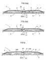
- a pushbutton switch 1 of the invention shown in Figs. 1 and 2 includes a fixed contact 3 which is constituted from a substrate 2 and a portion of a circuit pattern 8 provided on the substrate 2 and a movable contact 4 formed of a thin conductive plate made of e.g. metal configured as a dome-like member covering the fixed contact 3 from above.
- the fixed contact 3 includes a surface-devoid portion 5 formed by a through hole 50 which is formed originally in the substrate 2. This surface-devoid portion 5 creates an inner escape hollow space 31 and a contact edge 30 along its periphery.
- the movable contact 4 includes a projection 6 which is convex downwardly, that is, convex toward the fixed contact 3.
- the projection 6 or its periphery of the movable contact 4 comes into contact with the contact edge 30 of the surface-devoid portion 5 of the fixed contact 3.
- the movable contact 4 is restored by its own resilience to move its projection 5 away from the surface of the fixed contact 3.
- the escape hollow space 31 provides a function of allowing "escape” or refuge of a foreign substance therein and discharging it therefrom and another function of allowing insertion of the projection 5 during an ON operation of the pushbutton switch 1.
- the projection 6 is configured as a dome or circular conical portion, whereas the surface-devoid portion 5 is formed with a circular cross section.
- the diameter: D of the root of the dome or cone-like projection 6 is greater than the diameter of the surface-devoid portion 5, that is, the diameter: d of the contact edge 30.
- the movable contact 4 is disposed to cover the area of the substrate forming the fixed contact 3 so that the projection 6 of the former is disposed in opposition to the surface-devoid portion 5 of the latter, and the movable contact 4 is fixed, in this condition, to the substrate 2 by means of a fixing tape 7 which is a flexible sheet. If the circuit patter 8 is formed on the opposite side of the substrate to the side of the pushbutton switch 1, then, the fixed contact 3 will be formed on this opposite side by extending the circuit patter through the thorough hole. In this case, this through hole will form the through hole 50 as the surface-devoid portion 5.
- this pushbutton switch 1 when this pushbutton switch 1 is pressed through the fixing tape 7 from the above with a finger, a tool or the like, the movable contact 4 will come into contact with the fixed contact 3. Upon release of the finger, tool or the like therefrom, the movable contact 4 will be restored by its own resilience back to its original position away from the fixed contact 3. In these manners, the pushbutton switch 1 is turned ON/OFF.
- the projection 6 and the surface-devoid portion 5 each have a circular cross section. Then, the contact condition between the movable contact 4 and the fixed contact 3, more particularly between the projection 6 of the former and the contact edge 30 of the latter, is realized as a line contact along the circle. If the surface-devoid portion 5 is formed with a polygonal cross section such as a rectangular cross section, then, the contact between the projection 6 and the contact edge 30 will be realized as a multiple-point contact.
- the center of the surface-devoid portion 6 is aligned with the center of the projection.
- the switch may be assembled with the center of the movable contact 4 offset to the right or left relative to the center of the fixed contact 3. In such case, the center of the surface-devoid portion 5 will not be aligned with the center of the projection 6.
- the multiple-point contact condition may be maintained. Only, a certain portion of the line contact will be pressed strongly while another or other portions will be hardly pressed. Further, if the projection has an inclined lateral face, the flexibility of the movable contact 4 per se may serve to guide the projection 6 to the contact edge 30 and then into the escape hollow space 31.
- Figs. 5 (a) and 5 (b) show a pushbutton switch 1 having three projections 6.
- the respective projections 6 come into contact with the contact edge 30 or its peripheral area of the surface-devoid portion 5.
- the projecting area formed by the three projections 6 is delimited to an area including the plural projections 6 denoted with dot lines and this projection area has a diameter greater than the diameter of the surface-devoid portion 5.
- a plurality of surface-devoid portions 5 may be provided each in correspondence with each of the plurality of projections 6.
Landscapes
- Push-Button Switches (AREA)
Abstract
Description
Claims (9)
- A pushbutton switch (1) having a fixed contact portion (3) provided on a substrate (2) and an elastically deformable movable contact portion (4) provided in opposition to a surface of the fixed contact portion, the movable contact portion being configured as a dome-like portion forming a greater gap relative to the surface of the fixed contact portion at a center portion of the surface than at a peripheral portion of the surface;
characterized in that
the fixed contact portion (3) includes, at a center portion on the surface thereof, a surface-devoid portion (5) forming a contact edge (30) in cooperation with the surface, and the movable contact portion (4) includes a projection (6) projecting toward the surface-devoid portion of the fixed contact portion, wherein, when a press force is applied to the movable contact portion (4), the movable contact portion is elastically deformed against resilience thereof toward the contact edge (30) to come into contact with the edge or an area adjacent thereto, and when the press force is released, the movable contact portion (4) is elastically restored to move its projection (6) away from the contact edge (30) or the adjacent area. - The pushbutton switch according to claim 1, characterized in that the surface-devoid portion (5) and the projection (6) are sized relative to each other in such a way as to allow at least a portion of the projection to enter the surface-devoid portion when the movable contact portion (4) is elastically deformed.
- The pushbutton switch according to claim 2, characterized in that the contact edge (30) is formed circular and the projection (6) is configured as a circular dome or a cone having a root with a diameter (D) greater than a diameter (d) of the contact edge.
- The pushbutton switch according to any one of claims 1-3, characterized in that the pushbutton switch includes a plurality of said projections (6).
- The pushbutton switch according to claim 4, characterized in that the pushbutton switch includes a plurality of said surface-devoid portions (5) in correspondence with the plurality of projections (6) respectively.
- The pushbutton switch according to any one of claims 1-5, characterized in that the surface-devoid portion (5) is provided as a recess (51).
- The pushbutton switch according to any one of claims 1-5, characterized in that the surface-devoid portion (5) is provided as a through hole (50).
- The pushbutton switch according to any one of claims 1-7, characterized in that the fixed contact portion (3) is provided as a portion of a circuit pattern (8) formed on the substrate (2).
- The pushbutton switch according to any one of claims 1-8, characterized in that a flexible sheet (7) is provided for covering and supporting the movable contact portion (4).
Applications Claiming Priority (2)
| Application Number | Priority Date | Filing Date | Title |
|---|---|---|---|
| JP2000348063A JP3765723B2 (en) | 2000-11-15 | 2000-11-15 | Push-button switch |
| JP2000348063 | 2000-11-15 |
Publications (2)
| Publication Number | Publication Date |
|---|---|
| EP1207543A2 true EP1207543A2 (en) | 2002-05-22 |
| EP1207543A3 EP1207543A3 (en) | 2004-08-18 |
Family
ID=18821704
Family Applications (1)
| Application Number | Title | Priority Date | Filing Date |
|---|---|---|---|
| EP01126944A Withdrawn EP1207543A3 (en) | 2000-11-15 | 2001-11-13 | Pushbutton switch |
Country Status (7)
| Country | Link |
|---|---|
| US (1) | US20020092753A1 (en) |
| EP (1) | EP1207543A3 (en) |
| JP (1) | JP3765723B2 (en) |
| KR (1) | KR100483648B1 (en) |
| CN (1) | CN1363942A (en) |
| HK (1) | HK1045213A1 (en) |
| TW (1) | TW516695U (en) |
Cited By (2)
| Publication number | Priority date | Publication date | Assignee | Title |
|---|---|---|---|---|
| WO2005045867A1 (en) * | 2003-11-06 | 2005-05-19 | Philip Adrian Sjostrom | Switch element |
| WO2009003532A1 (en) * | 2007-07-03 | 2009-01-08 | Sony Ericsson Mobile Communications Ab | An input device and an electronic device comprising an input device |
Families Citing this family (6)
| Publication number | Priority date | Publication date | Assignee | Title |
|---|---|---|---|---|
| TWI236690B (en) * | 2002-09-11 | 2005-07-21 | Fujikura Ltd | Membrane for key switch and the key switch |
| JP4088577B2 (en) * | 2003-10-16 | 2008-05-21 | ホシデン株式会社 | Movable contact for push-on switch and push-on switch |
| US11229737B2 (en) | 2014-09-10 | 2022-01-25 | Becton, Dickinson And Company | Activation system and method for on-body medical devices |
| CN104282467A (en) * | 2014-09-22 | 2015-01-14 | 三日科学技术(天津)有限公司 | Touch switch electronic component |
| CN108198721A (en) * | 2018-01-23 | 2018-06-22 | 深圳市东强精密塑胶电子有限公司 | A kind of novel ultra-thin touch-switch |
| TWI792753B (en) * | 2021-12-09 | 2023-02-11 | 群光電子股份有限公司 | Key structure |
Family Cites Families (8)
| Publication number | Priority date | Publication date | Assignee | Title |
|---|---|---|---|---|
| US3749859A (en) * | 1972-04-19 | 1973-07-31 | Colorado Instr Inc | Keyboard switch assembly with improved hermetically sealed diaphragm contact structure |
| US3796843A (en) * | 1973-01-02 | 1974-03-12 | Bomar Instr Corp | Calculator keyboard switch with disc spring contact and printed circuit board |
| US4033030A (en) * | 1974-09-12 | 1977-07-05 | Mohawk Data Sciences Corporation | Method of manufacturing keyswitch assemblies |
| US4375017A (en) * | 1976-12-06 | 1983-02-22 | Rca Corporation | Calculator type keyboard including printed circuit board contacts and method of forming |
| JPH01235108A (en) * | 1988-03-16 | 1989-09-20 | Fujitsu Ltd | Structure for membrane switch |
| FR2660484B1 (en) * | 1990-03-30 | 1993-08-06 | Sextant Avionique | MINIATURE TOUCH SWITCH DEVICE. |
| JPH10261338A (en) * | 1997-03-19 | 1998-09-29 | Teikoku Tsushin Kogyo Co Ltd | Membrane switch |
| JP2000149707A (en) * | 1998-11-06 | 2000-05-30 | Japan Aviation Electronics Industry Ltd | Dome contact switch |
-
2000
- 2000-11-15 JP JP2000348063A patent/JP3765723B2/en not_active Expired - Fee Related
-
2001
- 2001-10-22 TW TW090218014U patent/TW516695U/en not_active IP Right Cessation
- 2001-11-02 KR KR10-2001-0068099A patent/KR100483648B1/en not_active Expired - Fee Related
- 2001-11-13 US US10/007,635 patent/US20020092753A1/en not_active Abandoned
- 2001-11-13 EP EP01126944A patent/EP1207543A3/en not_active Withdrawn
- 2001-11-14 CN CN01144841A patent/CN1363942A/en active Pending
-
2002
- 2002-09-09 HK HK02106633.8A patent/HK1045213A1/en unknown
Cited By (3)
| Publication number | Priority date | Publication date | Assignee | Title |
|---|---|---|---|---|
| WO2005045867A1 (en) * | 2003-11-06 | 2005-05-19 | Philip Adrian Sjostrom | Switch element |
| WO2009003532A1 (en) * | 2007-07-03 | 2009-01-08 | Sony Ericsson Mobile Communications Ab | An input device and an electronic device comprising an input device |
| US7829812B2 (en) | 2007-07-03 | 2010-11-09 | Sony Ericsson Mobile Communications Ab | Input device and an electronic device comprising an input device |
Also Published As
| Publication number | Publication date |
|---|---|
| JP2002150876A (en) | 2002-05-24 |
| EP1207543A3 (en) | 2004-08-18 |
| US20020092753A1 (en) | 2002-07-18 |
| KR100483648B1 (en) | 2005-04-18 |
| KR20020037677A (en) | 2002-05-22 |
| CN1363942A (en) | 2002-08-14 |
| TW516695U (en) | 2003-01-01 |
| HK1045213A1 (en) | 2002-11-15 |
| JP3765723B2 (en) | 2006-04-12 |
Similar Documents
| Publication | Publication Date | Title |
|---|---|---|
| EP1065687B1 (en) | Sheet with movable contacts and sheet switch | |
| US6593537B2 (en) | Membrane switch | |
| EP1056106B1 (en) | Push button switch including dome-shaped movable contact having reverse function | |
| US6512827B1 (en) | Portable terminal device | |
| EP1137026B1 (en) | Push switch | |
| US20020092753A1 (en) | Pushbutton switch | |
| GB2321134A (en) | An assembly for a keypad | |
| JP5267077B2 (en) | Membrane switch | |
| EP1180777A2 (en) | Sheet having moving contacts and sheet switch | |
| EP1065688A2 (en) | Sheet with movable contacts and sheet switch | |
| JP2001035305A (en) | Air escape structure of dome switch | |
| KR100352491B1 (en) | Key pad assembly for mobile communica tion apparatus | |
| KR200224291Y1 (en) | Multi way switch | |
| US7329823B2 (en) | Movable contact element and panel switch formed using the same | |
| JP3128436B2 (en) | Push button switch | |
| KR102740165B1 (en) | Switch | |
| KR102107421B1 (en) | Metal dome switch for keypad | |
| JPH069400Y2 (en) | Membrane switch | |
| JPH0729450A (en) | Tact switch | |
| JP2008123945A (en) | Push button switch | |
| JP2872304B2 (en) | Keyboard switch | |
| JP2004139997A (en) | Push-button switch | |
| JPH0658774B2 (en) | Push button switch | |
| JPH0732832U (en) | Push switch | |
| JP2514177Y2 (en) | Push button switch |
Legal Events
| Date | Code | Title | Description |
|---|---|---|---|
| PUAI | Public reference made under article 153(3) epc to a published international application that has entered the european phase |
Free format text: ORIGINAL CODE: 0009012 |
|
| AX | Request for extension of the european patent |
Free format text: AL;LT;LV;MK;RO;SI |
|
| PUAL | Search report despatched |
Free format text: ORIGINAL CODE: 0009013 |
|
| AK | Designated contracting states |
Kind code of ref document: A3 Designated state(s): AT BE CH CY DE DK ES FI FR GB GR IE IT LI LU MC NL PT SE TR |
|
| AX | Request for extension of the european patent |
Extension state: AL LT LV MK RO SI |
|
| AKX | Designation fees paid | ||
| REG | Reference to a national code |
Ref country code: DE Ref legal event code: 8566 |
|
| STAA | Information on the status of an ep patent application or granted ep patent |
Free format text: STATUS: THE APPLICATION IS DEEMED TO BE WITHDRAWN |
|
| 18D | Application deemed to be withdrawn |
Effective date: 20050219 |
|
| REG | Reference to a national code |
Ref country code: HK Ref legal event code: WD Ref document number: 1045213 Country of ref document: HK |