EP1207212A2 - Nickel alloy composition - Google Patents
Nickel alloy composition Download PDFInfo
- Publication number
- EP1207212A2 EP1207212A2 EP01309670A EP01309670A EP1207212A2 EP 1207212 A2 EP1207212 A2 EP 1207212A2 EP 01309670 A EP01309670 A EP 01309670A EP 01309670 A EP01309670 A EP 01309670A EP 1207212 A2 EP1207212 A2 EP 1207212A2
- Authority
- EP
- European Patent Office
- Prior art keywords
- alloy composition
- nickel alloy
- blade
- tip
- gas turbine
- Prior art date
- Legal status (The legal status is an assumption and is not a legal conclusion. Google has not performed a legal analysis and makes no representation as to the accuracy of the status listed.)
- Granted
Links
Images

Classifications
-
- B—PERFORMING OPERATIONS; TRANSPORTING
- B23—MACHINE TOOLS; METAL-WORKING NOT OTHERWISE PROVIDED FOR
- B23P—METAL-WORKING NOT OTHERWISE PROVIDED FOR; COMBINED OPERATIONS; UNIVERSAL MACHINE TOOLS
- B23P6/00—Restoring or reconditioning objects
- B23P6/002—Repairing turbine components, e.g. moving or stationary blades, rotors
- B23P6/007—Repairing turbine components, e.g. moving or stationary blades, rotors using only additive methods, e.g. build-up welding
-
- B—PERFORMING OPERATIONS; TRANSPORTING
- B23—MACHINE TOOLS; METAL-WORKING NOT OTHERWISE PROVIDED FOR
- B23K—SOLDERING OR UNSOLDERING; WELDING; CLADDING OR PLATING BY SOLDERING OR WELDING; CUTTING BY APPLYING HEAT LOCALLY, e.g. FLAME CUTTING; WORKING BY LASER BEAM
- B23K35/00—Rods, electrodes, materials, or media, for use in soldering, welding, or cutting
- B23K35/22—Rods, electrodes, materials, or media, for use in soldering, welding, or cutting characterised by the composition or nature of the material
- B23K35/24—Selection of soldering or welding materials proper
- B23K35/30—Selection of soldering or welding materials proper with the principal constituent melting at less than 1550°C
- B23K35/3033—Ni as the principal constituent
- B23K35/304—Ni as the principal constituent with Cr as the next major constituent
-
- C—CHEMISTRY; METALLURGY
- C22—METALLURGY; FERROUS OR NON-FERROUS ALLOYS; TREATMENT OF ALLOYS OR NON-FERROUS METALS
- C22C—ALLOYS
- C22C19/00—Alloys based on nickel or cobalt
- C22C19/03—Alloys based on nickel or cobalt based on nickel
- C22C19/05—Alloys based on nickel or cobalt based on nickel with chromium
- C22C19/051—Alloys based on nickel or cobalt based on nickel with chromium and Mo or W
- C22C19/057—Alloys based on nickel or cobalt based on nickel with chromium and Mo or W with the maximum Cr content being less 10%
-
- C—CHEMISTRY; METALLURGY
- C22—METALLURGY; FERROUS OR NON-FERROUS ALLOYS; TREATMENT OF ALLOYS OR NON-FERROUS METALS
- C22C—ALLOYS
- C22C19/00—Alloys based on nickel or cobalt
- C22C19/03—Alloys based on nickel or cobalt based on nickel
- C22C19/05—Alloys based on nickel or cobalt based on nickel with chromium
- C22C19/058—Alloys based on nickel or cobalt based on nickel with chromium without Mo and W
-
- F—MECHANICAL ENGINEERING; LIGHTING; HEATING; WEAPONS; BLASTING
- F01—MACHINES OR ENGINES IN GENERAL; ENGINE PLANTS IN GENERAL; STEAM ENGINES
- F01D—NON-POSITIVE DISPLACEMENT MACHINES OR ENGINES, e.g. STEAM TURBINES
- F01D5/00—Blades; Blade-carrying members; Heating, heat-insulating, cooling or antivibration means on the blades or the members
- F01D5/12—Blades
- F01D5/14—Form or construction
- F01D5/20—Specially-shaped blade tips to seal space between tips and stator
-
- F—MECHANICAL ENGINEERING; LIGHTING; HEATING; WEAPONS; BLASTING
- F01—MACHINES OR ENGINES IN GENERAL; ENGINE PLANTS IN GENERAL; STEAM ENGINES
- F01D—NON-POSITIVE DISPLACEMENT MACHINES OR ENGINES, e.g. STEAM TURBINES
- F01D5/00—Blades; Blade-carrying members; Heating, heat-insulating, cooling or antivibration means on the blades or the members
- F01D5/12—Blades
- F01D5/28—Selecting particular materials; Particular measures relating thereto; Measures against erosion or corrosion
Definitions
- the present invention relates to a nickel alloy composition.
- the invention relates to a nickel alloy composition for application to the tips of gas turbine blades to act as an oxidation and corrosion resistant barrier.
- the nickel-based alloy composition consists essentially of about 14 to about 18 wt% Cr, about 6.45 to about 6.95 wt% Al, about 9.75 to about 11.45 wt% Co, about 5.95 to about 6.55 wt% Ta, about 1.85 to about 2.35 wt% Re, about 0.05 to about 1.75 wt% Hf, about 0.006 to about 0.03 wt% Zr, about 0.02 to about 0.11 wt% C, up to about 1.1 wt% Si, and up to about 0.01 wt% B, with the balance being nickel and typical impurities.
- the alloy can be deposited by a known laser deposition process to provide a so-called squealer (38), being a wall extending from the blade tip (12) and enclosing a tip well.
- the bottom of the tip well is defined by the surface of the blade tip (12).
- a nickel alloy composition comprising about 4 to about 8 (e.g. about 4.5 to about 6.5) wt% Cr, about 5 to about 6.5 (e.g. about 5.5 to about 6.2) wt% Al, about 2 to about 6 (e.g. about 3 to about 4) wt% Co, about 4 to about 8 (e.g. about 5 to about 7) wt% Ta, about 3 to about 5 (e.g. about 3.5 to about 4.5) wt% Re, about 0.1 to about 0.5 (e.g. about 0.1 to about 0.2) wt% Hf, about 0.04 to about 0.1 (e.g.
- wt% C about 0.04 to about 0.06) wt% C, about 0.05 to about 0.3 (e.g. about 0.05 to about 0.15) wt% Si, and about 0.003 to about 0.01 (e.g. about 0.003 to about 0.007) wt% B, with at least the major part (e.g. at least about 85%, more particularly at least about 90%) of the balance being nickel.
- the nickel alloy composition of the present invention preferably substantially excludes at least one (most preferably all) of Mo, Ti and V, and still more preferably excludes all of Mo, Ti, V and Nb. These elements are found generally to harm the resistance of the alloy to high temperature oxidation and corrosion.
- the nickel alloy composition of the present invention further includes one or more additional element selected from up to about 5 (e.g. about 1 to about 3) wt% W, up to about 5 (e.g. up to about 1) wt% Pt, up to about 0.008 (e.g. about 0.003 to about 0.008, more particularly about 0.003 to about 0.005) wt% La, and up to about 0.008 (e.g. about 0.003 to about 0.008, more particularly about 0.003 to about 0.005) wt% Y.
- additional element selected from up to about 5 (e.g. about 1 to about 3) wt% W, up to about 5 (e.g. up to about 1) wt% Pt, up to about 0.008 (e.g. about 0.003 to about 0.008, more particularly about 0.003 to about 0.005) wt% La, and up to about 0.008 (e.g. about 0.003 to about 0.008, more particularly about 0.003 to about 0.005) wt%
- the nickel alloy composition consists essentially of Cr, Al, Co, Ta, Re, Hf, C, Si, B and most preferably also one or more of W, Pt, La and Y, in the amounts stated above, the balance being nickel.
- W, Pt, La and Y it is most preferred that La and Y should be present, suitably in approximately equal amounts.
- the expression "consists essentially of” is to be understood as allowing for the presence of typical impurities, in addition to the stated elements.
- the nickel alloy composition has the nominal composition Cr (4.5 wt%), Al (6 wt%), Co (4 wt%), Ta (6 wt%), Re (4 wt%), Hf (0.15 wt%), C (0.05 wt%), Si (0.1 wt%), B (0.005 wt%), W (2 wt%), La (0.003-0.005 wt%), and Y (0.003 - 0.005 wt%), the remainder being nickel.
- Nickel alloy compositions substantially corresponding to the "nominal composition” set out above are also included within that definition.
- the nickel alloy composition of the present invention preferably comprises about 50% gamma prime volume fraction at room temperature and a gamma prime solvus of between about 1265 and about 1280 deg. C.
- the gamma prime regions will consist of Ni 3 (Al,Ta).
- the nickel alloy composition of the present invention preferably has, at elevated temperatures above about 800 deg. C, at least half the creep and the tensile and low cycle fatigue (LCF) strengths of conventional nickel-based superalloys (e.g. CMSX-4) from which gas turbine blades are typically cast, without substantially sacrificing oxidation and corrosion resistance, and more particularly high temperature oxidation and corrosion resistance.
- LCF tensile and low cycle fatigue
- the nickel alloy composition of the present invention may be provided in any suitable physical form for application to the tip of the gas turbine blade. As discussed below, it may be convenient in certain circumstances for the alloy composition to be provided in, for example, a physical form selected from powders, foils, rods and wires. Powders for use in a laser welding process may conveniently have a particle size range of +45/-140um.
- the use of the nickel alloy composition of the present invention for forming a blade tip of a gas turbine blade, particularly a blade tip of a gas turbine propulsion engine, to act as an oxidation and corrosion resistant barrier and optionally to provide the tip with rub tolerance.
- a method for forming a blade tip of a gas turbine blade comprising applying the nickel alloy composition of the first aspect of the present invention to the tip (i.e. the radially outermost portion) of the gas turbine blade.
- the formed blade tip may comprise a blade tip structure such as, for example, a squealer.
- the nickel alloy composition may be initially applied to a depth in excess of the desired alloy depth of the final formed blade tip or blade tip structure, and the applied nickel alloy composition subsequently machined to reduce the depth thereof to form the desired blade tip or blade tip structure.
- the step of applying the alloy composition to the tip of the gas turbine blade may preferably be accomplished by fusing the alloy composition onto the blade tip, preferably under controlled conditions whereby the desired configuration of the blade tip is achieved after cooling of the fused mass of the alloy composition.
- the step of applying the alloy composition to the tip of the blade is preferably carried out by means of a laser cladding process or by weld deposition process.
- the nickel alloy composition is provided initially in the form of a powder and is applied (e.g. as a layer) to the tip of the gas turbine blade by fusing the powder alloy to the tip of the gas turbine blade.
- a laser beam is directed at the selected superalloy surface of the gas turbine blade, and the finely divided nickel alloy powder according to the first aspect of the present invention is fed directly into the laser beam impingement zone.
- the energy density of the laser beam is sufficient to melt the nickel alloy powder, causing the powder particles to fuse to the superalloy surface of the gas turbine blade and to each other, thereby forming a homogeneous layer of relatively high density.
- the particles of the nickel alloy powder are sintered to the blade surface to provide the required barrier layer.
- the laser cladding process is particularly shape-faithful, making available shaping accuracies of +/- 0.04mm in the laying down of the alloy of the present invention. Where the configuration of the final form is critical, laser cladding may be preferred for this reason, as it can lead to savings of time and money in subsequent machining and other post-processing stages.
- the nickel alloy composition is initially provided in any convenient physical form, for example in rod or wire form, and is applied to the tip of the gas turbine blade by feeding the alloy composition into a plume or arc of a welding torch and onto the surface of the blade tip. In this process, the nickel alloy composition is fused to the blade surface to provide the required barrier layer.
- the deposited nickel alloy layer provides a high integrity treatment for the tips of turbine blades, e.g. shroudless turbine blades, in a gas turbine, and in particular in a gas turbine propulsion engine.
- the method for forming a blade tip may alternatively comprise a repair method for repairing damage to a metal article such as a cast metal turbine component, more particularly a turbine blade, a turbine shroud segment or a nozzle guide vane.
- a repair method for repairing damage to a metal article such as a cast metal turbine component, more particularly a turbine blade, a turbine shroud segment or a nozzle guide vane.
- a method for repairing a metal article such as, for example, a cast metal turbine component (e.g. a turbine blade, a turbine shroud segment or a nozzle guide vane), the method comprising applying the nickel alloy composition of the first aspect of the invention to a damaged portion of the metal article to repair the same.
- a cast metal turbine component e.g. a turbine blade, a turbine shroud segment or a nozzle guide vane
- the method for repairing a metal article such as, for example, a cast metal turbine component.
- the alloy composition of the present invention will be applied to the metal article to form initially a repair structure, which is typically subsequently machined to arrive at the final desired repaired configuration.
- a turbine blade 1 of a gas turbine propulsion engine has a geometry which is generally conventional in the art.
- the blade 1 has a root 2 and a tip 3, the tip 3 being provided with a squealer comprising a peripheral wall 4.
- the squealer serves in operation to enclose a body of relatively cool air at the tip of the blade in the tip well bounded by the wall 4. Holes (not shown) in the tip of the blade provide for air flow communication between hollow chambers within the blade and the said body of relatively cool air.
- the blade is preferably formed from a suitable high temperature material, such as an appropriate nickel-based superalloy of a type known in the art, and may be cast as single crystal or directionally solidified casting to promote the high temperature properties of the blade 1.
- a suitable high temperature material such as an appropriate nickel-based superalloy of a type known in the art
- the wall 4 of the squealer tip is formed using the novel nickel alloy composition of the first aspect of the invention.
- a representative composition of the alloy composition is substantially as follows: Cr (4.5 wt%), Al (6 wt%), Co (4 wt%), Ta (6 wt%), Re (4 wt%), Hf (0.15 wt%), C (0.05 wt%), Si (0.1 wt%), B (0.005 wt%), W (2 wt%), La (0.003-0.005 wt%), and Y (0.003 - 0.005 wt%), the remainder being nickel.
- the alloy composition is first formed by a conventional alloying process, as will be well within the abilities of one of ordinary skill in the art.
- the alloy composition is suitably initially prepared as an ingot, from with any desired physical form for the blade tip formation can be formed by conventional methods.
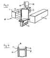
- a laser cladding process is employed for the initial laying down of the alloy composition, as illustrated more particularly in Figures 2 and 3 of the drawings.
- the tip 3 of the blade 1 is arranged under a conventional laser cladding apparatus 10, such as, for example, a Sulzer Metco laser welding apparatus available from Sulzer Metco Holding AG (Wohlen, Switzerland; web: www.sulzermetco.com ; tel: +41 56 618 8181).
- the apparatus includes lateral preheat boxes 11,12, each of which includes a quartz heating lamp 13, and an alloy powder feed line 14 extending from the powder feed system (not shown) to the laser beam tube 15.
- the laser beam tube 15 directs a laser beam to the blade tip 3.
- the alloy powder (suitably having a particle size range +45/-140um) enters the laser beam in close proximity to the surface of the blade 1 as it moves relative to the beam, to cause the powder to melt in the laser beam and fuse to the blade surface.
- the laser beam may be produced by any suitable laser source, such as a carbon dioxide laser with a power output of between about 1 and about 5 kilowatts. Conventional means for focussing the laser beam are provided in the apparatus.
- the laser cladding process involves irradiating a portion of the blade surface with the laser beam, so that a relatively small molten pool of the superalloy of the blade surface is formed.
- the powdered alloy of the present invention is fed into the pool and dispersed therein at a rate of between about 0.1 and about 0.4 grams per second through a nozzle 16 of the apparatus via a stream of an inert gas such as argon.
- the powder particles fuse into the molten pool, which is then caused to solidify when the laser beam is moved away.
- the solidification of the molten pool if preferably effected rapidly, to minimise the formation of gamma prime phases in the alloy.
- Figure 2 shows by arrows A the peripheral deposition line followed in the laser cladding process, by which an unfinished wall 4a of the deposited alloy composition of the present invention, typically about 0.2 mm thicker than the intended ultimate height of the intended finished wall 4, is initially laid down on the blade tip 3.
- the initial deposition may conventiently lay down an unfinished wall 4a of height about 0.7 mm.
- the unfinished wall 4a is machined back to the desired height (e.g. about 0.5 mm) and configuration, using a conventional abrasion process.
- the cross-sectional profile of the resultant squealer is shown in Figure 4, in which numeral 16 represents the material of the blade and numeral 17 represents the deposited material of the novel alloy composition of the present invention.
- the alloy, process and use of the present invention enables gas turbine blade tips to be formed with acceptable strength (particularly tensile and low cycle fatigue (LCF) strength), creep and high temperature oxidation and corrosion resistance properties, from an alloy composition which is cheaper than conventional alloys and can be deposited faster and more efficiently than conventional alloys, particularly when a laser cladding or weld deposition process is used.
- acceptable strength particularly tensile and low cycle fatigue (LCF) strength
- LCF low cycle fatigue
- the alloy composition of the present invention makes available, in gas turbine blade tip structures, strengths exceeding half the strength of the nickel-based single crystal superalloys from which the turbine blade itself is cast, substantially greater than the strengths conventionally achievable through the use of thermal sprayed and machined MCrAlY overlay coatings for the blade tips, together with the processing advantages mentioned above.
- the same alloy can serve as a repair medium, in methods for repairing damage to a range of metal articles, particularly cast metal turbine components such as turbine blades, turbine shroud segments or nozzle guide vanes.
Landscapes
- Engineering & Computer Science (AREA)
- Mechanical Engineering (AREA)
- Chemical & Material Sciences (AREA)
- Materials Engineering (AREA)
- General Engineering & Computer Science (AREA)
- Metallurgy (AREA)
- Organic Chemistry (AREA)
- Turbine Rotor Nozzle Sealing (AREA)
- Laser Beam Processing (AREA)
Abstract
Description
Claims (15)
- A nickel alloy composition comprising about 4 to about 8 wt% Cr, about 5 to about 6.5 wt% Al, about 2 to about 6 wt% Co, about 4 to about 8 wt% Ta, about 3 to about 5 wt% Re, about 0.1 to about 0.5 wt% Hf, about 0.04 to about 0.1 wt% C, about 0.05 to about 0.3 wt% Si, and about 0.003 to about 0.01 wt% B, with at least the major part of the balance being nickel.
- A nickel alloy composition as claimed in claim 1, substantially excluding at least one of Mo, Ti and V.
- A nickel alloy composition as claimed in claim 1 or claim 2, substantially excluding all of Mo, Ti, V and Nb.
- A nickel alloy composition as claimed in any one of the preceding claims, further including one or more element selected from up to about 5 wt% W, up to about 5 wt% Pt, about 0.003 to about 0.008 wt% La, and about 0.003 to about 0.008 wt% Y.
- A nickel alloy composition as claimed in any one of the preceding claims, wherein the composition consists essentially of Cr, Al, Co, Ta, Re, Hf, C, Si, B and optionally one or more of W, Pt, La and Y, in the amounts stated in the said preceding claim, the balance being nickel.
- A nickel alloy composition, substantially as defined by the nominal composition: Cr 4.5 wt%; Al 6 wt%; Co 4 wt%; Ta 6 wt%; Re 4 wt%; Hf 0.15 wt%; C 0.05 wt%; Si 0.1 wt%; B 0.005 wt%; W 2 wt%; La 0.003-0.005 wt%; and Y 0.003-0.005 wt%; the remainder being nickel.
- The use of a nickel alloy composition as defined in any one of the preceding claims, for forming a blade tip of a gas turbine blade, particularly a blade tip of a gas turbine propulsion engine, to act as an oxidation and corrosion resistant barrier and optionally to provide the tip with rub tolerance.
- A method for forming a blade tip of a gas turbine blade, particularly a blade tip of a gas turbine propulsion engine, the method comprising applying a nickel alloy composition as defined in any one of claims 1 to 6 to the tip of the gas turbine blade.
- A method for repairing a metal article, the method comprising applying a nickel alloy composition as defined in any one of claims 1 to 6 to a damaged portion of the metal article to repair the same.
- A method as claimed in claim 9, wherein the metal article is a cast metal turbine component.
- A method as claimed in claim 10, wherein the cast metal turbine component is a turbine blade, a turbine shroud segment or a nozzle guide vane.
- A method as claimed in any one of claims 8 to 11, wherein the application of the nickel alloy composition is carried out by a laser cladding or weld deposition process.
- A method for forming a blade tip or blade tip structure of a gas turbine blade, or for forming a repair structure to repair a cast metal turbine component, the method comprising laser cladding or weld depositing a nickel alloy composition as defined in any one of claims 1 to 6 to the tip of the gas turbine blade or to the cast metal turbine component, to a depth in excess of the desired blade tip or structure, and subsequently machining the nickel alloy composition to reduce the depth thereof to form the desired blade tip or structure.
- A method as claimed in claim 13, wherein the nickel alloy composition is applied by laser cladding.
- A method as claimed in claim 14 or claim 15, wherein the blade tip comprises a squealer.
Applications Claiming Priority (2)
| Application Number | Priority Date | Filing Date | Title |
|---|---|---|---|
| GB0028215 | 2000-11-18 | ||
| GBGB0028215.2A GB0028215D0 (en) | 2000-11-18 | 2000-11-18 | Nickel alloy composition |
Publications (3)
| Publication Number | Publication Date |
|---|---|
| EP1207212A2 true EP1207212A2 (en) | 2002-05-22 |
| EP1207212A3 EP1207212A3 (en) | 2002-09-11 |
| EP1207212B1 EP1207212B1 (en) | 2010-09-29 |
Family
ID=9903465
Family Applications (1)
| Application Number | Title | Priority Date | Filing Date |
|---|---|---|---|
| EP01309670A Expired - Lifetime EP1207212B1 (en) | 2000-11-18 | 2001-11-16 | Nickel alloy composition |
Country Status (4)
| Country | Link |
|---|---|
| US (3) | US20020068008A1 (en) |
| EP (1) | EP1207212B1 (en) |
| DE (1) | DE60143151D1 (en) |
| GB (1) | GB0028215D0 (en) |
Cited By (3)
| Publication number | Priority date | Publication date | Assignee | Title |
|---|---|---|---|---|
| CN102677046A (en) * | 2012-05-25 | 2012-09-19 | 唐山瑞兆激光技术机械修复有限公司 | Alloy composite special for laser cladding of rolling mill housings |
| EP2703507A1 (en) * | 2012-08-30 | 2014-03-05 | Hitachi Ltd. | Ni base alloy and gas turbine blade and gas turbine utilizing the same |
| CN105506383A (en) * | 2015-12-21 | 2016-04-20 | 常熟市梅李合金材料有限公司 | Nickel-chromium high-resistance electrothermal alloy |
Families Citing this family (22)
| Publication number | Priority date | Publication date | Assignee | Title |
|---|---|---|---|---|
| EP1725363B1 (en) * | 2004-02-18 | 2010-12-29 | Société d'exploitation Tarrerias Bonjean | Method of producing a cutting blade |
| US7316850B2 (en) | 2004-03-02 | 2008-01-08 | Honeywell International Inc. | Modified MCrAlY coatings on turbine blade tips with improved durability |
| US20060219329A1 (en) * | 2005-03-29 | 2006-10-05 | Honeywell International, Inc. | Repair nickel-based superalloy and methods for refurbishment of gas turbine components |
| US20060219330A1 (en) * | 2005-03-29 | 2006-10-05 | Honeywell International, Inc. | Nickel-based superalloy and methods for repairing gas turbine components |
| US20080022693A1 (en) * | 2005-09-30 | 2008-01-31 | Zoran Dicic | Ceramic blade gas turbine |
| US20100257733A1 (en) * | 2006-07-20 | 2010-10-14 | Honeywell International, Inc. | High pressure single crystal turbine blade tip repair with laser cladding |
| US20100052261A1 (en) * | 2008-09-03 | 2010-03-04 | Salvador Maldonado | Metallic seal for use in highly-corrosive oil and gas environments |
| US8216509B2 (en) * | 2009-02-05 | 2012-07-10 | Honeywell International Inc. | Nickel-base superalloys |
| US20100254822A1 (en) * | 2009-03-24 | 2010-10-07 | Brian Thomas Hazel | Super oxidation and cyclic damage resistant nickel-base superalloy and articles formed therefrom |
| US8449262B2 (en) * | 2009-12-08 | 2013-05-28 | Honeywell International Inc. | Nickel-based superalloys, turbine blades, and methods of improving or repairing turbine engine components |
| US8230899B2 (en) | 2010-02-05 | 2012-07-31 | Ati Properties, Inc. | Systems and methods for forming and processing alloy ingots |
| US9267184B2 (en) * | 2010-02-05 | 2016-02-23 | Ati Properties, Inc. | Systems and methods for processing alloy ingots |
| US10207312B2 (en) | 2010-06-14 | 2019-02-19 | Ati Properties Llc | Lubrication processes for enhanced forgeability |
| US8789254B2 (en) | 2011-01-17 | 2014-07-29 | Ati Properties, Inc. | Modifying hot workability of metal alloys via surface coating |
| US20120251840A1 (en) * | 2011-03-30 | 2012-10-04 | General Electric Company | Nickel-base weld materials, processes of using, and components formed therewith |
| US20130167979A1 (en) * | 2011-12-29 | 2013-07-04 | General Electric Company | Method of predicting quench cracking in components formed by high deformation processes |
| US8858873B2 (en) | 2012-11-13 | 2014-10-14 | Honeywell International Inc. | Nickel-based superalloys for use on turbine blades |
| US9539636B2 (en) | 2013-03-15 | 2017-01-10 | Ati Properties Llc | Articles, systems, and methods for forging alloys |
| US9027374B2 (en) | 2013-03-15 | 2015-05-12 | Ati Properties, Inc. | Methods to improve hot workability of metal alloys |
| RU178559U1 (en) * | 2018-01-19 | 2018-04-09 | Акционерное общество "Научно-производственный центр газотурбостроения "Салют" (АО НПЦ газотурбостроения "Салют") | MULTI-LAYER PIPE BILL FOR FORMING A GAS TURBINE ENGINE DISC |
| US10933469B2 (en) | 2018-09-10 | 2021-03-02 | Honeywell International Inc. | Method of forming an abrasive nickel-based alloy on a turbine blade tip |
| CN110273150A (en) * | 2019-07-03 | 2019-09-24 | 中国石油集团渤海钻探工程有限公司 | A kind of superhard coating powder and its application |
Family Cites Families (44)
| Publication number | Priority date | Publication date | Assignee | Title |
|---|---|---|---|---|
| US4110110A (en) * | 1975-08-27 | 1978-08-29 | Mitsubishi Kinzoku Kabushiki Kaisha | Nickel-base alloy excellent in corrosion resistance at high temperatures |
| US4261742A (en) * | 1978-09-25 | 1981-04-14 | Johnson, Matthey & Co., Limited | Platinum group metal-containing alloys |
| GB2052566B (en) * | 1979-03-30 | 1982-12-15 | Rolls Royce | Laser aplication of hard surface alloy |
| US6054096A (en) * | 1982-12-27 | 2000-04-25 | United Technologies Corporation | Stable heat treatable nickel superalloy single crystal articles and compositions |
| DE3426201A1 (en) * | 1984-07-17 | 1986-01-23 | BBC Aktiengesellschaft Brown, Boveri & Cie., Baden, Aargau | PROCESS FOR APPLYING PROTECTIVE LAYERS |
| US4743733A (en) * | 1984-10-01 | 1988-05-10 | General Electric Company | Method and apparatus for repairing metal in an article |
| US4730093A (en) * | 1984-10-01 | 1988-03-08 | General Electric Company | Method and apparatus for repairing metal in an article |
| US5077141A (en) * | 1984-12-06 | 1991-12-31 | Avco Corporation | High strength nickel base single crystal alloys having enhanced solid solution strength and methods for making same |
| DE3571149D1 (en) * | 1985-03-13 | 1989-07-27 | Gen Electric | Yttrium and yttrium-silicon bearing nickel-base superalloys especially useful as compatible coatings for advanced superalloys |
| DE3683091D1 (en) * | 1985-05-09 | 1992-02-06 | United Technologies Corp | PROTECTIVE LAYERS FOR SUPER ALLOYS, WELL ADAPTED TO THE SUBSTRATES. |
| US4719080A (en) * | 1985-06-10 | 1988-01-12 | United Technologies Corporation | Advanced high strength single crystal superalloy compositions |
| GB2191917A (en) * | 1986-06-16 | 1987-12-23 | Ibm | A multiple window display system |
| GB2235697B (en) * | 1986-12-30 | 1991-08-14 | Gen Electric | Improved and property-balanced nickel-base superalloys for producing single crystal articles. |
| US4724299A (en) * | 1987-04-15 | 1988-02-09 | Quantum Laser Corporation | Laser spray nozzle and method |
| US4804815A (en) * | 1987-06-01 | 1989-02-14 | Quantum Laser Corporation | Process for welding nickel-based superalloys |
| US4777341A (en) * | 1987-08-18 | 1988-10-11 | Quantum Laser Corporation | Back reflection monitor and method |
| US4958058A (en) * | 1989-02-08 | 1990-09-18 | General Electric Company | Transverse flow laser spray nozzle |
| US5043548A (en) * | 1989-02-08 | 1991-08-27 | General Electric Company | Axial flow laser plasma spraying |
| US5038014A (en) * | 1989-02-08 | 1991-08-06 | General Electric Company | Fabrication of components by layered deposition |
| US5177865A (en) * | 1989-05-05 | 1993-01-12 | Mtu Motoren-Und Turbinen-Union | Method for making heat exchanger having at least two collecting pipes |
| US4998005A (en) * | 1989-05-15 | 1991-03-05 | General Electric Company | Machine vision system |
| US4995087A (en) * | 1989-05-15 | 1991-02-19 | General Electric Company | Machine vision system |
| US5112801A (en) * | 1990-01-24 | 1992-05-12 | The United States Of America As Represented By The United States Department Of Energy | Mechanical alignment of particles for use in fabricating superconducting and permanent magnetic materials |
| JPH06234082A (en) * | 1990-06-28 | 1994-08-23 | Kankoku Kikai Kenkyusho | Method for liquid phase diffusion bonding using insert material higher in melting temperature than base metal |
| DE4113791A1 (en) * | 1991-04-26 | 1992-10-29 | Solvay Deutschland | METHOD FOR THE SEPARATION OF A BOR AND NITROGEN CONTAINING LAYER |
| US5160822A (en) * | 1991-05-14 | 1992-11-03 | General Electric Company | Method for depositing material on the tip of a gas turbine engine airfoil using linear translational welding |
| US5298204A (en) * | 1992-02-12 | 1994-03-29 | General Motors Corporation | Method of burning out polycarbonate patterns from ceramic molds |
| US5245155A (en) * | 1992-03-06 | 1993-09-14 | General Electric Company | Single point powder feed nozzle for use in laser welding |
| EP0560296B1 (en) * | 1992-03-09 | 1998-01-14 | Hitachi Metals, Ltd. | Highly hot corrosion resistant and high-strength superalloy, highly hot corrosion resistant and high-strength casting having single crystal structure, gas turbine and combined cycle power generation system |
| US5395584A (en) * | 1992-06-17 | 1995-03-07 | Avco Corporation | Nickel-base superalloy compositions |
| US5366695A (en) * | 1992-06-29 | 1994-11-22 | Cannon-Muskegon Corporation | Single crystal nickel-based superalloy |
| US5352540A (en) * | 1992-08-26 | 1994-10-04 | Alliedsignal Inc. | Strain-tolerant ceramic coated seal |
| US5449536A (en) * | 1992-12-18 | 1995-09-12 | United Technologies Corporation | Method for the application of coatings of oxide dispersion strengthened metals by laser powder injection |
| US5477025A (en) * | 1994-01-14 | 1995-12-19 | Quantum Laser Corporation | Laser nozzle |
| US5584663A (en) * | 1994-08-15 | 1996-12-17 | General Electric Company | Environmentally-resistant turbine blade tip |
| US5814152A (en) * | 1995-05-23 | 1998-09-29 | Mcdonnell Douglas Corporation | Apparatus for coating a substrate |
| US5612099A (en) * | 1995-05-23 | 1997-03-18 | Mcdonnell Douglas Corporation | Method and apparatus for coating a substrate |
| DE19547903C1 (en) * | 1995-12-21 | 1997-03-20 | Mtu Muenchen Gmbh | Mfr. or repair of turbine blade tips using laser beam weld-coating and blade master alloy metal powder filler |
| EP0789087B1 (en) * | 1996-02-09 | 2000-05-10 | Hitachi, Ltd. | High strength Ni-base superalloy for directionally solidified castings |
| US5847357A (en) * | 1997-08-25 | 1998-12-08 | General Electric Company | Laser-assisted material spray processing |
| JP3184882B2 (en) * | 1997-10-31 | 2001-07-09 | 科学技術庁金属材料技術研究所長 | Ni-based single crystal alloy and method for producing the same |
| US6444057B1 (en) * | 1999-05-26 | 2002-09-03 | General Electric Company | Compositions and single-crystal articles of hafnium-modified and/or zirconium-modified nickel-base superalloys |
| US6468367B1 (en) * | 1999-12-27 | 2002-10-22 | General Electric Company | Superalloy weld composition and repaired turbine engine component |
| EP1184473B1 (en) * | 2000-08-30 | 2005-01-05 | Kabushiki Kaisha Toshiba | Nickel-base single-crystal superalloys, method of manufacturing same and gas turbine high temperature parts made thereof |
-
2000
- 2000-11-18 GB GBGB0028215.2A patent/GB0028215D0/en not_active Ceased
-
2001
- 2001-11-15 US US09/987,683 patent/US20020068008A1/en not_active Abandoned
- 2001-11-16 EP EP01309670A patent/EP1207212B1/en not_active Expired - Lifetime
- 2001-11-16 DE DE60143151T patent/DE60143151D1/en not_active Expired - Lifetime
-
2004
- 2004-02-18 US US10/779,664 patent/US20040234410A1/en not_active Abandoned
-
2005
- 2005-07-08 US US11/176,226 patent/US20060239852A1/en not_active Abandoned
Cited By (5)
| Publication number | Priority date | Publication date | Assignee | Title |
|---|---|---|---|---|
| CN102677046A (en) * | 2012-05-25 | 2012-09-19 | 唐山瑞兆激光技术机械修复有限公司 | Alloy composite special for laser cladding of rolling mill housings |
| CN102677046B (en) * | 2012-05-25 | 2013-08-07 | 河北瑞兆激光再制造技术有限公司 | Alloy composite special for laser cladding of rolling mill housings |
| EP2703507A1 (en) * | 2012-08-30 | 2014-03-05 | Hitachi Ltd. | Ni base alloy and gas turbine blade and gas turbine utilizing the same |
| EP2703507B1 (en) | 2012-08-30 | 2016-01-20 | Mitsubishi Hitachi Power Systems, Ltd. | Ni base alloy and gas turbine blade and gas turbine utilizing the same |
| CN105506383A (en) * | 2015-12-21 | 2016-04-20 | 常熟市梅李合金材料有限公司 | Nickel-chromium high-resistance electrothermal alloy |
Also Published As
| Publication number | Publication date |
|---|---|
| GB0028215D0 (en) | 2001-01-03 |
| US20020068008A1 (en) | 2002-06-06 |
| EP1207212A3 (en) | 2002-09-11 |
| US20040234410A1 (en) | 2004-11-25 |
| DE60143151D1 (en) | 2010-11-11 |
| EP1207212B1 (en) | 2010-09-29 |
| US20060239852A1 (en) | 2006-10-26 |
Similar Documents
| Publication | Publication Date | Title |
|---|---|---|
| EP1207212B1 (en) | Nickel alloy composition | |
| KR100593053B1 (en) | Process for laser welding superalloy articles | |
| JP5197929B2 (en) | Niobium silicide-based turbine components and related laser deposition methods | |
| US8726501B2 (en) | Method of welding single crystal turbine blade tips with an oxidation-resistant filler material | |
| EP0740977B1 (en) | Containerless method of producing crack free metallic articles | |
| US6495793B2 (en) | Laser repair method for nickel base superalloys with high gamma prime content | |
| EP1721697B2 (en) | Superalloy repair methods and inserts | |
| EP1689553B1 (en) | Methods for repair of single crystal superalloys by laser welding and products thereof | |
| EP3091096B1 (en) | Article and method for forming an article | |
| US20060054079A1 (en) | Forming structures by laser deposition | |
| US20090297701A1 (en) | Process for Repairing a Component with a Directional Microstructure | |
| EP3345718B1 (en) | Structure braze repair of hard-to-weld superalloy components using diffusion alloy insert | |
| CN103702793A (en) | Nickel-based alloy, use, and method | |
| JPH09110596A (en) | Method for repairing part for single crystal gas turbine engine and single crystal metal product for | |
| KR101934625B1 (en) | Laser build-up welding of high heat resistant super alloys by means of oscillating beam guidance | |
| JP2009502503A (en) | Method for repairing parts having base material of directional microstructure and the parts | |
| JP6838832B2 (en) | Welding filler for superalloys | |
| JP7233422B2 (en) | Highly oxidation resistant alloy for gas turbine applications | |
| EP3731987B1 (en) | Laser metal deposition with inoculation | |
| JP2006016671A (en) | Ni-based alloy member and manufacturing method thereof, turbine engine component, welding material and manufacturing method thereof |
Legal Events
| Date | Code | Title | Description |
|---|---|---|---|
| PUAI | Public reference made under article 153(3) epc to a published international application that has entered the european phase |
Free format text: ORIGINAL CODE: 0009012 |
|
| AX | Request for extension of the european patent |
Free format text: AL;LT;LV;MK;RO;SI |
|
| PUAL | Search report despatched |
Free format text: ORIGINAL CODE: 0009013 |
|
| RIC1 | Information provided on ipc code assigned before grant |
Free format text: 7C 22C 19/00 A, 7C 22C 19/05 B |
|
| AK | Designated contracting states |
Kind code of ref document: A3 Designated state(s): AT BE CH CY DE DK ES FI FR GB GR IE IT LI LU MC NL PT SE TR |
|
| AX | Request for extension of the european patent |
Free format text: AL;LT;LV;MK;RO;SI |
|
| 17P | Request for examination filed |
Effective date: 20021028 |
|
| AKX | Designation fees paid |
Designated state(s): DE FR GB |
|
| 17Q | First examination report despatched |
Effective date: 20031031 |
|
| GRAP | Despatch of communication of intention to grant a patent |
Free format text: ORIGINAL CODE: EPIDOSNIGR1 |
|
| GRAS | Grant fee paid |
Free format text: ORIGINAL CODE: EPIDOSNIGR3 |
|
| GRAA | (expected) grant |
Free format text: ORIGINAL CODE: 0009210 |
|
| AK | Designated contracting states |
Kind code of ref document: B1 Designated state(s): DE FR GB |
|
| REG | Reference to a national code |
Ref country code: GB Ref legal event code: FG4D |
|
| REF | Corresponds to: |
Ref document number: 60143151 Country of ref document: DE Date of ref document: 20101111 Kind code of ref document: P |
|
| PLBE | No opposition filed within time limit |
Free format text: ORIGINAL CODE: 0009261 |
|
| STAA | Information on the status of an ep patent application or granted ep patent |
Free format text: STATUS: NO OPPOSITION FILED WITHIN TIME LIMIT |
|
| 26N | No opposition filed |
Effective date: 20110630 |
|
| REG | Reference to a national code |
Ref country code: DE Ref legal event code: R097 Ref document number: 60143151 Country of ref document: DE Effective date: 20110630 |
|
| PGFP | Annual fee paid to national office [announced via postgrant information from national office to epo] |
Ref country code: DE Payment date: 20121128 Year of fee payment: 12 Ref country code: FR Payment date: 20121206 Year of fee payment: 12 |
|
| PGFP | Annual fee paid to national office [announced via postgrant information from national office to epo] |
Ref country code: GB Payment date: 20121126 Year of fee payment: 12 |
|
| REG | Reference to a national code |
Ref country code: DE Ref legal event code: R119 Ref document number: 60143151 Country of ref document: DE |
|
| GBPC | Gb: european patent ceased through non-payment of renewal fee |
Effective date: 20131116 |
|
| REG | Reference to a national code |
Ref country code: FR Ref legal event code: ST Effective date: 20140731 |
|
| PG25 | Lapsed in a contracting state [announced via postgrant information from national office to epo] |
Ref country code: DE Free format text: LAPSE BECAUSE OF NON-PAYMENT OF DUE FEES Effective date: 20140603 |
|
| REG | Reference to a national code |
Ref country code: DE Ref legal event code: R119 Ref document number: 60143151 Country of ref document: DE Effective date: 20140603 |
|
| PG25 | Lapsed in a contracting state [announced via postgrant information from national office to epo] |
Ref country code: FR Free format text: LAPSE BECAUSE OF NON-PAYMENT OF DUE FEES Effective date: 20131202 Ref country code: GB Free format text: LAPSE BECAUSE OF NON-PAYMENT OF DUE FEES Effective date: 20131116 |