EP1207101A2 - Variable camber leading edge for an airfoil - Google Patents
Variable camber leading edge for an airfoil Download PDFInfo
- Publication number
- EP1207101A2 EP1207101A2 EP01203799A EP01203799A EP1207101A2 EP 1207101 A2 EP1207101 A2 EP 1207101A2 EP 01203799 A EP01203799 A EP 01203799A EP 01203799 A EP01203799 A EP 01203799A EP 1207101 A2 EP1207101 A2 EP 1207101A2
- Authority
- EP
- European Patent Office
- Prior art keywords
- airfoil
- panel
- link
- variable camber
- bullnose
- Prior art date
- Legal status (The legal status is an assumption and is not a legal conclusion. Google has not performed a legal analysis and makes no representation as to the accuracy of the status listed.)
- Granted
Links
- 239000000725 suspension Substances 0.000 claims abstract description 40
- 230000007704 transition Effects 0.000 claims description 5
- 230000008901 benefit Effects 0.000 description 5
- 238000010276 construction Methods 0.000 description 4
- 238000007789 sealing Methods 0.000 description 3
- 230000009471 action Effects 0.000 description 2
- 230000006872 improvement Effects 0.000 description 2
- 230000036316 preload Effects 0.000 description 2
- 238000005452 bending Methods 0.000 description 1
- 230000007246 mechanism Effects 0.000 description 1
- 230000004048 modification Effects 0.000 description 1
- 238000012986 modification Methods 0.000 description 1
- 230000004044 response Effects 0.000 description 1
Images


Classifications
-
- B—PERFORMING OPERATIONS; TRANSPORTING
- B64—AIRCRAFT; AVIATION; COSMONAUTICS
- B64C—AEROPLANES; HELICOPTERS
- B64C3/00—Wings
- B64C3/38—Adjustment of complete wings or parts thereof
- B64C3/44—Varying camber
- B64C3/50—Varying camber by leading or trailing edge flaps
Definitions
- This invention relates to airfoil structures for fixed wing aircraft, and more particularly to a leading edge construction for an airfoil.
- VCK Variable Camber Kreuger
- leading edge flap design where even further improvement is desired is in the seal between the panel of the leading edge component and the airfoil, and also between the panel and bullnose of the leading edge component. Often it has been difficult to achieve an excellent seal between the panel/wing and panel/bullnose interface without the use of separate seal elements. An excellent seal formed at these areas, directly between the forward and rearward portions of the panel and the airfoil, would even further enhance the aerodynamic efficiency of the variable camber leading edge when the leading edge flap is in its takeoff and landing positions.
- variable camber leading edge flap is deployed from a retracted (i.e., cruise) position into either a takeoff or a landing position.
- Some designs of variable camber leading edge constructions when initially moved out of their retracted positions, tend to "scoop" air using the undersurface of the panel forming the variable camber leading edge assembly. It would be desirable to provide a leading edge construction which does not operate to scoop air when it is initially deployed from its retracted (i.e., cruise) position into either a takeoff or a landing position.
- the present invention relates to a Variable Camber Kreuger leading edge assembly for an airfoil of an aircraft.
- the leading edge assembly includes a variable camber panel which is hingedly secured to a bullnose.
- the panel/bullnose assembly is suspended from a lower surface of the airfoil by a forward suspension link and an aft suspension link operatively associated with a linkage assembly.
- the linkage assembly includes connections to the panel at three points along the panel.
- the linkage assembly is also coupled to the bullnose to cause the bullnose to be folded toward the panel when the leading edge assembly is in a cruise position.
- the bullnose In the cruise position the bullnose is folded toward the panel, and the panel forms a generally smooth, continuous lower surface of the airfoil.
- the aft suspension link As the aft suspension link is driven rotationally by a torque shaft of an actuator, the panel rotates outwardly from the lower area of the airfoil such that a leading edge of the panel moves at a greater rate of travel than the trailing edge of the panel.
- the bullnose also begins to unfold.
- the trailing edge of the panel is maintained close to a forwardmost leading edge of the airfoil to thus prevent the leading edge assembly from "scooping" air during this portion of movement.
- the forward and aft suspension links, together with the linkage assembly, continue to urge the panel/bullnose rotationally, with the bullnose continuing to unfold, until the panel/bullnose is in a landing position. In this position a gap exists between the trailing edge of the panel and the forwardmost leading edge of the airfoil.
- the bullnose is also rotated during this portion of movement so that it forms a generally smooth, continuous curvature with the panel when the panel reaches the landing position.
- the linkage assembly When the aft suspension link is rotated further it causes the linkage assembly to urge the panel/bullnose into a "take-off" position. In the take-off position the trailing edge of the panel abuts the forwardmost leading edge of the airfoil to form a smooth seal therebetween. A forwardmost edge of the panel also rests over a trailing edge of the bullnose to also form a smooth seal at this interface.
- the aft suspension link and linkage assembly When in the take-off position, the aft suspension link and linkage assembly form an especially strong truss-type load path to provide a highly rigid arrangement that is not susceptible to deflection in response to the high loads experienced during take-off.
- the sealing action provided by the leading and trailing edges of the panel eliminate the need for separate seals at the panel/bullnose interface and the panel/airfoil interface, thus also serving to reduce the cost of the leading edge assembly.
- VCM Variable Camber Kreuger
- the leading edge assembly 10 is suspended from the airfoil 12 by a forward suspension link 18 pivotably coupled at point 20 to the airfoil 12, and an aft suspension link 22 drivingly coupled at upper end 24 to a torque shaft 26a of an actuator 26.
- the aft suspension link 22 is comprised of an upper link 28 and a lower link 30 pivotably coupled at point 32.
- a lower end 34 of the forward suspension link 18 is pivotably coupled at point 36 with a portion of the lower link 30.
- the leading edge assembly 10 also comprises a bullnose 38 which is hingedly attached via a hinge at point 40 to a variable camber panel 42.
- the panel 42 has a leading, forwardmost edge 42a and a trailing edge 42b. Forwardmost edge 42a abuts against edge 16s to form a seal when the variable camber panel 42 is in the fully retraced position. Similarly, trailing edge 42b abuts edge 13 to form a seal when the panel 42 is in the retracted position. This sealing at the forward and rear portions of the panel 42 is thus accomplished without independent seal members.
- a scissors linkage assembly 44 includes a first link 46 pivotably coupled to an intermediate point of the forward suspension link 18 at point 48, a second link 50 pivotably coupled at pivot point 54 to a mounting structure 42c of the panel 42.
- a third scissors link 58 is pivotably coupled at point 60 to opposite ends of each of scissors links 50 and 44, and at an opposite end thereof at pivot point 62 to a portion of the lower link 30.
- a first extension link 64 is also pivotably coupled at a point 66 to the lower link 30 and at an opposite end thereof at point 68 to the bullnose 38.
- Link 50 is preferably a two piece link threadably coupled to allow adjustment of its overall length. This degree of adjustability allows a degree of preload to be achieved between surface 12a and trailing edge 42b when the panel 42 is in its cruise position.
- the bullnose 38 is also coupled via a short link 39 to pivot point 70, which is in turn coupled to a second extension link 72.
- An opposite end of the second extension link 72 is coupled to the mounting structure 42c at pivot point 54.
- An intermediate point of the second extension link 72 is also pivotably coupled at point 74 to the lower link 30.
- a support link 76 is operatively pivotably coupled at pivot point 78 to the lower link 30 and at its opposite end to the mounting structure 42c via pivot point 80.
- the approximate forwardmost half of the panel 42 (i.e., approximately between pivot points 40 and 80) comprises the variable camber portion of the panel 42.
- the approximate rear half of the panel 42 (i.e., the portion approximately between pivot points 80 and 54) represents the rigid portion of the panel 42.
- This link 30 is formed with an extending link 30a pivotally mounted at point 30b to a yoke assembly 30c.
- the yoke assembly 30c is in turn secured by a bolt 30d to an aft link member 30e.
- a threaded bolt 30f extends through an opening in a flange 30g of the extending link 30a.
- leading edge assembly 10 With initial reference to Figure 6, the leading edge assembly 10 is shown in the retracted or "cruise" position. In this position the airfoil 12 forms a highly aerodynamic shape suitable for high speed flight and panel 42 has a first degree of curvature. The bullnose 38 is folded within the recess 16 and panel 42 forms a smooth, integral portion of the lower surface 14 of the airfoil 12.
- An important advantage of the present invention is that the panel 42 is moved from the positions of Figures 3 and 4 into the position shown in Figure 2 without presenting the panel 42 in a position where it operates to scoop air into the recess 16. In this manner the aerodynamic efficiency of the airfoil 12 during deployment is improved significantly.
- FIG. 1 further clockwise rotation of the upper link 28 causes the trailing edge 42b of the panel 42 to abut the upper, forwardmost edge 12b of the airfoil 12 to form a relatively smooth, aerodynamic seal therebetween.
- this seal is formed without any separate sealing member or component being required at this interface.
- the leading edge assembly 10 is also shown in the take-off position in Figures 8 and 9, with the bullnose 38 and panel 42 omitted for clarity. In these views it can be seen that a pair of j-links 76, a pair of second links 50, a pair of first links 46, and a pair of forward suspension links 18 are employed to form the leading edge mechanism 10.
- the scissors linkage assembly 44 allows very good control of the position, angle and shape of the panel 42 of the assembly 10.
- the scissors assembly 44 also provides for quick auto-gapping of the leading edge assembly 10 if stall is imminent.
- leading edge assembly 10 of the present invention is that if the assembly 10 is overloaded when in the landing or take-off positions, the assembly 10 will collapse, thus avoiding damage to surrounding structure of the airfoil 12. This also ensures that the leading edge assembly 10 remains attached to the airfoil 12 in the event that unusually high aerodynamic forces are experienced which cause overloading of the leading edge assembly 10.
- the overlapping of the forwardmost leading edge 42a of the panel 42 over the bullnose 38 when the assembly 10 is urged into the landing or take-off positions eliminates the need for separate seals to be used at the panel/bullnose interface for landing and take-off, as well as eliminating the need for separate seals at the panel/airfoil interface when in the take-off position. This also serves to reduce weight, the number of parts required for the assembly 10, and thus the cost and complexity of the assembly.
Landscapes
- Engineering & Computer Science (AREA)
- Mechanical Engineering (AREA)
- Aviation & Aerospace Engineering (AREA)
- Special Spraying Apparatus (AREA)
- Air-Flow Control Members (AREA)
- Seal Device For Vehicle (AREA)
Abstract
Description
- This invention relates to airfoil structures for fixed wing aircraft, and more particularly to a leading edge construction for an airfoil.
- Present day state of the art commercial twin-engined aircraft use leading edge slats for controlling airflow over the fixed wings of the aircraft during takeoff, landing and cruise conditions. However, slats are heavy, expensive, cannot use common parts, and must use the high-speed (i.e., cruise) wingfoil shape in the extended, angled positions at takeoff and landing. Current production Variable Camber Kreuger (VCK) devices are two-position devices (cruise and gapped), which have excessive drag for takeoff. The VCK advantage is a more optimum aerodynamic shape.
- One specific area of leading edge flap design where even further improvement is desired is in the seal between the panel of the leading edge component and the airfoil, and also between the panel and bullnose of the leading edge component. Often it has been difficult to achieve an excellent seal between the panel/wing and panel/bullnose interface without the use of separate seal elements. An excellent seal formed at these areas, directly between the forward and rearward portions of the panel and the airfoil, would even further enhance the aerodynamic efficiency of the variable camber leading edge when the leading edge flap is in its takeoff and landing positions.
- Still another area where even further improvement would be desirable is in the manner in which the variable camber leading edge flap is deployed from a retracted (i.e., cruise) position into either a takeoff or a landing position. Some designs of variable camber leading edge constructions, when initially moved out of their retracted positions, tend to "scoop" air using the undersurface of the panel forming the variable camber leading edge assembly. It would be desirable to provide a leading edge construction which does not operate to scoop air when it is initially deployed from its retracted (i.e., cruise) position into either a takeoff or a landing position.
- The present invention relates to a Variable Camber Kreuger leading edge assembly for an airfoil of an aircraft. The leading edge assembly includes a variable camber panel which is hingedly secured to a bullnose. The panel/bullnose assembly is suspended from a lower surface of the airfoil by a forward suspension link and an aft suspension link operatively associated with a linkage assembly. The linkage assembly includes connections to the panel at three points along the panel. The linkage assembly is also coupled to the bullnose to cause the bullnose to be folded toward the panel when the leading edge assembly is in a cruise position.
- In the cruise position the bullnose is folded toward the panel, and the panel forms a generally smooth, continuous lower surface of the airfoil. As the aft suspension link is driven rotationally by a torque shaft of an actuator, the panel rotates outwardly from the lower area of the airfoil such that a leading edge of the panel moves at a greater rate of travel than the trailing edge of the panel. During this portion of movement the bullnose also begins to unfold. The trailing edge of the panel is maintained close to a forwardmost leading edge of the airfoil to thus prevent the leading edge assembly from "scooping" air during this portion of movement.
- The forward and aft suspension links, together with the linkage assembly, continue to urge the panel/bullnose rotationally, with the bullnose continuing to unfold, until the panel/bullnose is in a landing position. In this position a gap exists between the trailing edge of the panel and the forwardmost leading edge of the airfoil. The bullnose is also rotated during this portion of movement so that it forms a generally smooth, continuous curvature with the panel when the panel reaches the landing position.
- When the aft suspension link is rotated further it causes the linkage assembly to urge the panel/bullnose into a "take-off" position. In the take-off position the trailing edge of the panel abuts the forwardmost leading edge of the airfoil to form a smooth seal therebetween. A forwardmost edge of the panel also rests over a trailing edge of the bullnose to also form a smooth seal at this interface. When in the take-off position, the aft suspension link and linkage assembly form an especially strong truss-type load path to provide a highly rigid arrangement that is not susceptible to deflection in response to the high loads experienced during take-off. The sealing action provided by the leading and trailing edges of the panel eliminate the need for separate seals at the panel/bullnose interface and the panel/airfoil interface, thus also serving to reduce the cost of the leading edge assembly.
- The various advantages of the present invention will become apparent to one skilled in the art by reading the following specification and subjoined claims and by referencing the following drawings in which:
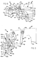
- Figure 1 is a side view of a Variable Camber Kreuger leading edge assembly for an airfoil, in accordance with a preferred embodiment of the present invention, with the leading edge assembly shown in a take-off position;
- Figure 2 is a side view of the leading edge assembly of Figure 1 with the assembly shown in a landing position;
- Figure 3 is a side view of the leading edge assembly of Figure 1 shown in a transition position inbetween the landing and cruise positions;
- Figure 4 is a view of the leading edge assembly of Figure 1 also in a transition position between the cruise and landing positions;
- Figure 5 is a view of the leading edge assembly of Figure 1 in a transition position after just moving out of the cruise position;
- Figure 6 is a side view of the leading edge assembly of Figure 1 in the cruise position retracted within a lower surface of an airfoil;
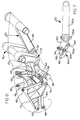
- Figure 7 is a side view of just the lower link;
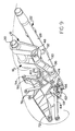
- Figure 8 is a top perspective view of the leading edge assembly in the take-off position, with the panel and bullnose omitted for clarity; and
- Figure 9 is a bottom perspective view of the leading edge assembly of Figure 7.
-
- Referring to Figures 1-6, there is shown a Variable Camber Kreuger (VCK) leading
edge assembly 10 in accordance with a preferred embodiment of the present invention for use with anairfoil 12 of a fixed wing aircraft. Initially, it will be understood that theairfoil 12 includes alower surface 14 having arecess 16 of sufficient area to accommodate theleading edge assembly 10 when the assembly is in a retracted or "cruise" position. - Referring specifically to Figures 1 and 2, the leading
edge assembly 10 is suspended from theairfoil 12 by a forward suspension link 18 pivotably coupled atpoint 20 to theairfoil 12, and anaft suspension link 22 drivingly coupled atupper end 24 to atorque shaft 26a of anactuator 26. Theaft suspension link 22 is comprised of anupper link 28 and alower link 30 pivotably coupled atpoint 32. Alower end 34 of theforward suspension link 18 is pivotably coupled atpoint 36 with a portion of thelower link 30. - The
leading edge assembly 10 also comprises abullnose 38 which is hingedly attached via a hinge atpoint 40 to avariable camber panel 42. Thepanel 42 has a leading,forwardmost edge 42a and a trailingedge 42b.Forwardmost edge 42a abuts against edge 16s to form a seal when thevariable camber panel 42 is in the fully retraced position. Similarly, trailingedge 42b abutsedge 13 to form a seal when thepanel 42 is in the retracted position. This sealing at the forward and rear portions of thepanel 42 is thus accomplished without independent seal members. - With further reference to Figures 1 and 2, a
scissors linkage assembly 44 includes afirst link 46 pivotably coupled to an intermediate point of the forward suspension link 18 atpoint 48, asecond link 50 pivotably coupled atpivot point 54 to a mountingstructure 42c of thepanel 42. A third scissors link 58 is pivotably coupled atpoint 60 to opposite ends of each ofscissors links pivot point 62 to a portion of thelower link 30. Afirst extension link 64 is also pivotably coupled at apoint 66 to thelower link 30 and at an opposite end thereof atpoint 68 to thebullnose 38. -
Link 50 is preferably a two piece link threadably coupled to allow adjustment of its overall length. This degree of adjustability allows a degree of preload to be achieved betweensurface 12a and trailingedge 42b when thepanel 42 is in its cruise position. - The
bullnose 38 is also coupled via ashort link 39 to pivotpoint 70, which is in turn coupled to asecond extension link 72. An opposite end of thesecond extension link 72 is coupled to the mountingstructure 42c atpivot point 54. An intermediate point of thesecond extension link 72 is also pivotably coupled atpoint 74 to thelower link 30. Finally, asupport link 76 is operatively pivotably coupled atpivot point 78 to thelower link 30 and at its opposite end to the mountingstructure 42c viapivot point 80. Accordingly, it will be appreciated that theentire panel 42, bullnose 38 and linkage assembly comprisingscissors linkage assembly 44,support link 76, and the first and second extension links 64 and 72, respectively, are all suspended by theforward suspension link 18 and theaft suspension link 28. - The approximate forwardmost half of the panel 42 (i.e., approximately between pivot points 40 and 80) comprises the variable camber portion of the
panel 42. The approximate rear half of the panel 42 (i.e., the portion approximately between pivot points 80 and 54) represents the rigid portion of thepanel 42. - With brief reference to Figure 7, the
lower link 30 is shown in greater detail. Thislink 30 is formed with an extending link 30a pivotally mounted atpoint 30b to ayoke assembly 30c. Theyoke assembly 30c is in turn secured by abolt 30d to anaft link member 30e. A threadedbolt 30f extends through an opening in aflange 30g of the extending link 30a. By using washers or shims, in connection withbolt 30f, the position ofpivot point 62 can be adjusted to also help control the degree of preload applied throughscissors link 58 between thesurface 12a andaft edge 42b of thepanel 42. - The operation of the
leading edge assembly 10 will now be described. With initial reference to Figure 6, the leadingedge assembly 10 is shown in the retracted or "cruise" position. In this position theairfoil 12 forms a highly aerodynamic shape suitable for high speed flight andpanel 42 has a first degree of curvature. Thebullnose 38 is folded within therecess 16 andpanel 42 forms a smooth, integral portion of thelower surface 14 of theairfoil 12. - Referring now to Figure 5, when the
leading edge assembly 10 is to be urged to either a "take-off' or "landing" position, thetorque shaft 26a of theactuator 26 is rotated which causes theupper link 28 of theaft suspension link 22 to be rotated clockwise in the drawing of Figure 5. This clockwise rotation causes thepanel 42 to be rotated more rapidly at theleading edge 42a than at the trailingedge 42b. The trailingedge 42b also remains relatively close to the bottom,forwardmost edge 12a of theairfoil 12 to thus inhibit airflow into therecess 16 of theairfoil 12. - Referring to Figure 4, further clockwise rotation of the
upper link 22 by theactuator 26 causes thelower link 30 to descend, which also causes the forward suspension link 18 to rotate clockwise. Thefirst extension link 64 also causes clockwise rotational movement of thebullnose 38 aboutpivot point 40. - Referring to Figure 3, further clockwise rotation of the
upper link 28 causes thefirst extension link 64 to continue rotating thebullnose 38 aboutpivot point 68. Thescissors linkage assembly 44 also operates to begin bending thepanel 42 via a pulling action by thethird link 58 as thelower link 30 extends further forwardly of theairfoil 12. - Referring to Figure 2, still further clockwise movement of the
upper link 28 causes thefirst extension link 64 to urge thebullnose 38 rotationally into its fully extended (i.e., landing) position. In this position, a trailingedge 38a of thebullnose 38 is disposed slightly underneath theleading edge 42a of thepanel 42 to provide a smooth, aerodynamic seal therebetween. Thethird link 58 of thescissors linkage assembly 44 also causes a slight additional degree of curving of thepanel 42 such that thepanel 42 forms a desired aerodynamic curvature, or second degree of curvature, during landing operations. In this position a "gap" is present between the trailingedge 42b of thepanel 42 and an upper,forwardmost edge 12b of theairfoil 12. - An important advantage of the present invention is that the
panel 42 is moved from the positions of Figures 3 and 4 into the position shown in Figure 2 without presenting thepanel 42 in a position where it operates to scoop air into therecess 16. In this manner the aerodynamic efficiency of theairfoil 12 during deployment is improved significantly. - Referring now to Figure 1, further clockwise rotation of the
upper link 28 causes the trailingedge 42b of thepanel 42 to abut the upper,forwardmost edge 12b of theairfoil 12 to form a relatively smooth, aerodynamic seal therebetween. Advantageously, this seal is formed without any separate sealing member or component being required at this interface. Theleading edge assembly 10 is also shown in the take-off position in Figures 8 and 9, with thebullnose 38 andpanel 42 omitted for clarity. In these views it can be seen that a pair of j-links 76, a pair ofsecond links 50, a pair offirst links 46, and a pair of forward suspension links 18 are employed to form theleading edge mechanism 10. - Another advantage of the present invention is that the
scissors linkage assembly 44 allows very good control of the position, angle and shape of thepanel 42 of theassembly 10. Thescissors assembly 44 also provides for quick auto-gapping of theleading edge assembly 10 if stall is imminent. - When the
leading edge assembly 10 is in the take-off position shown in Figure 1, theupper link 28,lower link 30 andfirst extension link 64 form a relatively straight, truss-type load path. As a result, a lesser degree of torque is required to hold theassembly 10 in this position than with many previously developed leading edge constructions. This also provides an extremely structurally rigid arrangement. - Another advantage of the
leading edge assembly 10 of the present invention is that if theassembly 10 is overloaded when in the landing or take-off positions, theassembly 10 will collapse, thus avoiding damage to surrounding structure of theairfoil 12. This also ensures that theleading edge assembly 10 remains attached to theairfoil 12 in the event that unusually high aerodynamic forces are experienced which cause overloading of theleading edge assembly 10. - Still further, the overlapping of the forwardmost
leading edge 42a of thepanel 42 over thebullnose 38 when theassembly 10 is urged into the landing or take-off positions eliminates the need for separate seals to be used at the panel/bullnose interface for landing and take-off, as well as eliminating the need for separate seals at the panel/airfoil interface when in the take-off position. This also serves to reduce weight, the number of parts required for theassembly 10, and thus the cost and complexity of the assembly. - Those skilled in the art can now appreciate from the foregoing description that the broad teachings of the present invention can be implemented in a variety of forms. Therefore, while this invention has been described in connection with particular examples thereof, the true scope of the invention should not be so limited since other modifications will become apparent to the skilled practitioner upon a study of the drawings, specification and following claims.
Claims (13)
- A variable camber leading edge assembly for an airfoil, comprising:wherein said bullnose and said variable camber panel are urged rotationally from a cruise position, wherein said bullnose and said variable camber panel are retracted within a lower area of said airfoil to form a lower surface of said airfoil, to a landing position, wherein said variable camber panel and said bullnose are rotated to extend forwardly of said airfoil without causing a scooping of air into said lower area and to form a gap between said variable camber panel and a forwardmost upper edge surface of said airfoil;A forward suspension link pivotably coupled at a first end to a portion of said airfoil;an aft suspension link coupled at a first end to a portion of said airfoil aft of said first end of said forward suspension link;a bullnose;a variable camber panel hingedly coupled at a first end to said bullnose;a linkage assembly operably supporting said bullnose and said variable camber panel from said forward and aft suspension links;
wherein said bullnose and variable camber panel are moveable rotationally from said cruise position to a take-off position without scooping air into said lower area of said airfoil, and wherein said variable camber panel forms a smooth, gapless engagement with said forwardmost upper edge surface of said airfoil; and
and wherein said linkage assembly operates to alter a curvature of said variable camber panel when said leading edge assembly is moved between said cruise and said takeoff and landing positions. - The leading edge assembly of claim 1, wherein said linkage assembly comprises a scissors linkage assembly operatively coupled to said variable camber panel, to said aft suspension link and to said forward suspension link.
- The leading edge assembly of claim 2, wherein said scissors linkage assembly comprises first, second and third scissors links pivotably coupled to one another at a common pivot point.
- The leading edge assembly of claim 1, wherein in said cruise position said variable camber panel forms seals at a trailing edge and at a leading edge with respect to said airfoil.
- The leading edge assembly of claim 1, wherein said linkage assembly comprises first and second extension links, each of said extension links being coupled at one end thereof to portions of said bullnose and at opposite ends thereof to said variable camber panel and said aft suspension link.
- A variable camber leading edge assembly for an airfoil, comprising:wherein said bullnose and said variable camber panel are movable by rotational movement of said aft support link from a cruise position retracted within a lower surface of said airfoil to a landing position, wherein in said landing position said second end of said variable camber panel is spaced apart from a leading edge of said airfoil to form a gap therebetween, and when in said cruise position said variable camber panel forms a first arc;a forward suspension link pivotably coupled at a first end to a portion of said airfoil;an aft suspension link coupled at a first end to a portion of said airfoil aft of said first end of said forward suspension link;a bullnose;a variable camber panel hingedly coupled at a first end to said bullnose;a first extension link coupled at a first end to said bullnose and at a second end to said aft suspension link;a support link fixedly secured adjacent a trailing edge of said variable camber panel;a second extension link coupled at a first end to said bullnose and at a second end to said support link, and at an intermediate point to said aft suspension link;a scissors linkage assembly having:a first scissors link pivotably coupled at a first point to an intermediate point of said forward suspension link;a second scissors link pivotably coupled at a first point to said support link;and a third scissors link pivotably coupled at a first end to second ends of each of said first and second scissors links, and at a second end thereof pivotably to a second end of said aft suspension link;
wherein said variable camber panel is moveable from said cruise position to a takeoff position extending forwardly of said airfoil, wherein said scissors linkage operates to flex said variable camber panel to form a second arc and wherein said second end of said variable camber panel engages flush with said leading edge of said airfoil to form a smooth, aerodynamic transition therebetween; and
wherein retracting movement of said variable camber panel from said takeoff position to said cruise position is accomplished by rotating said variable camber panel and said bullnose attached thereto about a lower end of said forward main support link such that said variable camber panel and said bullnose do not operate to scoop air into a lower area of said airfoil when moving from said takeoff position to said cruise position. - The leading edge assembly of claim 6, wherein said aft support link comprises an upper link and a lower link pivotably coupled to one another.
- The leading edge assembly of claim 6, wherein said first extension link causes said bullnose to be folded toward said variable camber panel as said leading edge assembly is retracted into said lower area of said airfoil when moving into said cruise position.
- The leading edge assembly of claim 6, wherein in said takeoff position, said aft support link and said first extension link form a generally straight length to provide a truss-type load path.
- The leading edge assembly of claim 6, wherein said second arc is greater than said first arc.
- A variable camber leading edge assembly for an airfoil, comprising:wherein said bullnose and said variable camber panel are movable by rotational movement of said aft support link by said actuator from a cruise position, wherein said variable camber panel assumes a first arc, from within a lower surface of said airfoil to a landing position, wherein in said landing position said second end of said variable camber panel is spaced apart from a leading edge of said airfoil to form a gap therebetween, and said variable camber panel forms a second arc;an aft suspension link assembly having an upper link and a lower link pivotably coupled together, wherein said upper link thereof is pivotably coupled at a first end thereof to a portion of said airfoil;a forward suspension link pivotably coupled at a first end to a portion of said airfoil forward of said first end of said aft suspension link;an actuator having a torque shaft operably coupled to said first end of said upper link of said aft suspension link;a bullnose;a variable camber panel hingedly coupled at a first end to said bullnose;a first extension link coupled at a first end to said bullnose and at a second end to said lower link of said aft suspension link;a second extension link coupled at a first end to said bullnose and operatively coupled at a second end thereof to a second end of said variable camber panel, and at an intermediate point to said lower link of said aft suspension link;a scissors linkage assembly having:a first scissors link pivotably coupled at a first point to an intermediate point of said forward suspension link;a second scissors link pivotably coupled at a first point to said second end of said variable camber panel;and a third scissors link pivotably coupled at a first end to second ends of each of said first and second scissors links, and at a second end thereof pivotably to said second end of said aft suspension link; and
wherein said variable camber panel is moveable from said cruise position to a takeoff position extending forwardly of said airfoil, wherein said scissors linkage assembly operates to flex said variable camber panel to form said second arc and wherein said second end of said variable camber panel engages flush with said leading edge of said airfoil to form a smooth, aerodynamic transition therebetween, and wherein said second arc is greater than said first arc; and
wherein retracting movement of said variable camber panel from said takeoff position to said cruise position is accomplished by rotating said variable camber panel and said bullnose attached thereto about a lower end of said forward main support link such that said variable camber panel and said bullnose do not operate to scoop air into a lower area of said airfoil when moving from said takeoff position to said cruise position. - A method of controlling a variable camber panel disposed within a lower area of an airfoil when the panel is in a cruise position such that said panel is extended forwardly of said airfoil into a landing position in a manner to avoid scooping air during movement between said cruise and landing positions, said method comprising the steps of:suspending said variable camber panel from within a recess point disposed within said airfoil by a linkage assembly;using said linkage assembly to cause a forward edge of said variable camber panel to being rotating at a greater rate of travel than a trailing edge of said panel when said panel is moved initially out of said cruise position;using said linkage assembly to continue rotating said variable camber panel while also moving said panel forwardly of said airfoil such that said trailing edge is maintained close to a leading edge surface of said airfoil as said panel is moved to and beyond an intermediate position between said cruise and landing positions; andcontinuing to rotate said variable camber panel beyond said intermediate position to said landing position, wherein said panel forms a relatively continuously curving forward section of said airfoil.
- The method of claim 12, further comprising the step of:continuing to rotate said variable camber panel from said landing position to a takeoff position, wherein said trailing edge of said panel abuts said leading edge surface of said airfoil to form a gapless, continuously curving extension of said airfoil.
Applications Claiming Priority (2)
| Application Number | Priority Date | Filing Date | Title |
|---|---|---|---|
| US714026 | 1996-09-11 | ||
| US09/714,026 US6375126B1 (en) | 2000-11-16 | 2000-11-16 | Variable camber leading edge for an airfoil |
Publications (3)
| Publication Number | Publication Date |
|---|---|
| EP1207101A2 true EP1207101A2 (en) | 2002-05-22 |
| EP1207101A3 EP1207101A3 (en) | 2003-06-04 |
| EP1207101B1 EP1207101B1 (en) | 2006-09-13 |
Family
ID=24868498
Family Applications (1)
| Application Number | Title | Priority Date | Filing Date |
|---|---|---|---|
| EP01203799A Expired - Lifetime EP1207101B1 (en) | 2000-11-16 | 2001-10-08 | Variable camber leading edge for an airfoil |
Country Status (3)
| Country | Link |
|---|---|
| US (1) | US6375126B1 (en) |
| EP (1) | EP1207101B1 (en) |
| DE (1) | DE60122996T2 (en) |
Families Citing this family (60)
| Publication number | Priority date | Publication date | Assignee | Title |
|---|---|---|---|---|
| DE69718659T2 (en) | 1996-10-22 | 2003-05-22 | The Boeing Co., Seattle | PLANE WITH UNARROWED SLOT WING FOR TRAVEL FLIGHT |
| US7258308B2 (en) * | 2002-07-02 | 2007-08-21 | The Boeing Company | Method and apparatus for controlling airflow with a gapped trailing edge device having a flexible flow surface |
| US7059563B2 (en) * | 2003-06-03 | 2006-06-13 | The Boeing Company | Systems, apparatuses, and methods for moving aircraft control surfaces |
| US7243881B2 (en) * | 2003-06-03 | 2007-07-17 | The Boeing Company | Multi-function trailing edge devices and associated methods |
| US6910327B2 (en) * | 2003-07-28 | 2005-06-28 | The Boeing Company | Apparatus and methods for varying inlet lip geometry of a jet engine inlet |
| US6799739B1 (en) | 2003-11-24 | 2004-10-05 | The Boeing Company | Aircraft control surface drive system and associated methods |
| US7424350B2 (en) | 2004-02-02 | 2008-09-09 | The Boeing Company | Vehicle control systems and corresponding sizing methods |
| US7357358B2 (en) | 2004-02-27 | 2008-04-15 | The Boeing Company | Aircraft leading edge device systems and corresponding sizing methods |
| US7270305B2 (en) * | 2004-06-15 | 2007-09-18 | The Boeing Company | Aircraft leading edge apparatuses and corresponding methods |
| US6978971B1 (en) * | 2004-06-15 | 2005-12-27 | The Boeing Company | Methods and apparatuses for controlling airflow proximate to engine/airfoil systems |
| US7494094B2 (en) * | 2004-09-08 | 2009-02-24 | The Boeing Company | Aircraft wing systems for providing differential motion to deployable lift devices |
| US7264206B2 (en) | 2004-09-30 | 2007-09-04 | The Boeing Company | Leading edge flap apparatuses and associated methods |
| US7322547B2 (en) * | 2005-01-31 | 2008-01-29 | The Boeing Company | Aerospace vehicle leading edge slat devices and corresponding methods |
| US7338018B2 (en) | 2005-02-04 | 2008-03-04 | The Boeing Company | Systems and methods for controlling aircraft flaps and spoilers |
| US7246770B2 (en) * | 2005-02-25 | 2007-07-24 | Northrop Grumman Corporation | Aircraft with rotatable leading edge of fuselage and wings |
| US7216835B2 (en) * | 2005-02-25 | 2007-05-15 | Northrop Grumman Corporation | Aircraft with extendable leading edge of fuselage and wings |
| US7204454B2 (en) * | 2005-02-25 | 2007-04-17 | Northrop Grumman Corporation | Aircraft with articulated leading edge of fuselage and wings |
| US7309043B2 (en) * | 2005-04-27 | 2007-12-18 | The Boeing Company | Actuation device positioning systems and associated methods, including aircraft spoiler droop systems |
| US7721999B2 (en) * | 2005-05-20 | 2010-05-25 | The Boeing Company | Aerospace vehicle fairing systems and associated methods |
| US7300021B2 (en) * | 2005-05-20 | 2007-11-27 | The Boeing Company | Aerospace vehicle fairing systems and associated methods |
| US7367530B2 (en) * | 2005-06-21 | 2008-05-06 | The Boeing Company | Aerospace vehicle yaw generating systems and associated methods |
| DE102005031840B4 (en) * | 2005-07-06 | 2013-11-14 | Airbus Operations Gmbh | Driving and guiding device for a valve arranged on an aircraft wing |
| US7500641B2 (en) | 2005-08-10 | 2009-03-10 | The Boeing Company | Aerospace vehicle flow body systems and associated methods |
| US7611099B2 (en) | 2005-09-07 | 2009-11-03 | The Boeing Company | Seal assemblies for use with drooped spoilers and other control surfaces on aircraft |
| US7708231B2 (en) | 2005-11-21 | 2010-05-04 | The Boeing Company | Aircraft trailing edge devices, including devices having forwardly positioned hinge lines, and associated methods |
| US7475854B2 (en) | 2005-11-21 | 2009-01-13 | The Boeing Company | Aircraft trailing edge devices, including devices with non-parallel motion paths, and associated methods |
| US7618086B2 (en) | 2005-12-01 | 2009-11-17 | Thomas Scott Breidenbach | Aerodynamic drag reducing apparatus |
| US7578484B2 (en) | 2006-06-14 | 2009-08-25 | The Boeing Company | Link mechanisms for gapped rigid krueger flaps, and associated systems and methods |
| DE102006030315A1 (en) * | 2006-06-30 | 2008-01-17 | Airbus Deutschland Gmbh | High-lift system on the wing of an aircraft |
| GB0700604D0 (en) * | 2007-01-11 | 2007-02-21 | Airbus Uk Ltd | A leading edge structure for an aerofoil |
| US8360509B2 (en) | 2007-05-17 | 2013-01-29 | Advanced Transit Dynamics, Inc. | Rear-mounted aerodynamic structure for truck cargo bodies |
| US8100461B2 (en) | 2007-05-17 | 2012-01-24 | Advanced Transit Dynamics, Inc. | Rear-mounted aerodynamic structure for truck cargo bodies |
| US8439644B2 (en) * | 2007-12-10 | 2013-05-14 | United Technologies Corporation | Airfoil leading edge shape tailoring to reduce heat load |
| US7954769B2 (en) | 2007-12-10 | 2011-06-07 | The Boeing Company | Deployable aerodynamic devices with reduced actuator loads, and related systems and methods |
| US7766282B2 (en) | 2007-12-11 | 2010-08-03 | The Boeing Company | Trailing edge device catchers and associated systems and methods |
| US7857376B2 (en) * | 2008-02-21 | 2010-12-28 | Adaptive Aerodynamic, Llc | Aerodynamic drag reducing apparatus |
| US8226048B2 (en) * | 2008-12-09 | 2012-07-24 | The Boeing Company | Link mechanisms, including Stephenson II link mechanisms for multi-position flaps and associated systems and methods |
| US8382045B2 (en) | 2009-07-21 | 2013-02-26 | The Boeing Company | Shape-changing control surface |
| DE102009057340A1 (en) | 2009-12-07 | 2011-06-09 | Airbus Operations Gmbh | High lift system for an aircraft, method of moving a lift flap, and aircraft with a high lift system |
| DE102010014792A1 (en) * | 2010-04-13 | 2011-10-13 | Airbus Operations Gmbh | High-lift system for an aircraft |
| DE102011018906A1 (en) * | 2011-04-28 | 2012-10-31 | Airbus Operations Gmbh | High lift system for an aircraft and method for influencing the high lift characteristics of an aircraft |
| US20130076064A1 (en) | 2011-09-20 | 2013-03-28 | Advanced Transit Dynamics, Inc. | Rear-mounted retractable aerodynamic structure for cargo bodies |
| US9440689B1 (en) | 2011-09-20 | 2016-09-13 | Stemco Lp | Aerodynamic structures secured to the underbody of cargo bodies |
| US20130106136A1 (en) | 2011-10-27 | 2013-05-02 | Advanced Transit Dynamics, Inc. | Rear-mounted aerodynamic structures for cargo bodies |
| US8925870B1 (en) | 2012-03-09 | 2015-01-06 | The Boeing Company | Morphing wing leading edge |
| BR112015000663A2 (en) | 2012-07-11 | 2017-06-27 | Advanced Transit Dynamics Inc | retractable aerodynamic structures for loading bodies and methods for controlling their positioning |
| US9365284B2 (en) * | 2013-04-22 | 2016-06-14 | The Boeing Company | High-positioned 2-position variable camber Krueger |
| US9598167B2 (en) | 2014-03-04 | 2017-03-21 | The Boeing Company | Morphing airfoil leading edge |
| US9415856B2 (en) | 2014-06-04 | 2016-08-16 | The Boeing Company | Dual-rib morphing leading edge |
| EP3241740B1 (en) * | 2016-05-03 | 2020-08-19 | Airbus Operations GmbH | System for driving a slat device of an aircraft wing |
| EP3269635A1 (en) * | 2016-07-12 | 2018-01-17 | The Aircraft Performance Company UG | Airplane wing |
| US10829198B2 (en) | 2017-06-21 | 2020-11-10 | The Boeing Company | Krueger flap apparatus and methods incorporating a bullnose having a contour variation along a spanwise direction |
| CN110891857B (en) | 2017-07-12 | 2023-07-11 | 航空器性能公司 | aircraft wing having at least two winglets |
| GB2569376A (en) * | 2017-12-15 | 2019-06-19 | Airbus Operations Ltd | 4-bar linkage |
| ES2819559T3 (en) | 2017-12-15 | 2021-04-16 | The Aircraft Performance Company Gmbh | Airplane wing |
| EP3511243B1 (en) * | 2018-01-15 | 2021-12-29 | The Aircraft Performance Company GmbH | Airplane wing |
| GB2616252A (en) * | 2022-01-31 | 2023-09-06 | Airbus Operations Ltd | Aircraft with movable wing tip device |
| GB2615311A (en) * | 2022-01-31 | 2023-08-09 | Airbus Operations Ltd | Aircraft wing with movable wing tip device |
| US12030647B2 (en) * | 2022-02-18 | 2024-07-09 | The Boeing Company | Thermal anti-ice bypass systems for use with aircraft |
| GB2628523B (en) * | 2022-11-16 | 2025-07-09 | Airbus Operations Ltd | Aircraft wing |
Family Cites Families (15)
| Publication number | Priority date | Publication date | Assignee | Title |
|---|---|---|---|---|
| US3504870A (en) | 1967-12-08 | 1970-04-07 | Boeing Co | Aircraft wing variable camber leading edge flap |
| US3556439A (en) | 1968-11-22 | 1971-01-19 | Boeing Co | Methods and high lift systems for making an aircraft wing more efficient for takeoffs and landings |
| US3743219A (en) | 1971-06-30 | 1973-07-03 | Boeing Co | High lift leading edge device |
| FR2249804B1 (en) * | 1973-11-06 | 1976-10-01 | Aerospatiale | |
| US3910530A (en) | 1973-11-07 | 1975-10-07 | Boeing Co | Leading edge flap |
| US3994451A (en) | 1974-03-28 | 1976-11-30 | The Boeing Company | Variable camber airfoil |
| US3941334A (en) | 1975-03-28 | 1976-03-02 | The Boeing Company | Variable camber airfoil |
| US4042191A (en) * | 1976-05-03 | 1977-08-16 | The Boeing Company | Slot seal for leading edge flap |
| US4159089A (en) * | 1977-05-31 | 1979-06-26 | Boeing Commercial Airplane Company | Variable camber flap |
| US4189120A (en) | 1977-12-14 | 1980-02-19 | Boeing Commercial Airplane Company | Variable camber leading edge flap |
| US4189121A (en) | 1978-01-23 | 1980-02-19 | Boeing Commercial Airplane Company | Variable twist leading edge flap |
| US4262868A (en) | 1979-05-29 | 1981-04-21 | The Boeing Company | Three-position variable camber flap |
| US4351502A (en) | 1980-05-21 | 1982-09-28 | The Boeing Company | Continuous skin, variable camber airfoil edge actuating mechanism |
| US4445655A (en) * | 1982-02-01 | 1984-05-01 | Omac, Inc. | Kreuger flap actuating mechanism for delta wing, canard type aircraft |
| US5158252A (en) | 1991-10-24 | 1992-10-27 | The Boeing Company | Three-position variable camber Krueger leading edge flap |
-
2000
- 2000-11-16 US US09/714,026 patent/US6375126B1/en not_active Expired - Lifetime
-
2001
- 2001-10-08 DE DE60122996T patent/DE60122996T2/en not_active Expired - Lifetime
- 2001-10-08 EP EP01203799A patent/EP1207101B1/en not_active Expired - Lifetime
Non-Patent Citations (1)
| Title |
|---|
| None |
Also Published As
| Publication number | Publication date |
|---|---|
| DE60122996T2 (en) | 2007-06-06 |
| EP1207101A3 (en) | 2003-06-04 |
| US6375126B1 (en) | 2002-04-23 |
| EP1207101B1 (en) | 2006-09-13 |
| DE60122996D1 (en) | 2006-10-26 |
Similar Documents
| Publication | Publication Date | Title |
|---|---|---|
| US6375126B1 (en) | Variable camber leading edge for an airfoil | |
| RU2464202C2 (en) | Aerofil section leading edge | |
| US5836550A (en) | Mechanism for streamwise fowler deployment of the wing trailing or leading edge | |
| EP2032434B1 (en) | Link mechanisms for gapped rigid krueger flaps, and associated systems and methods | |
| RU2695253C1 (en) | Rear wing of vehicle with adjustable cross-section and pull-out flap (versions) | |
| EP3134314B1 (en) | An aircraft with a foldable wing tip device | |
| US6164599A (en) | Aerofoil profile with variable profile adaptation | |
| US6464176B2 (en) | Flap operating device | |
| EP0538963B1 (en) | Three-position variable camber krueger leading edge flap | |
| US8006940B2 (en) | Method and apparatus for deploying an auxiliary lift foil | |
| US4053124A (en) | Variable camber airfoil | |
| US6164598A (en) | Adaptive control surface apparatus | |
| EP3034392B1 (en) | Cove lip door slaved to trailing edge control device | |
| US9079655B2 (en) | System for increasing controllability for an aircraft | |
| US6010097A (en) | Scissor linkage type slotted flap mechanism | |
| EP0130983A1 (en) | Variable-camber airfoil. | |
| GB2578587A (en) | Aircraft wing tips | |
| CN110871885B (en) | Wing systems for aircraft with fluid bodies and covering panels | |
| CN110294102A (en) | The composite-motion mechanism of integral type flaperon | |
| EP3411294B1 (en) | Folding beam for swinging wing | |
| CN117755480A (en) | Wing components for aircraft and aircraft | |
| CN117465658A (en) | Wings, trailing edge high-lift components and aircraft for aircraft | |
| WO1996009955A1 (en) | Linkage to deploy a surface relative to a wing | |
| GB2572216A (en) | Leading edge flight control surfaces | |
| EP0120013A1 (en) | Folding truss mechanism for trailing edge flaps |
Legal Events
| Date | Code | Title | Description |
|---|---|---|---|
| PUAI | Public reference made under article 153(3) epc to a published international application that has entered the european phase |
Free format text: ORIGINAL CODE: 0009012 |
|
| AX | Request for extension of the european patent |
Free format text: AL;LT;LV;MK;RO;SI |
|
| PUAL | Search report despatched |
Free format text: ORIGINAL CODE: 0009013 |
|
| AK | Designated contracting states |
Designated state(s): AT BE CH CY DE DK ES FI FR GB GR IE IT LI LU MC NL PT SE TR |
|
| AX | Request for extension of the european patent |
Extension state: AL LT LV MK RO SI |
|
| 17P | Request for examination filed |
Effective date: 20030813 |
|
| 17Q | First examination report despatched |
Effective date: 20031120 |
|
| AKX | Designation fees paid |
Designated state(s): DE FR GB |
|
| GRAP | Despatch of communication of intention to grant a patent |
Free format text: ORIGINAL CODE: EPIDOSNIGR1 |
|
| GRAS | Grant fee paid |
Free format text: ORIGINAL CODE: EPIDOSNIGR3 |
|
| GRAA | (expected) grant |
Free format text: ORIGINAL CODE: 0009210 |
|
| AK | Designated contracting states |
Kind code of ref document: B1 Designated state(s): DE FR GB |
|
| REG | Reference to a national code |
Ref country code: GB Ref legal event code: FG4D |
|
| REF | Corresponds to: |
Ref document number: 60122996 Country of ref document: DE Date of ref document: 20061026 Kind code of ref document: P |
|
| ET | Fr: translation filed | ||
| PLBI | Opposition filed |
Free format text: ORIGINAL CODE: 0009260 |
|
| PLAB | Opposition data, opponent's data or that of the opponent's representative modified |
Free format text: ORIGINAL CODE: 0009299OPPO |
|
| 26 | Opposition filed |
Opponent name: AIRBUS SAS/AIRBUS FRANCE SAS/AIRBUS UK LIMITED/ AI Effective date: 20070613 |
|
| PLAX | Notice of opposition and request to file observation + time limit sent |
Free format text: ORIGINAL CODE: EPIDOSNOBS2 |
|
| R26 | Opposition filed (corrected) |
Opponent name: AIRBUS SAS/AIRBUS FRANCE SAS/AIRBUS UK LIMITED/ AI Effective date: 20070613 |
|
| PLBB | Reply of patent proprietor to notice(s) of opposition received |
Free format text: ORIGINAL CODE: EPIDOSNOBS3 |
|
| PLCK | Communication despatched that opposition was rejected |
Free format text: ORIGINAL CODE: EPIDOSNREJ1 |
|
| PLBN | Opposition rejected |
Free format text: ORIGINAL CODE: 0009273 |
|
| STAA | Information on the status of an ep patent application or granted ep patent |
Free format text: STATUS: OPPOSITION REJECTED |
|
| 27O | Opposition rejected |
Effective date: 20101122 |
|
| REG | Reference to a national code |
Ref country code: FR Ref legal event code: PLFP Year of fee payment: 15 |
|
| REG | Reference to a national code |
Ref country code: FR Ref legal event code: PLFP Year of fee payment: 16 |
|
| REG | Reference to a national code |
Ref country code: FR Ref legal event code: PLFP Year of fee payment: 17 |
|
| REG | Reference to a national code |
Ref country code: FR Ref legal event code: PLFP Year of fee payment: 18 |
|
| PGFP | Annual fee paid to national office [announced via postgrant information from national office to epo] |
Ref country code: DE Payment date: 20201028 Year of fee payment: 20 Ref country code: FR Payment date: 20201026 Year of fee payment: 20 Ref country code: GB Payment date: 20201027 Year of fee payment: 20 |
|
| REG | Reference to a national code |
Ref country code: DE Ref legal event code: R071 Ref document number: 60122996 Country of ref document: DE |
|
| REG | Reference to a national code |
Ref country code: GB Ref legal event code: PE20 Expiry date: 20211007 |
|
| PG25 | Lapsed in a contracting state [announced via postgrant information from national office to epo] |
Ref country code: GB Free format text: LAPSE BECAUSE OF EXPIRATION OF PROTECTION Effective date: 20211007 |