EP1207099A2 - Biped ambulatory robot - Google Patents
Biped ambulatory robot Download PDFInfo
- Publication number
- EP1207099A2 EP1207099A2 EP01309660A EP01309660A EP1207099A2 EP 1207099 A2 EP1207099 A2 EP 1207099A2 EP 01309660 A EP01309660 A EP 01309660A EP 01309660 A EP01309660 A EP 01309660A EP 1207099 A2 EP1207099 A2 EP 1207099A2
- Authority
- EP
- European Patent Office
- Prior art keywords
- robot
- storage device
- electrical storage
- posture
- gravity
- Prior art date
- Legal status (The legal status is an assumption and is not a legal conclusion. Google has not performed a legal analysis and makes no representation as to the accuracy of the status listed.)
- Granted
Links
- 210000002414 leg Anatomy 0.000 claims abstract description 49
- 230000005484 gravity Effects 0.000 claims abstract description 34
- 210000000629 knee joint Anatomy 0.000 claims abstract description 29
- 238000009434 installation Methods 0.000 claims description 9
- 238000012423 maintenance Methods 0.000 abstract 1
- 230000003187 abdominal effect Effects 0.000 description 46
- 210000001503 joint Anatomy 0.000 description 10
- 210000000689 upper leg Anatomy 0.000 description 5
- 210000003423 ankle Anatomy 0.000 description 3
- 238000011105 stabilization Methods 0.000 description 3
- 210000000544 articulatio talocruralis Anatomy 0.000 description 2
- 239000003990 capacitor Substances 0.000 description 2
- 210000002683 foot Anatomy 0.000 description 2
- 230000006641 stabilisation Effects 0.000 description 2
- HBBGRARXTFLTSG-UHFFFAOYSA-N Lithium ion Chemical compound [Li+] HBBGRARXTFLTSG-UHFFFAOYSA-N 0.000 description 1
- 210000001015 abdomen Anatomy 0.000 description 1
- 238000010276 construction Methods 0.000 description 1
- 230000000694 effects Effects 0.000 description 1
- 210000002310 elbow joint Anatomy 0.000 description 1
- 230000005611 electricity Effects 0.000 description 1
- 239000000284 extract Substances 0.000 description 1
- 230000006870 function Effects 0.000 description 1
- 229910001416 lithium ion Inorganic materials 0.000 description 1
- 238000000034 method Methods 0.000 description 1
- 238000000926 separation method Methods 0.000 description 1
- 230000035939 shock Effects 0.000 description 1
- 210000000323 shoulder joint Anatomy 0.000 description 1
- 230000016776 visual perception Effects 0.000 description 1
- 210000003857 wrist joint Anatomy 0.000 description 1
Images


Classifications
-
- B—PERFORMING OPERATIONS; TRANSPORTING
- B25—HAND TOOLS; PORTABLE POWER-DRIVEN TOOLS; MANIPULATORS
- B25J—MANIPULATORS; CHAMBERS PROVIDED WITH MANIPULATION DEVICES
- B25J19/00—Accessories fitted to manipulators, e.g. for monitoring, for viewing; Safety devices combined with or specially adapted for use in connection with manipulators
- B25J19/005—Accessories fitted to manipulators, e.g. for monitoring, for viewing; Safety devices combined with or specially adapted for use in connection with manipulators using batteries, e.g. as a back-up power source
-
- B—PERFORMING OPERATIONS; TRANSPORTING
- B62—LAND VEHICLES FOR TRAVELLING OTHERWISE THAN ON RAILS
- B62D—MOTOR VEHICLES; TRAILERS
- B62D57/00—Vehicles characterised by having other propulsion or other ground- engaging means than wheels or endless track, alone or in addition to wheels or endless track
- B62D57/02—Vehicles characterised by having other propulsion or other ground- engaging means than wheels or endless track, alone or in addition to wheels or endless track with ground-engaging propulsion means, e.g. walking members
- B62D57/032—Vehicles characterised by having other propulsion or other ground- engaging means than wheels or endless track, alone or in addition to wheels or endless track with ground-engaging propulsion means, e.g. walking members with alternately or sequentially lifted supporting base and legs; with alternately or sequentially lifted feet or skid
Definitions
- This invention relates to a biped ambulatory robot.
- biped ambulatory robots which the inventors and others have striven to put into practical use in recent years are, in essence, humanoid robots; in well-known biped ambulatory robots, similarly to humans, two leg members are provided extending from a hip portion at the lower end of an upper body or torso, and two arm members are provided extending from shoulder portions on the right and left sides of the torso.
- the operation power to operate the leg members, arm members or the like can also be supplied to the robot from outside via a cable.
- the operable range of such a robot is limited, and cable handling becomes complicated. Consequently, it is preferable that the robot itself be equipped with a battery or other electrical storage device as a power supply for operation.
- an electrical storage device is provided to the robot as the power supply for operation of the robot, an electrical storage device of comparatively large capacity is necessary in order to secure sufficient continuous operating time, so that the electrical storage device is comparatively large and heavy.
- the above electrical storage device is generally mounted on the torso of the robot.
- the torso, including the electrical storage device, of a biped ambulatory robot with such an electrical storage device mounted on the torso is heavy, and when the robot is standing on the floor in a substantially vertically erect posture, a load tends to act on the joints of the leg members supporting the torso.
- the knee joints of both leg members be bent slightly in the forward direction, in this case, if the mounted location of the electrical storage equipment on the torso of the robot is inappropriate, then a large load tends to act on the knee joints of the leg members (a large torque acts on the knee joints from the torso of the robot).
- the capacity of the actuators (electric motors) for the knee joints must be increased, but the knee joint actuators tend to be constrained by structure and size parameters, and it is difficult to greatly increase the capacity.
- a biped ambulatory robot tends to easily lose stability of posture upon receiving an external disturbance or other influence.
- This invention was devised in light of the above considerations, and has as an object the provision of a biped ambulatory robot having an electrical storage device placement structure which reduces the load on the joints (particularly the knee joints) of the robot leg members, and enables the easy securing of stability of the robot posture.
- Another object of this invention is to provide a biped ambulatory robot enabling easy attachment to and detachment from the robot of the electrical storage device.
- the biped ambulatory robot of this invention comprises an electrical storage device as a power supply for robot operation and two leg members, and which stands on a floor on a standing posture in which a knee joint in the middle portion of each of the leg members is bent further in the forward direction from the robot than in a vertically-erect posture in which each of the leg members is extended in the vertical direction, wherein said electrical storage device is mounted in an electrical storage device unit provided on the torso of said robot, such that the center of gravity of said electrical storage device exists at a position further forward than the center of gravity of the robot without said electrical storage device in the vertically-erect posture, and the center of gravity of the robot with the electrical storage device thus mounted in the standing posture exists substantially directly above the knee joint of each of the leg members, as seen from one side of the robot.
- the vertically-erect posture of the robot means the posture in which the two leg members of the robot are extended in the vertical direction, and the entire robot is extended in the vertical direction.
- the above standing posture is the same posture as the above vertically-erect posture for each of the components of the robot other than the two leg members (torso, arm members, or the like).
- the anteroposterior direction of the robot is the direction perpendicular to both the direction in which the two leg members of the robot are aligned while the robot is in the vertically-erect posture (the robot lateral direction), and to the vertical direction.
- the center of gravity of the above electrical storage device in the state in which the electrical storage device is mounted in the above electrical storage device unit, exists in a position which is further forward than the center of gravity of the robot in the case where the robot is in the vertically-erect posture and the electrical storage device is removed, when the robot is viewed from one side (when the robot is viewed from a lateral direction) in the above standing posture with the knee joints of the two leg members of the robot bent somewhat toward the front compared with the vertically-erect posture, the center of gravity of the entire robot, including the above electrical storage device, can be made to exist in a position which is substantially directly above the knee joints of the two leg members of the robot.
- the above standing posture as the basic posture when the robot is standing normally on a floor, the torque acting on the knee joint of each leg member from the upper side of the robot is comparatively small, and the load acting on the knee joints can be lightened.
- control is generally exercised to stabilize the posture of biped ambulatory robots based on an inverted-pendulum dynamic model such as that disclosed for example in Japanese Patent Laid-open No. 5-337849 or in U.S. Patent No. 5,459,659.
- This posture-stabilization control uses the behavior of an inverted pendulum in a pseudo-representation of the behavior characteristics of perturbations in the upper-body position of the robot, to control the torque about the ankles of the robot.
- a torque which causes the robot to lean forward somewhat acts from the upper-body side about the ankles of both leg members of the robot In the case of the biped ambulatory robot of this invention, the center of gravity of the entire robot as seen from one side of the robot is positioned substantially directly above the knee joints of the leg members, bent in the forward direction, so that such a torque can be made to act about the ankles from the torso. As a result, stability of the standing posture of the robot can be easily secured.
- the load acting on by the knee joints of the robot leg members when the robot is in a posture of standing on a floor can be lightened, and in addition, stability of the robot posture can be easily secured.
- this invention is especially preferable for biped ambulatory robots which perform posture stabilization control based on an inverted-pendulum dynamic model.
- said electrical storage device is mounted in said electrical storage device unit such that said electrical storage device can be installed and removed via an aperture provided in either the front surface or the rear surface of the torso of said robot.
- the electrical storage device can be removed from or mounted in the electrical storage device unit, so that attachment and removal of the electrical storage device can be performed easily without the robot tipping or the like.
- said aperture is provided in the front surface of the torso of said robot, and said electrical storage device unit is provided in a position enabling installation and removal of said electrical storage device via said aperture by operation of arm members extending from the torso of said robot, further comprising auxiliary power supply means, other than the electrical storage device, which supplies power for the robot operation when installing and removing said electrical storage device by operation of the arm members.
- the above electrical storage device can be removed from, or installed in, the electrical storage device unit through operation of the arm members of the above robot itself, while the arm members of the robot are operated through power supplied by the above auxiliary power supply means is being operated. Hence attachment and detachment of the electrical storage device can be easily performed by the robot itself.
- the above auxiliary power supply means may be, for example, an auxiliary electrical storage device (which need not have such large capacity), mounted on the robot in addition to the above electrical storage device.
- the auxiliary power supply means may be a component, provided on the robot exterior, which can be connected by freely attaching to and detaching from a commercial power supply or other external power supply, and which receives operating power from the external power supply (specifically, a component comprising a cable for connection to the above external power supply, and a rectifying circuit, voltage regulator circuit or the like).
- an electrical storage device in which an electrical storage device can be freely attached and detached via the above aperture as described above, in a state in which said electrical storage device to said electrical storage device unit releasably, in the state in which the electrical storage device is mounted in the electrical storage device unit.
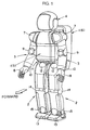
- Fig. 1 is a perspective view showing the entire configuration of the biped ambulatory robot of this embodiment
- Fig. 2 is a side view of the robot
- Fig. 3 is a perspective view showing the configuration of the clasping mechanism of the electrical storage device comprised by the robot.
- the robot is a humanoid robot, comprising an upper body or torso 1, a pair of leg members 2, 2, a pair of arm members 3, 3, and a head member 4.
- the torso 1 of this robot comprises a main body 5, from which the leg members 2, 2 and arm members 3, 3 extend, and which supports the head member 4, and a sub-body 6, provided on the rear surface of the main body 5.
- Shoulder portions 7, 7 are formed on both the left and right sides of the upper portion of the main body 5, and an arm member 3 extends from a shoulder joint mechanism, not shown, incorporated into each of these shoulder portions 7.
- Each arm member 3 has, between the hand portion 8 and shoulder portion 7, in order from the side of the shoulder portion 7, an elbow joint 9 and a wrist joint 10.
- a hip portion (waist portion) 11 is formed at the lower end of the main body 5; from a pair of thigh joints 12, 12 provided on the right and left sides of this hip portion 11, the respective leg members 2 extend downward.
- Each of the leg members 2 has, between the foot portion 13 and thigh joint 12, in order from the thigh joint 12, a knee joint 14 and an ankle joint 15.
- Each of the joints of the above leg members 2 and arm members 3 is driven by an electric motor, not shown.
- the above head portion 4 is supported by the upper end of the main body 5, and incorporates an image pickup device (not shown) for visual perception by the robot.
- the structure of the above torso 1 is here explained, referring to Fig. 2.
- the main body 5 of the torso 1 incorporates, on the upper side of the above hip portion 11, an abdominal body frame 16 in the portion corresponding to the abdomen of the main body 5, and also incorporates, in the upper portion of the main body 5 (the portion corresponding to the chest), an upper body frame 17, fixed in place above the abdominal body frame 16.
- the main body 5 comprises a plurality of exterior panel members 18, covering the front and side surfaces of these body frames 16, 17, and installed on the body frames 16, 17.
- the abdominal body frame 16 is linked to the thigh joints 12 of each leg member 2 via a link mechanism or similar, not shown, incorporated in the hip portion 11 at the lower end of the main body 5.
- the abdominal exterior front panel 18a covering the front surface of the abdominal body frame 16 is mounted in a freely attachable and detachable manner to the abdominal body frame 16 by, for example, installing protruding members provided in the rear face into latching holes provided in the abdominal body frame 16.
- the abdominal exterior front panel 18a can then be removed from the abdominal body frame 16 by moving in the forward direction, as shown by broken lines in Fig. 2.
- an electrical storage device 19 is mounted, in attachable and detachable manner, on the abdominal body frame 16 as the main operating power supply for the robot.
- the above sub-body 6 of the torso 1 incorporates a sub-body frame 20 fixed on the rear surface of the above abdominal body frame 16 and the upper body frame 17.
- a driver circuit unit 21 for an electric motor (not shown) to drive each of the joints of the above leg members 2 and arm members 3 On this sub-body frame 20 are mounted a driver circuit unit 21 for an electric motor (not shown) to drive each of the joints of the above leg members 2 and arm members 3; a control unit 22 (hereafter ECU 22) which handles control of robot operation; a DC/DC converter 23 which converts the voltage level of the above electrical storage device 19 into the level required for operation of electrical motors or the like; and an auxiliary electrical storage device 24 as an auxiliary power supply means to supply power for temporary operation of the robot.
- the sub-body 6 is thus configured.
- the above abdominal body frame 16 of the main body 5 functions as an electrical storage device unit in which the above electrical storage device 19 is mounted, and is formed in a U-shape as seen from one side.
- the electrical storage device 19 is accommodated in the space between an upper horizontal posture frame 16b and a lower horizontal posture frame 16a (hereafter, this space is referred to as the interior space of the abdominal body frame 16), the electrical storage device 19 is supported on the lower horizontal posture frame 16a in a manner enabling free sliding in the anteroposterior direction.
- the aperture 16c in the front end of the abdominal body frame 16 opens toward the front of the robot when the above abdominal exterior front panel 18a is removed, as described above.
- the above electrical storage device 19 is installed, in a manner enabling installation and removal, into the interior space of the abdominal body frame 16, from the above aperture 16c toward the vertical posture frame 16d at the back end of the abdominal body frame 16, and thereby mounted in the abdominal body frame 16.
- a receiving connector 26 is provided, protruding toward the front, on the vertical posture frame 16d on the back end of the abdominal body frame 16, and is connected to the above DC/DC converter 23.
- a power feed connector 27 (connector to output the voltage of the electrical storage device 19), which mates with and can be freely attached to and detached from the receiving connector 26, is provided on the rear surface of the electrical storage device 19. The power feed connector 27 mates with the receiving connector 26 when the electrical storage device 19 is installed into the interior space of the abdominal body frame 16 as described above.
- Plate members 16e are mounted on both the left and right side surfaces of the abdominal body frame 16; the lateral-direction (width direction) position of the electrical storage device is constrained by these plate members 16e.
- the center of gravity of the electrical storage device 19 in the state in which, as described above, the electrical storage device 19 is mounted in the abdominal body frame 16, is for example at point A in Fig. 2 (hereafter, point A is called the electrical storage device center of gravity A).
- point A is called the electrical storage device center of gravity A.
- the abdominal body frame 16 is provided such that the electrical storage device 19 is mounted at a position such that the electrical storage device center of gravity A exists somewhat further forward than the center of gravity B (hereafter called the vertically-erect posture fundamental center of gravity B) when the robot, with electrical storage device 19 excluded, is in the vertically-erect posture.
- the vertically-erect posture fundamental center of gravity B the center of gravity B
- the center of gravity of the entire robot exists between the above electrical storage device center of gravity A and the vertically-erect posture fundamental center of gravity B, at the point C in Fig. 2.
- an abdominal body frame 16 equipped with an electrical storage device 19 is further provided with a clasping mechanism 28 (clasping means) to clasp the electrical storage device 19 at the front end of the lower horizontal posture frame 16a,to the abdominal body frame 16.
- This clasping mechanism 28 may be, for example, configured as shown in Fig. 3. That is, the clasping mechanism 28 comprises a rod 30 provided so as to traverse, in the lateral direction, the cut-out portion 29 formed in the front end of the lower horizontal posture frame 16a of the abdominal body frame 16. The two ends of the rod 30 are installed into the installation holes 31, 31 formed in the lower horizontal posture frame 16a, in a manner enabling free sliding in the lateral direction. Further, the left end of the rod 30 is impelled in the rightward direction by a spring 32 housed in the left-side installation hole 31. In the portion of the rod 30 exposed in the above cut-out portion 29 is formed a clasping pin 33, protruding upward.
- this clasping pin 33 is moved together with the rod 30 to the position indicated by the solid lines in Fig. 3 by the impelling force of the spring 32. At this position, the clasping pin 33 is in contact with the front surface of the electrical storage device 19, and as a result the electrical storage device 19 is clasped such that it cannot be removed from the interior space of the abdominal body frame 16 (below, the position of the clasping pin 33 indicated by solid lines in Fig. 3 is called the clasped position).
- a groove 19a is formed in the lower surface of the electrical storage device 19, extending in the anteroposterior direction from the front edge to the back edge.
- the clasping pin 33 of the above clasping mechanism 28 when moved in opposition to the impelling force of the above spring 32 in the leftward direction to the position indicated by the broken lines in Fig. 3, opposes the groove 19a in such a manner that the upper end of the clasping pin 33 can enter into the groove 19a in the electrical storage device 19 mounted in the abdominal body frame 16.
- the electrical storage device 19 can be installed into and removed from the interior space of the abdominal body frame 16 (hereafter, the position of the clasping pin 33 indicated by the broken lines in Fig. 3 is called the unclasped position) .
- the clasping mechanism 28 comprises a lock pin 34, mounted to enable rotation about the shaft portion 34a on the lower horizontal posture frame 16a facing the above cut-out portion 29.
- the lock pin 34 makes contact with the lower portion of the right-hand surface of the clasping pin 33, as shown by the broken lines in Fig. 3. As a result, the clasping pin 33 is locked together with the rod 30 in the unclasped position by the lock pin 34, opposing the impelling force of the spring 32.
- a clasping mechanism 28 configured in this way, by moving the clasping pin 33 to the unclasped position in opposition to the impelling force of the spring 32 and using the lock pin 34 to lock the clasping pin 33 in the unclasped position, the electrical storage device 19 can be removed from or installed into the interior space of the abdominal body frame 16 in the anteroposterior direction.
- the upper end of the clasping pin 33 moves along the interior of the groove 19a in the electrical storage device 19.
- the clasping pin 33 withdraws from within the groove 19a of the electrical storage device 19.
- the impelling force of the spring 32 causes the clasping pin 33 to move from the unclasped position to the clasped position.
- the clasping pin 33 makes contact with the front surface of the electrical storage device 19, and by this means the electrical storage device 19 is clasped such that removal from the interior space of the abdominal body frame 16 is not possible.
- the clasping pin 33 and lock pin 34 of the clasping mechanism 28 exist in positions which can be reached by the hand portion 8 of each arm member 3 of the above robot in a state in which the abdominal exterior front panel 18a is removed.
- the biped ambulatory robot of this embodiment further comprises, in addition to the above-described configuration, sensors to detect the operating positions (the rotation positions of electric motors driving each joint) of each of the joints of each leg member 2 and arm member 3, sensors to detect the load and torque acting on the foot portion 13 of each leg member 2 and on the hand portion 8 of each arm member 3, and sensors to detect the angle of inclination and the inclination angular velocity of the torso 1.
- the above ECU 22 exercises control of robot operation by controlling the electric motors driving each joint of the leg members 2 and arm members 3, based on information obtained from the above sensors and a program specified in advance, or based on instructions and information sent by wireless communication from outside.
- the ECU 22 exercises control to stabilize the robot posture by controlling the operation of each of the joints of the leg members 2 based on an inverted-pendulum dynamic model such as that in, for example, Japanese Patent Laid-open No. 5-337849 or U.S. Patent No. 5,459,659.
- the above electrical storage device 19 and the auxiliary electrical storage device 24 may be, for example, lithium-ion batteries or other secondary batteries able to receive electricity, or electric double-layer capacitors or other large-capacity capacitors.
- the above ECU 22 When the above-described biped ambulatory robot of this embodiment is made to stand normally on a floor F, the above ECU 22, while exercising control to stabilize the posture, causes the robot to stand on the floor F via the two leg members 2 in the standing posture shown by the solid lines in Fig. 2 (hereafter called the basic standing posture).
- the posture In this basic standing posture, the posture is, except for the leg members 2, the same as the above vertically-erect posture, with the torso 1 extended in the vertical direction, and both the arm members 3, 3 also extended downward in the vertical direction.
- the knee joints 14 of each of the leg members 2 are bent further forward than in the case of the vertically-erect posture shown by broken lines in Fig. 2; in this basic standing posture, the robot stands on the floor F.
- the two leg members 2 are aligned in the robot lateral direction (in the direction in which the thigh joints 12, 12 of the two leg members 2, 2 are aligned).
- the center of gravity of the entire robot (including the electrical storage device 19) in the basic standing posture exists at point C in Fig. 2, and this entire-robot standing-posture center of gravity C is, as shown in the figure, positioned substantially directly above the knee joints 14 of the leg members 2 in the basic standing posture, as seen from one side of the robot.
- the position of the above electrical storage device center of gravity A is set, relative to the above vertically-erect posture center of gravity B, such that the entire-robot standing-posture center of gravity C exists directly above the knee joints 14 of the leg members 2 when the robot is in the basic standing posture (as seen from one side of the robot; similarly below).
- the mounting position of the electrical storage device 19 with respect to the abdominal body frame 16 is set such that, when the electrical storage device 19 is mounted in the abdominal body frame 16, the actual center of gravity of the electrical storage device 19 is positioned at the electrical storage device center of gravity A.
- the position in the robot lateral direction (the direction perpendicular to the plane of the paper in Fig. 2) of the entire-robot standing-posture center of gravity C is substantially the center position in the lateral direction.
- the biped ambulatory robot of this embodiment can itself perform operations to replace the electrical storage device 19 as follows.
- the robot If for example an instruction is sent to the robot from outside to the effect that the electrical storage device 19 is to be replaced, the robot first moves (walks) to a prescribed replacement station under control of the ECU 22. Next, the ECU 22 switches the channel for supply of power to the electrical components (electric motors and similar) of the various members of the robot from the electrical storage device 19 to the above auxiliary electrical storage device 24, by controlling a switching circuit, not shown. The ECU 22 then operates the arm members 3, 3 to remove the above abdominal exterior front panel 18a using the hand portions 8 of the arm members 3, 3. By this means, the above clasping mechanism 28 and similar is exposed to the outside.
- the ECU 22 then controls the arm members 3, 3 to place the removed abdominal exterior front panel 18a in a prescribed location, and then using the hand portion 8 of one arm member 3, moves the clasping pin 33 of the above clasping mechanism 28 from the above clasped position to the unclasped position, and uses the hand portion 8 of the other arm member 3 to manipulate the above lock pin 34, locking the clasping pin 33 in the unclasped position.
- the hand portions 8, 8 of the two arm members 3, 3 of the robot are used to grasp both sides of the electrical storage device 19 and pull the electrical storage device 19 forward from the interior space of the abdominal body frame 16, to remove the electrical storage device 19.
- the two hand portions 8, 8 of the robot are used to grasp another new electrical storage device 19.
- the new electrical storage device 19, thus grasped, is mounted in the abdominal body frame 16 by the procedure opposite that used to remove the electrical storage device 19 as described above.
- the ECU 22 switches the channel for supply of power to the electrical components (electric motors and similar) of the various members of the robot from the auxiliary electrical storage device 24 to the above electrical storage device 19 by control of a switching circuit, not shown.
- the robot itself can perform the operation to remove and install the electrical storage device 19.
- the auxiliary electrical storage device 24 need only have capacity sufficient to provide power to perform the removal and installation of the electrical storage device 19, and so can be very small and lightweight compared with the electrical storage device 19.
- the aperture 16c of the abdominal body frame 16 in which is mounted the electrical storage device 19 is on the front side of the robot. Consequently, an operator could easily perform by hand operations to remove and install the electrical storage device 19 with, for example, the robot in a supine position and facing upwards. In this case, the electrical storage device 19 could be removed from and installed with the robot supine and facing upwards, that is, in a state in which there would be no danger of the robot falling or other accidents.
- the aperture 16c of the abdominal body frame 16 in which is mounted the electrical storage device 19 is provided in the front surface of the robot, in order that the robot itself can perform operations to remove and install the electrical storage device 19.
- an aperture of the electrical storage device unit can also be provided in the rear surface of the robot; in this case, operations to install or remove an electrical storage device can be performed with the robot lying prone, face downward.
- an auxiliary electrical storage device 24 is mounted on the robot as an auxiliary power supply means to supply power to operate the robot in order that the robot may itself perform removal and installation of the electrical storage device 19.
- this auxiliary power supply means may also, for example, supply operating power to the robot from a commercial power supply or similar outside the robot.
- the robot may also comprise a freely extractable power cord; after the robot itself extracts this power cord and connects it to an external power supply, the robot may itself perform operations to remove and install the electrical storage device, similarly to the above embodiment.
- the above clasping mechanism 28 was described as such that clasping and unclasping of the electrical storage device 19 is performed by manual operations; however, the robot may also comprise clasping means such that clasping and unclasping of the electrical storage device is performed by an electric motor or other actuator mounted in the robot.
Landscapes
- Engineering & Computer Science (AREA)
- Mechanical Engineering (AREA)
- Chemical & Material Sciences (AREA)
- Combustion & Propulsion (AREA)
- Transportation (AREA)
- Robotics (AREA)
- Manipulator (AREA)
Abstract
Description
- This invention relates to a biped ambulatory robot.
- The biped ambulatory robots which the inventors and others have striven to put into practical use in recent years are, in essence, humanoid robots; in well-known biped ambulatory robots, similarly to humans, two leg members are provided extending from a hip portion at the lower end of an upper body or torso, and two arm members are provided extending from shoulder portions on the right and left sides of the torso.
- In this type of robot, the operation power to operate the leg members, arm members or the like can also be supplied to the robot from outside via a cable. However, the operable range of such a robot is limited, and cable handling becomes complicated. Consequently, it is preferable that the robot itself be equipped with a battery or other electrical storage device as a power supply for operation.
- However, when an electrical storage device is provided to the robot as the power supply for operation of the robot, an electrical storage device of comparatively large capacity is necessary in order to secure sufficient continuous operating time, so that the electrical storage device is comparatively large and heavy. In view of the construction of a biped ambulatory robot, the above electrical storage device is generally mounted on the torso of the robot.
- However, the torso, including the electrical storage device, of a biped ambulatory robot with such an electrical storage device mounted on the torso is heavy, and when the robot is standing on the floor in a substantially vertically erect posture, a load tends to act on the joints of the leg members supporting the torso. In particular, in order to secure the stability of the posture of a biped ambulatory robot when standing on a floor, it is preferable that the knee joints of both leg members be bent slightly in the forward direction, in this case, if the mounted location of the electrical storage equipment on the torso of the robot is inappropriate, then a large load tends to act on the knee joints of the leg members (a large torque acts on the knee joints from the torso of the robot). In this case, the capacity of the actuators (electric motors) for the knee joints must be increased, but the knee joint actuators tend to be constrained by structure and size parameters, and it is difficult to greatly increase the capacity.
- Also, compared with robots having numerous leg members, by its nature a biped ambulatory robot tends to easily lose stability of posture upon receiving an external disturbance or other influence.
- For these reasons, the question of where, and in what configuration, to install the heavy electrical storage device on the torso of the robot has been an important problem for purposes of lightening the load acting on the joints (particularly the knee joints) of leg members, and for securing stability of the robot posture.
- This invention was devised in light of the above considerations, and has as an object the provision of a biped ambulatory robot having an electrical storage device placement structure which reduces the load on the joints (particularly the knee joints) of the robot leg members, and enables the easy securing of stability of the robot posture.
- Another object of this invention is to provide a biped ambulatory robot enabling easy attachment to and detachment from the robot of the electrical storage device.
- In order to attain these objects, the biped ambulatory robot of this invention comprises an electrical storage device as a power supply for robot operation and two leg members, and which stands on a floor on a standing posture in which a knee joint in the middle portion of each of the leg members is bent further in the forward direction from the robot than in a vertically-erect posture in which each of the leg members is extended in the vertical direction, wherein said electrical storage device is mounted in an electrical storage device unit provided on the torso of said robot, such that the center of gravity of said electrical storage device exists at a position further forward than the center of gravity of the robot without said electrical storage device in the vertically-erect posture, and the center of gravity of the robot with the electrical storage device thus mounted in the standing posture exists substantially directly above the knee joint of each of the leg members, as seen from one side of the robot.
- In this specification, the vertically-erect posture of the robot means the posture in which the two leg members of the robot are extended in the vertical direction, and the entire robot is extended in the vertical direction. The above standing posture is the same posture as the above vertically-erect posture for each of the components of the robot other than the two leg members (torso, arm members, or the like). In this specification, the anteroposterior direction of the robot is the direction perpendicular to both the direction in which the two leg members of the robot are aligned while the robot is in the vertically-erect posture (the robot lateral direction), and to the vertical direction.
- In this invention, by ensuring that the center of gravity of the above electrical storage device, in the state in which the electrical storage device is mounted in the above electrical storage device unit, exists in a position which is further forward than the center of gravity of the robot in the case where the robot is in the vertically-erect posture and the electrical storage device is removed, when the robot is viewed from one side (when the robot is viewed from a lateral direction) in the above standing posture with the knee joints of the two leg members of the robot bent somewhat toward the front compared with the vertically-erect posture, the center of gravity of the entire robot, including the above electrical storage device, can be made to exist in a position which is substantially directly above the knee joints of the two leg members of the robot. As a result, in the above standing posture, as the basic posture when the robot is standing normally on a floor, the torque acting on the knee joint of each leg member from the upper side of the robot is comparatively small, and the load acting on the knee joints can be lightened.
- Further, control is generally exercised to stabilize the posture of biped ambulatory robots based on an inverted-pendulum dynamic model such as that disclosed for example in Japanese Patent Laid-open No. 5-337849 or in U.S. Patent No. 5,459,659. This posture-stabilization control uses the behavior of an inverted pendulum in a pseudo-representation of the behavior characteristics of perturbations in the upper-body position of the robot, to control the torque about the ankles of the robot. In a robot for which such posture stabilization control is performed, there are cases in which it is preferable, as a means of securing a stabilized robot standing posture, that, in the above standing posture, a torque which causes the robot to lean forward somewhat acts from the upper-body side about the ankles of both leg members of the robot. In the case of the biped ambulatory robot of this invention, the center of gravity of the entire robot as seen from one side of the robot is positioned substantially directly above the knee joints of the leg members, bent in the forward direction, so that such a torque can be made to act about the ankles from the torso. As a result, stability of the standing posture of the robot can be easily secured.
- In this way, by means of the biped ambulatory robot of this invention, the load acting on by the knee joints of the robot leg members when the robot is in a posture of standing on a floor can be lightened, and in addition, stability of the robot posture can be easily secured.
- As described above, this invention is especially preferable for biped ambulatory robots which perform posture stabilization control based on an inverted-pendulum dynamic model.
- In this invention, said electrical storage device is mounted in said electrical storage device unit such that said electrical storage device can be installed and removed via an aperture provided in either the front surface or the rear surface of the torso of said robot.
- As a result, with the robot lying supine, facing upward, or lying prone, facing downward, the electrical storage device can be removed from or mounted in the electrical storage device unit, so that attachment and removal of the electrical storage device can be performed easily without the robot tipping or the like.
- Further, in this invention said aperture is provided in the front surface of the torso of said robot, and said electrical storage device unit is provided in a position enabling installation and removal of said electrical storage device via said aperture by operation of arm members extending from the torso of said robot, further comprising auxiliary power supply means, other than the electrical storage device, which supplies power for the robot operation when installing and removing said electrical storage device by operation of the arm members.
- By this means, the above electrical storage device can be removed from, or installed in, the electrical storage device unit through operation of the arm members of the above robot itself, while the arm members of the robot are operated through power supplied by the above auxiliary power supply means is being operated. Hence attachment and detachment of the electrical storage device can be easily performed by the robot itself.
- The above auxiliary power supply means may be, for example, an auxiliary electrical storage device (which need not have such large capacity), mounted on the robot in addition to the above electrical storage device. Alternatively, the auxiliary power supply means may be a component, provided on the robot exterior, which can be connected by freely attaching to and detaching from a commercial power supply or other external power supply, and which receives operating power from the external power supply (specifically, a component comprising a cable for connection to the above external power supply, and a rectifying circuit, voltage regulator circuit or the like).
- In this invention, in which an electrical storage device can be freely attached and detached via the above aperture as described above, in a state in which said electrical storage device to said electrical storage device unit releasably, in the state in which the electrical storage device is mounted in the electrical storage device unit.
- As a result, through the above clasping means, it is possible to prevent the unintended separation of the above electrical storage device via the above aperture due to shock or other force applied to the robot during robot operation.
- An embodiment of the invention will now be described, by way of example only, with reference to the accompanying drawings, wherein:
- Fig. 1 is a perspective view showing the entire configuration of one embodiment of the biped ambulatory robot of this invention;
- Fig. 2 is a side view of the robot of Fig. 1; and,
- Fig. 3 is a perspective view showing the configuration of the clasping mechanism of the electrical storage device comprised by the robot of Fig. 1.
-
- An embodiment of the biped ambulatory robot of the present invention is explained referring to Fig. 1 through Fig. 3. Fig. 1 is a perspective view showing the entire configuration of the biped ambulatory robot of this embodiment; Fig. 2 is a side view of the robot; and Fig. 3 is a perspective view showing the configuration of the clasping mechanism of the electrical storage device comprised by the robot.
- First, the overall configuration of the biped ambulatory robot of this embodiment is explained in summary, referring to Fig. 1. The robot is a humanoid robot, comprising an upper body or
torso 1, a pair ofleg members arm members head member 4. - The
torso 1 of this robot comprises amain body 5, from which theleg members arm members head member 4, and asub-body 6, provided on the rear surface of themain body 5. -
Shoulder portions main body 5, and anarm member 3 extends from a shoulder joint mechanism, not shown, incorporated into each of theseshoulder portions 7. Eacharm member 3 has, between thehand portion 8 andshoulder portion 7, in order from the side of theshoulder portion 7, anelbow joint 9 and awrist joint 10. - A hip portion (waist portion) 11 is formed at the lower end of the
main body 5; from a pair ofthigh joints respective leg members 2 extend downward. Each of theleg members 2 has, between thefoot portion 13 andthigh joint 12, in order from thethigh joint 12, aknee joint 14 and anankle joint 15. - Each of the joints of the
above leg members 2 andarm members 3 is driven by an electric motor, not shown. Theabove head portion 4 is supported by the upper end of themain body 5, and incorporates an image pickup device (not shown) for visual perception by the robot. - The structure of the
above torso 1 is here explained, referring to Fig. 2. Themain body 5 of thetorso 1 incorporates, on the upper side of the above hip portion 11, anabdominal body frame 16 in the portion corresponding to the abdomen of themain body 5, and also incorporates, in the upper portion of the main body 5 (the portion corresponding to the chest), anupper body frame 17, fixed in place above theabdominal body frame 16. Themain body 5 comprises a plurality ofexterior panel members 18, covering the front and side surfaces of thesebody frames body frames abdominal body frame 16 is linked to thethigh joints 12 of eachleg member 2 via a link mechanism or similar, not shown, incorporated in the hip portion 11 at the lower end of themain body 5. - Of the
exterior panel members 18, the abdominalexterior front panel 18a covering the front surface of theabdominal body frame 16, though not shown in detail, is mounted in a freely attachable and detachable manner to theabdominal body frame 16 by, for example, installing protruding members provided in the rear face into latching holes provided in theabdominal body frame 16. The abdominalexterior front panel 18a can then be removed from theabdominal body frame 16 by moving in the forward direction, as shown by broken lines in Fig. 2. - A detailed explanation is given below, but an
electrical storage device 19 is mounted, in attachable and detachable manner, on theabdominal body frame 16 as the main operating power supply for the robot. - The
above sub-body 6 of thetorso 1 incorporates asub-body frame 20 fixed on the rear surface of the aboveabdominal body frame 16 and theupper body frame 17. On thissub-body frame 20 are mounted adriver circuit unit 21 for an electric motor (not shown) to drive each of the joints of theabove leg members 2 andarm members 3; a control unit 22 (hereafter ECU 22) which handles control of robot operation; a DC/DC converter 23 which converts the voltage level of the aboveelectrical storage device 19 into the level required for operation of electrical motors or the like; and an auxiliaryelectrical storage device 24 as an auxiliary power supply means to supply power for temporary operation of the robot. A cabinet-shape body cover 25, which covers thedriver circuit unit 21, ECU 22, DC/DC converter 23, and auxiliaryelectrical storage device 24, is mounted on abracket 25a extending from the aboveupper body frame 17. Thesub-body 6 is thus configured. - The above
abdominal body frame 16 of themain body 5 functions as an electrical storage device unit in which the aboveelectrical storage device 19 is mounted, and is formed in a U-shape as seen from one side. In thisabdominal body frame 16, theelectrical storage device 19 is accommodated in the space between an upperhorizontal posture frame 16b and a lowerhorizontal posture frame 16a (hereafter, this space is referred to as the interior space of the abdominal body frame 16), theelectrical storage device 19 is supported on the lowerhorizontal posture frame 16a in a manner enabling free sliding in the anteroposterior direction. Here theaperture 16c in the front end of theabdominal body frame 16 opens toward the front of the robot when the above abdominal exteriorfront panel 18a is removed, as described above. The aboveelectrical storage device 19 is installed, in a manner enabling installation and removal, into the interior space of theabdominal body frame 16, from theabove aperture 16c toward thevertical posture frame 16d at the back end of theabdominal body frame 16, and thereby mounted in theabdominal body frame 16. - A receiving
connector 26 is provided, protruding toward the front, on thevertical posture frame 16d on the back end of theabdominal body frame 16, and is connected to the above DC/DC converter 23. A power feed connector 27 (connector to output the voltage of the electrical storage device 19), which mates with and can be freely attached to and detached from the receivingconnector 26, is provided on the rear surface of theelectrical storage device 19. Thepower feed connector 27 mates with the receivingconnector 26 when theelectrical storage device 19 is installed into the interior space of theabdominal body frame 16 as described above. -
Plate members 16e are mounted on both the left and right side surfaces of theabdominal body frame 16; the lateral-direction (width direction) position of the electrical storage device is constrained by theseplate members 16e. - In this embodiment, the center of gravity of the
electrical storage device 19 in the state in which, as described above, theelectrical storage device 19 is mounted in theabdominal body frame 16, is for example at point A in Fig. 2 (hereafter, point A is called the electrical storage device center of gravity A). Further, if the twoleg members arm members electrical storage device 19 is removed from theabdominal body frame 16 exists at, for example, point B in Fig. 2. Hence theabdominal body frame 16 is provided such that theelectrical storage device 19 is mounted at a position such that the electrical storage device center of gravity A exists somewhat further forward than the center of gravity B (hereafter called the vertically-erect posture fundamental center of gravity B) when the robot, withelectrical storage device 19 excluded, is in the vertically-erect posture. Details are described below, but in this embodiment, when the robot is made to stand on the floor F with theelectrical storage device 19 mounted in theabdominal body frame 16 as described below, the center of gravity of the entire robot exists between the above electrical storage device center of gravity A and the vertically-erect posture fundamental center of gravity B, at the point C in Fig. 2. - As explained above, an
abdominal body frame 16 equipped with anelectrical storage device 19 is further provided with a clasping mechanism 28 (clasping means) to clasp theelectrical storage device 19 at the front end of the lowerhorizontal posture frame 16a,to theabdominal body frame 16. - This
clasping mechanism 28 may be, for example, configured as shown in Fig. 3. That is, theclasping mechanism 28 comprises arod 30 provided so as to traverse, in the lateral direction, the cut-outportion 29 formed in the front end of the lowerhorizontal posture frame 16a of theabdominal body frame 16. The two ends of therod 30 are installed into the installation holes 31, 31 formed in the lowerhorizontal posture frame 16a, in a manner enabling free sliding in the lateral direction. Further, the left end of therod 30 is impelled in the rightward direction by aspring 32 housed in the left-side installation hole 31. In the portion of therod 30 exposed in the above cut-outportion 29 is formed aclasping pin 33, protruding upward. Normally, with theelectrical storage device 19 mounted in theabdominal body frame 16, thisclasping pin 33 is moved together with therod 30 to the position indicated by the solid lines in Fig. 3 by the impelling force of thespring 32. At this position, theclasping pin 33 is in contact with the front surface of theelectrical storage device 19, and as a result theelectrical storage device 19 is clasped such that it cannot be removed from the interior space of the abdominal body frame 16 (below, the position of theclasping pin 33 indicated by solid lines in Fig. 3 is called the clasped position). - On the other hand, in this embodiment a
groove 19a is formed in the lower surface of theelectrical storage device 19, extending in the anteroposterior direction from the front edge to the back edge. Theclasping pin 33 of theabove clasping mechanism 28, when moved in opposition to the impelling force of theabove spring 32 in the leftward direction to the position indicated by the broken lines in Fig. 3, opposes thegroove 19a in such a manner that the upper end of theclasping pin 33 can enter into thegroove 19a in theelectrical storage device 19 mounted in theabdominal body frame 16. In such a state in which the upper end of theclasping pin 33 opposes thegroove 19a in theelectrical storage device 19, by moving theelectrical storage device 19 in the anteroposterior direction, theelectrical storage device 19 can be installed into and removed from the interior space of the abdominal body frame 16 (hereafter, the position of theclasping pin 33 indicated by the broken lines in Fig. 3 is called the unclasped position) . Further, theclasping mechanism 28 comprises alock pin 34, mounted to enable rotation about theshaft portion 34a on the lowerhorizontal posture frame 16a facing the above cut-outportion 29. When, with theabove clasping pin 33 moved into the above unclasped position, thislock pin 34 is rotated 180° about theshaft portion 34a from the state shown by the solid lines in Fig. 3, thelock pin 34 makes contact with the lower portion of the right-hand surface of theclasping pin 33, as shown by the broken lines in Fig. 3. As a result, theclasping pin 33 is locked together with therod 30 in the unclasped position by thelock pin 34, opposing the impelling force of thespring 32. - In a
clasping mechanism 28 configured in this way, by moving theclasping pin 33 to the unclasped position in opposition to the impelling force of thespring 32 and using thelock pin 34 to lock theclasping pin 33 in the unclasped position, theelectrical storage device 19 can be removed from or installed into the interior space of theabdominal body frame 16 in the anteroposterior direction. Here, during movement of theelectrical storage device 19 in the anteroposterior direction, the upper end of theclasping pin 33 moves along the interior of thegroove 19a in theelectrical storage device 19. When theelectrical storage device 19 is installed from theabove aperture 16c into the interior space of theabdominal body frame 16, and the abovepower feed connector 27 of theelectrical storage device 19 is mated with the above receivingconnector 26, theclasping pin 33 withdraws from within thegroove 19a of theelectrical storage device 19. In this state, when the lock on theclasping pin 33 by thelock pin 34 is released, the impelling force of thespring 32 causes theclasping pin 33 to move from the unclasped position to the clasped position. Having moved to the clasped position, theclasping pin 33 makes contact with the front surface of theelectrical storage device 19, and by this means theelectrical storage device 19 is clasped such that removal from the interior space of theabdominal body frame 16 is not possible. - Though not shown in Fig. 2, the
clasping pin 33 andlock pin 34 of theclasping mechanism 28 exist in positions which can be reached by thehand portion 8 of eacharm member 3 of the above robot in a state in which the abdominal exteriorfront panel 18a is removed. - Also, though not shown in the figure, the biped ambulatory robot of this embodiment further comprises, in addition to the above-described configuration, sensors to detect the operating positions (the rotation positions of electric motors driving each joint) of each of the joints of each
leg member 2 andarm member 3, sensors to detect the load and torque acting on thefoot portion 13 of eachleg member 2 and on thehand portion 8 of eacharm member 3, and sensors to detect the angle of inclination and the inclination angular velocity of thetorso 1. - The
above ECU 22 exercises control of robot operation by controlling the electric motors driving each joint of theleg members 2 andarm members 3, based on information obtained from the above sensors and a program specified in advance, or based on instructions and information sent by wireless communication from outside. Here theECU 22 exercises control to stabilize the robot posture by controlling the operation of each of the joints of theleg members 2 based on an inverted-pendulum dynamic model such as that in, for example, Japanese Patent Laid-open No. 5-337849 or U.S. Patent No. 5,459,659. - Also, in this embodiment the above
electrical storage device 19 and the auxiliaryelectrical storage device 24 may be, for example, lithium-ion batteries or other secondary batteries able to receive electricity, or electric double-layer capacitors or other large-capacity capacitors. - When the above-described biped ambulatory robot of this embodiment is made to stand normally on a floor F, the
above ECU 22, while exercising control to stabilize the posture, causes the robot to stand on the floor F via the twoleg members 2 in the standing posture shown by the solid lines in Fig. 2 (hereafter called the basic standing posture). In this basic standing posture, the posture is, except for theleg members 2, the same as the above vertically-erect posture, with thetorso 1 extended in the vertical direction, and both thearm members - On the other hand, in the basic standing posture, the knee joints 14 of each of the
leg members 2 are bent further forward than in the case of the vertically-erect posture shown by broken lines in Fig. 2; in this basic standing posture, the robot stands on the floor F. The twoleg members 2 are aligned in the robot lateral direction (in the direction in which the thigh joints 12, 12 of the twoleg members - In this case, the center of gravity of the entire robot (including the electrical storage device 19) in the basic standing posture (hereafter called the entire-robot standing-posture center of gravity) exists at point C in Fig. 2, and this entire-robot standing-posture center of gravity C is, as shown in the figure, positioned substantially directly above the knee joints 14 of the
leg members 2 in the basic standing posture, as seen from one side of the robot. In other words, in this embodiment, the position of the above electrical storage device center of gravity A is set, relative to the above vertically-erect posture center of gravity B, such that the entire-robot standing-posture center of gravity C exists directly above the knee joints 14 of theleg members 2 when the robot is in the basic standing posture (as seen from one side of the robot; similarly below). The mounting position of theelectrical storage device 19 with respect to theabdominal body frame 16 is set such that, when theelectrical storage device 19 is mounted in theabdominal body frame 16, the actual center of gravity of theelectrical storage device 19 is positioned at the electrical storage device center of gravity A. - The position in the robot lateral direction (the direction perpendicular to the plane of the paper in Fig. 2) of the entire-robot standing-posture center of gravity C is substantially the center position in the lateral direction.
- In this way, because the entire-robot standing-posture center of gravity C exists substantially directly above the knee joints 14 of the
leg members 2, there is no large torque due to the gravity of the side of thetorso 1 of the robot acting on the knee joints 14. As a result, the load acting on the knee joints 14 in the above basic standing posture is small, and the robot can be made to stand on the floor F in the above basic standing posture without difficulty, even if the capacity and size of the electric motors (not shown) driving the knee joints 14 are comparatively small. - In the above basic standing posture, because the entire-robot standing-posture center of gravity C is positioned directly above the knee joints 14 of the
leg members 2, a torque acts from the side of thetorso 1 on the ankle joints 15 of theleg members 2 in a direction causing the robot to lean forward slightly. Consequently, control to stabilize the robot posture based on an inverted-pendulum dynamic model can be performed satisfactorily, and stability of the robot posture in the basic standing posture can be maintained smoothly. - The biped ambulatory robot of this embodiment can itself perform operations to replace the
electrical storage device 19 as follows. - If for example an instruction is sent to the robot from outside to the effect that the
electrical storage device 19 is to be replaced, the robot first moves (walks) to a prescribed replacement station under control of theECU 22. Next, theECU 22 switches the channel for supply of power to the electrical components (electric motors and similar) of the various members of the robot from theelectrical storage device 19 to the above auxiliaryelectrical storage device 24, by controlling a switching circuit, not shown. TheECU 22 then operates thearm members front panel 18a using thehand portions 8 of thearm members above clasping mechanism 28 and similar is exposed to the outside. TheECU 22 then controls thearm members front panel 18a in a prescribed location, and then using thehand portion 8 of onearm member 3, moves theclasping pin 33 of theabove clasping mechanism 28 from the above clasped position to the unclasped position, and uses thehand portion 8 of theother arm member 3 to manipulate theabove lock pin 34, locking theclasping pin 33 in the unclasped position. - Next, the
hand portions arm members electrical storage device 19 and pull theelectrical storage device 19 forward from the interior space of theabdominal body frame 16, to remove theelectrical storage device 19. After placing the removedelectrical storage device 19 in a prescribed location, the twohand portions electrical storage device 19. The newelectrical storage device 19, thus grasped, is mounted in theabdominal body frame 16 by the procedure opposite that used to remove theelectrical storage device 19 as described above. After thus mounting the newelectrical storage device 19 in theabdominal body frame 16, theECU 22 switches the channel for supply of power to the electrical components (electric motors and similar) of the various members of the robot from the auxiliaryelectrical storage device 24 to the aboveelectrical storage device 19 by control of a switching circuit, not shown. - Hence in this embodiment, by using the power from the auxiliary
electrical storage device 24, the robot itself can perform the operation to remove and install theelectrical storage device 19. In this case, the auxiliaryelectrical storage device 24 need only have capacity sufficient to provide power to perform the removal and installation of theelectrical storage device 19, and so can be very small and lightweight compared with theelectrical storage device 19. - In the above, the case in which the robot itself performs removal and installation of the
electrical storage device 19 was explained; and in the robot of this embodiment, theaperture 16c of theabdominal body frame 16 in which is mounted theelectrical storage device 19 is on the front side of the robot. Consequently, an operator could easily perform by hand operations to remove and install theelectrical storage device 19 with, for example, the robot in a supine position and facing upwards. In this case, theelectrical storage device 19 could be removed from and installed with the robot supine and facing upwards, that is, in a state in which there would be no danger of the robot falling or other accidents. - In the embodiment described above, the
aperture 16c of theabdominal body frame 16 in which is mounted theelectrical storage device 19 is provided in the front surface of the robot, in order that the robot itself can perform operations to remove and install theelectrical storage device 19. In cases where an operator performs the removal and installation of an electrical storage device by hand, an aperture of the electrical storage device unit can also be provided in the rear surface of the robot; in this case, operations to install or remove an electrical storage device can be performed with the robot lying prone, face downward. - Also, in the above embodiment an auxiliary
electrical storage device 24 is mounted on the robot as an auxiliary power supply means to supply power to operate the robot in order that the robot may itself perform removal and installation of theelectrical storage device 19. However, this auxiliary power supply means may also, for example, supply operating power to the robot from a commercial power supply or similar outside the robot. In such cases, for example, the robot may also comprise a freely extractable power cord; after the robot itself extracts this power cord and connects it to an external power supply, the robot may itself perform operations to remove and install the electrical storage device, similarly to the above embodiment. - Also, in the above embodiment, the
above clasping mechanism 28 was described as such that clasping and unclasping of theelectrical storage device 19 is performed by manual operations; however, the robot may also comprise clasping means such that clasping and unclasping of the electrical storage device is performed by an electric motor or other actuator mounted in the robot.
Claims (4)
- A biped ambulatory robot, comprising an electrical storage device (19) as a power supply for robot operation and two leg members (2), and which stands on a floor in a standing posture in which a knee joint (14) in the middle portion of each of the leg members (2) is bent further in the forward direction from the robot than in a vertically-erect posture in which each of the leg members (2) is extended in the vertical direction, characterised in that:
said electrical storage device (19) is mounted in an electrical storage device unit (16) provided on the torso (1) of said robot, such that the center of gravity (A) of said electrical storage device (19) exists at a position further forward than the center of gravity (B) of the robot without said electrical storage device (19) in the vertically-erect posture, and the center of gravity (C) of the robot with the electrical storage device (19) thus mounted in the standing posture exists substantially directly above the knee joint (14) of each of the leg members (2), as seen from one side of the robot. - The biped ambulatory robot according to claim 1, wherein said electrical storage device (19) is mounted in said electrical storage device unit (16) such that said electrical storage device (19) can be installed and removed via an aperture (16c) provided in either the front surface or the rear surface of the torso (1) of said robot.
- The biped ambulatory robot according to claim 2, wherein said aperture (16c) is provided in the front surface of the torso (1) of said robot, and said electrical storage device unit (16) is provided in a position enabling installation and removal of said electrical storage device (19) via said aperture (16c) by operation of arm members (3) extending from the torso (1) of said robot;
further comprising auxiliary power supply means (24), other than the electrical storage device (19), which supplies power for the robot operation when installing and removing said electrical storage device (19) by operation of the arm members (3). - The biped ambulatory robot according to claim 2 or claim 3, further comprising clasping means (28) to clasp, said electrical storage device (19) to said electrical storage device unit (16) releasably, in the state in which the electrical storage device (19) is mounted in the electrical storage device unit (16).
Applications Claiming Priority (2)
| Application Number | Priority Date | Filing Date | Title |
|---|---|---|---|
| JP2000351752A JP4252721B2 (en) | 2000-11-17 | 2000-11-17 | Biped robot |
| JP2000351752 | 2000-11-17 |
Publications (3)
| Publication Number | Publication Date |
|---|---|
| EP1207099A2 true EP1207099A2 (en) | 2002-05-22 |
| EP1207099A3 EP1207099A3 (en) | 2003-11-12 |
| EP1207099B1 EP1207099B1 (en) | 2008-07-23 |
Family
ID=18824756
Family Applications (1)
| Application Number | Title | Priority Date | Filing Date |
|---|---|---|---|
| EP01309660A Expired - Lifetime EP1207099B1 (en) | 2000-11-17 | 2001-11-15 | Biped ambulatory robot |
Country Status (4)
| Country | Link |
|---|---|
| US (1) | US6640160B2 (en) |
| EP (1) | EP1207099B1 (en) |
| JP (1) | JP4252721B2 (en) |
| DE (1) | DE60134937D1 (en) |
Cited By (3)
| Publication number | Priority date | Publication date | Assignee | Title |
|---|---|---|---|---|
| WO2005018882A1 (en) * | 2003-08-21 | 2005-03-03 | Tmsuk Co., Ltd. | Robot system and remote operation system of robot |
| EP1422128A3 (en) * | 2002-09-23 | 2008-12-17 | Honda Giken Kogyo Kabushiki Kaisha | Gravity compensation method in a human assist system and a human assist system with gravity compensation control |
| GB2474318A (en) * | 2010-05-11 | 2011-04-13 | Jideofor Harry Nduka | Humanoid robot with interchangeable legs for different terrain |
Families Citing this family (32)
| Publication number | Priority date | Publication date | Assignee | Title |
|---|---|---|---|---|
| KR100485038B1 (en) * | 2000-09-29 | 2005-04-22 | 혼다 기켄 고교 가부시키가이샤 | Bipedal robot |
| JP4188607B2 (en) * | 2001-06-27 | 2008-11-26 | 本田技研工業株式会社 | Method for estimating floor reaction force of bipedal mobile body and method for estimating joint moment of bipedal mobile body |
| US7251593B2 (en) * | 2001-10-29 | 2007-07-31 | Honda Giken Kogyo Kabushiki Kaisha | Simulation system, method and computer-readable medium for human augmentation devices |
| US7390309B2 (en) * | 2002-09-23 | 2008-06-24 | Honda Motor Co., Ltd. | Human assist system using gravity compensation control system and method using multiple feasibility parameters |
| US7623944B2 (en) * | 2001-06-29 | 2009-11-24 | Honda Motor Co., Ltd. | System and method of estimating joint loads in a three-dimensional system |
| US7684896B2 (en) * | 2001-06-29 | 2010-03-23 | Honda Motor Co., Ltd. | System and method of estimating joint loads using an approach of closed form dynamics |
| US7650204B2 (en) * | 2001-06-29 | 2010-01-19 | Honda Motor Co., Ltd. | Active control of an ankle-foot orthosis |
| US7135003B2 (en) * | 2001-06-29 | 2006-11-14 | Honda Giken Kogyo Kabushiki Kaisha | Feedback estimation of joint forces and joint moments |
| US7774177B2 (en) * | 2001-06-29 | 2010-08-10 | Honda Motor Co., Ltd. | Exoskeleton controller for a human-exoskeleton system |
| US7469166B2 (en) * | 2001-06-29 | 2008-12-23 | Honda Motor Co., Ltd. | System and method of predicting novel motion in a serial chain system |
| US7402142B2 (en) | 2002-09-23 | 2008-07-22 | Honda Giken Kogyo Kabushiki Kaisha | Method and processor for obtaining moments and torques in a biped walking system |
| JP4230196B2 (en) * | 2002-10-30 | 2009-02-25 | 川崎重工業株式会社 | Positioning calculation method and positioning calculation apparatus |
| USD508096S1 (en) * | 2003-03-28 | 2005-08-02 | Honda Giken Kogyo Kabushiki Kaisha | Arm for a robot |
| US8082062B2 (en) * | 2005-06-10 | 2011-12-20 | Honda Motor Co., Ltd. | Regenerative actuation in motion control |
| JP4847401B2 (en) * | 2007-06-18 | 2011-12-28 | 本田技研工業株式会社 | Mobile robot drive unit |
| KR101457147B1 (en) * | 2008-05-14 | 2014-11-03 | 삼성전자 주식회사 | Humanoid robot and shoulder joint assembly thereof |
| JP2008296368A (en) * | 2008-09-01 | 2008-12-11 | Sony Corp | Legged mobile robot |
| US8041456B1 (en) | 2008-10-22 | 2011-10-18 | Anybots, Inc. | Self-balancing robot including an ultracapacitor power source |
| US8160747B1 (en) | 2008-10-24 | 2012-04-17 | Anybots, Inc. | Remotely controlled self-balancing robot including kinematic image stabilization |
| US8442661B1 (en) | 2008-11-25 | 2013-05-14 | Anybots 2.0, Inc. | Remotely controlled self-balancing robot including a stabilized laser pointer |
| JP5818128B2 (en) * | 2009-11-06 | 2015-11-18 | 国立大学法人 名古屋工業大学 | Biped walking device |
| US8306664B1 (en) | 2010-05-17 | 2012-11-06 | Anybots 2.0, Inc. | Self-balancing robot having a shaft-mounted head |
| US8788096B1 (en) * | 2010-05-17 | 2014-07-22 | Anybots 2.0, Inc. | Self-balancing robot having a shaft-mounted head |
| JP5469048B2 (en) * | 2010-12-15 | 2014-04-09 | 本田技研工業株式会社 | Battery holding device |
| US9358684B1 (en) * | 2015-02-18 | 2016-06-07 | Merry Electronics Co., Ltd. | Wireless transmission device and robot arm using the same |
| US9594377B1 (en) * | 2015-05-12 | 2017-03-14 | Google Inc. | Auto-height swing adjustment |
| US10532464B1 (en) * | 2017-07-05 | 2020-01-14 | Luis GUZMAN | Walking robot |
| CN107825469B (en) * | 2017-12-04 | 2023-09-08 | 河北工业大学 | A kind of dual-arm transfer robot simulation experiment platform and its testing method |
| US10821602B2 (en) * | 2017-12-28 | 2020-11-03 | Aeolus Robotics Corporation Limited | Carrier for robot and robot having the same |
| JP7353104B2 (en) * | 2019-09-02 | 2023-09-29 | 川崎重工業株式会社 | Storage battery unit and humanoid robot |
| WO2022259595A1 (en) * | 2021-06-10 | 2022-12-15 | ソニーグループ株式会社 | Nursing care robot |
| US20240294220A1 (en) * | 2023-03-01 | 2024-09-05 | Sanctuary Cognitive Systems Corporation | Systems, devices, and methods for a mobile robot system |
Citations (1)
| Publication number | Priority date | Publication date | Assignee | Title |
|---|---|---|---|---|
| JPH05337849A (en) | 1992-05-29 | 1993-12-21 | Honda Motor Co Ltd | Posture stabilization controller for a legged mobile robot |
Family Cites Families (7)
| Publication number | Priority date | Publication date | Assignee | Title |
|---|---|---|---|---|
| US5808433A (en) * | 1995-09-29 | 1998-09-15 | Honda Giken Kogyo Kabushiki Kaisha | Method of generating gait of legged walking robot and system for controlling its locomotion |
| US6243623B1 (en) * | 1997-01-31 | 2001-06-05 | Honda Giken Kogyo Kabushiki Kaisha | Leg type mobile robot control apparatus |
| JP3672406B2 (en) * | 1997-01-31 | 2005-07-20 | 本田技研工業株式会社 | Gait generator for legged mobile robot |
| JP3655056B2 (en) * | 1997-08-04 | 2005-06-02 | 本田技研工業株式会社 | Control device for legged mobile robot |
| CA2271498C (en) * | 1998-05-11 | 2007-01-09 | Honda Giken Kogyo Kabushiki Kaisha | Legged mobile robot |
| JP2000153476A (en) * | 1998-09-14 | 2000-06-06 | Honda Motor Co Ltd | Legged mobile robot |
| JP2001239479A (en) * | 1999-12-24 | 2001-09-04 | Sony Corp | Legged mobile robot and armored module for robot |
-
2000
- 2000-11-17 JP JP2000351752A patent/JP4252721B2/en not_active Expired - Lifetime
-
2001
- 2001-11-14 US US09/987,346 patent/US6640160B2/en not_active Expired - Lifetime
- 2001-11-15 DE DE60134937T patent/DE60134937D1/en not_active Expired - Lifetime
- 2001-11-15 EP EP01309660A patent/EP1207099B1/en not_active Expired - Lifetime
Patent Citations (2)
| Publication number | Priority date | Publication date | Assignee | Title |
|---|---|---|---|---|
| JPH05337849A (en) | 1992-05-29 | 1993-12-21 | Honda Motor Co Ltd | Posture stabilization controller for a legged mobile robot |
| US5459659A (en) | 1992-05-29 | 1995-10-17 | Honda Giken Kogyo Kabushiki Kaisha | Attitude stabilization control system for a legged mobile robot |
Cited By (3)
| Publication number | Priority date | Publication date | Assignee | Title |
|---|---|---|---|---|
| EP1422128A3 (en) * | 2002-09-23 | 2008-12-17 | Honda Giken Kogyo Kabushiki Kaisha | Gravity compensation method in a human assist system and a human assist system with gravity compensation control |
| WO2005018882A1 (en) * | 2003-08-21 | 2005-03-03 | Tmsuk Co., Ltd. | Robot system and remote operation system of robot |
| GB2474318A (en) * | 2010-05-11 | 2011-04-13 | Jideofor Harry Nduka | Humanoid robot with interchangeable legs for different terrain |
Also Published As
| Publication number | Publication date |
|---|---|
| JP2002154078A (en) | 2002-05-28 |
| JP4252721B2 (en) | 2009-04-08 |
| EP1207099B1 (en) | 2008-07-23 |
| DE60134937D1 (en) | 2008-09-04 |
| US6640160B2 (en) | 2003-10-28 |
| US20020062178A1 (en) | 2002-05-23 |
| EP1207099A3 (en) | 2003-11-12 |
Similar Documents
| Publication | Publication Date | Title |
|---|---|---|
| EP1207099B1 (en) | Biped ambulatory robot | |
| EP4026657B1 (en) | Storage battery unit and humanoid robot | |
| US5273132A (en) | Compact aerial lift vehicle with a vertically movable platform | |
| US9370439B2 (en) | Load distribution device for human joints | |
| US6822421B2 (en) | Bipedal robot with position for energy storage device | |
| US10702400B2 (en) | Mechanical exoskeleton wearable apparatus, operation control method and operation control device for the same | |
| KR101735214B1 (en) | Lower-Body Assistance Robot | |
| US11331818B2 (en) | Remotely controlled packable robot | |
| KR101363850B1 (en) | Robot for Assistance Exoskeletal Power | |
| CN114079307B (en) | Charging system for mobile devices | |
| CN115556077A (en) | Intelligent wearable waist power-assisted exoskeleton device and control method | |
| JP6284318B2 (en) | Power assist suit | |
| CN112605979A (en) | an exoskeleton | |
| CN206579732U (en) | Take turns leg composite mobile robot | |
| CN117001643A (en) | All-terrain mechanical exoskeleton for sports | |
| CN111590545B (en) | Robot body structure and form conversion method thereof | |
| CN221659289U (en) | Exoskeleton device based on carrying load | |
| CA2550748C (en) | Bipedal robot | |
| CN221266469U (en) | Self-balancing stretcher | |
| US20190348847A1 (en) | Electronic apparatus, charging platform and charging system | |
| JP2012125869A (en) | Battery holding device | |
| CN213994148U (en) | Walking aid | |
| JP2004188505A (en) | Biped walking robot | |
| CN120269532A (en) | Exoskeleton system | |
| CN121894073A (en) | Six-foot robot |
Legal Events
| Date | Code | Title | Description |
|---|---|---|---|
| PUAI | Public reference made under article 153(3) epc to a published international application that has entered the european phase |
Free format text: ORIGINAL CODE: 0009012 |
|
| AX | Request for extension of the european patent |
Free format text: AL;LT;LV;MK;RO;SI |
|
| PUAL | Search report despatched |
Free format text: ORIGINAL CODE: 0009013 |
|
| AK | Designated contracting states |
Kind code of ref document: A3 Designated state(s): AT BE CH CY DE DK ES FI FR GB GR IE IT LI LU MC NL PT SE TR |
|
| AX | Request for extension of the european patent |
Extension state: AL LT LV MK RO SI |
|
| RIC1 | Information provided on ipc code assigned before grant |
Ipc: 7B 25J 19/00 B Ipc: 7B 62D 57/032 A |
|
| 17P | Request for examination filed |
Effective date: 20040203 |
|
| AKX | Designation fees paid |
Designated state(s): DE FR GB |
|
| GRAP | Despatch of communication of intention to grant a patent |
Free format text: ORIGINAL CODE: EPIDOSNIGR1 |
|
| GRAS | Grant fee paid |
Free format text: ORIGINAL CODE: EPIDOSNIGR3 |
|
| GRAA | (expected) grant |
Free format text: ORIGINAL CODE: 0009210 |
|
| AK | Designated contracting states |
Kind code of ref document: B1 Designated state(s): DE FR GB |
|
| REG | Reference to a national code |
Ref country code: GB Ref legal event code: FG4D |
|
| REF | Corresponds to: |
Ref document number: 60134937 Country of ref document: DE Date of ref document: 20080904 Kind code of ref document: P |
|
| PLBE | No opposition filed within time limit |
Free format text: ORIGINAL CODE: 0009261 |
|
| STAA | Information on the status of an ep patent application or granted ep patent |
Free format text: STATUS: NO OPPOSITION FILED WITHIN TIME LIMIT |
|
| 26N | No opposition filed |
Effective date: 20090424 |
|
| PGFP | Annual fee paid to national office [announced via postgrant information from national office to epo] |
Ref country code: FR Payment date: 20101123 Year of fee payment: 10 |
|
| PGFP | Annual fee paid to national office [announced via postgrant information from national office to epo] |
Ref country code: GB Payment date: 20101110 Year of fee payment: 10 |
|
| GBPC | Gb: european patent ceased through non-payment of renewal fee |
Effective date: 20111115 |
|
| REG | Reference to a national code |
Ref country code: FR Ref legal event code: ST Effective date: 20120731 |
|
| PG25 | Lapsed in a contracting state [announced via postgrant information from national office to epo] |
Ref country code: GB Free format text: LAPSE BECAUSE OF NON-PAYMENT OF DUE FEES Effective date: 20111115 |
|
| PG25 | Lapsed in a contracting state [announced via postgrant information from national office to epo] |
Ref country code: FR Free format text: LAPSE BECAUSE OF NON-PAYMENT OF DUE FEES Effective date: 20111130 |
|
| REG | Reference to a national code |
Ref country code: DE Ref legal event code: R084 Ref document number: 60134937 Country of ref document: DE |
|
| REG | Reference to a national code |
Ref country code: DE Ref legal event code: R084 Ref document number: 60134937 Country of ref document: DE Effective date: 20140821 |
|
| PGFP | Annual fee paid to national office [announced via postgrant information from national office to epo] |
Ref country code: DE Payment date: 20171108 Year of fee payment: 17 |
|
| REG | Reference to a national code |
Ref country code: DE Ref legal event code: R119 Ref document number: 60134937 Country of ref document: DE |
|
| PG25 | Lapsed in a contracting state [announced via postgrant information from national office to epo] |
Ref country code: DE Free format text: LAPSE BECAUSE OF NON-PAYMENT OF DUE FEES Effective date: 20190601 |