EP1207067A2 - Vehicle - Google Patents
Vehicle Download PDFInfo
- Publication number
- EP1207067A2 EP1207067A2 EP01309757A EP01309757A EP1207067A2 EP 1207067 A2 EP1207067 A2 EP 1207067A2 EP 01309757 A EP01309757 A EP 01309757A EP 01309757 A EP01309757 A EP 01309757A EP 1207067 A2 EP1207067 A2 EP 1207067A2
- Authority
- EP
- European Patent Office
- Prior art keywords
- roof
- roof panel
- opening
- panel
- closed
- Prior art date
- Legal status (The legal status is an assumption and is not a legal conclusion. Google has not performed a legal analysis and makes no representation as to the accuracy of the status listed.)
- Granted
Links
- 238000000034 method Methods 0.000 claims 10
- 229920002430 Fibre-reinforced plastic Polymers 0.000 description 2
- 239000011151 fibre-reinforced plastic Substances 0.000 description 2
- 239000000463 material Substances 0.000 description 2
- 229910000831 Steel Inorganic materials 0.000 description 1
- 230000000712 assembly Effects 0.000 description 1
- 238000000429 assembly Methods 0.000 description 1
- 238000012986 modification Methods 0.000 description 1
- 230000004048 modification Effects 0.000 description 1
- 230000000717 retained effect Effects 0.000 description 1
- 239000010959 steel Substances 0.000 description 1
Images




Classifications
-
- B—PERFORMING OPERATIONS; TRANSPORTING
- B60—VEHICLES IN GENERAL
- B60J—WINDOWS, WINDSCREENS, NON-FIXED ROOFS, DOORS, OR SIMILAR DEVICES FOR VEHICLES; REMOVABLE EXTERNAL PROTECTIVE COVERINGS SPECIALLY ADAPTED FOR VEHICLES
- B60J5/00—Doors
- B60J5/10—Doors arranged at the vehicle rear
- B60J5/101—Doors arranged at the vehicle rear for non-load transporting vehicles, i.e. family cars including vans
-
- B—PERFORMING OPERATIONS; TRANSPORTING
- B60—VEHICLES IN GENERAL
- B60J—WINDOWS, WINDSCREENS, NON-FIXED ROOFS, DOORS, OR SIMILAR DEVICES FOR VEHICLES; REMOVABLE EXTERNAL PROTECTIVE COVERINGS SPECIALLY ADAPTED FOR VEHICLES
- B60J1/00—Windows; Windscreens; Accessories therefor
- B60J1/18—Windows; Windscreens; Accessories therefor arranged at the vehicle rear
- B60J1/1838—Windows; Windscreens; Accessories therefor arranged at the vehicle rear movable for non-convertible vehicles, including vehicles with versatile load area
- B60J1/1846—Windows; Windscreens; Accessories therefor arranged at the vehicle rear movable for non-convertible vehicles, including vehicles with versatile load area where the window can slide
- B60J1/1861—Windows; Windscreens; Accessories therefor arranged at the vehicle rear movable for non-convertible vehicles, including vehicles with versatile load area where the window can slide vertically, e.g. into lower part of rear door before opening rear door
-
- B—PERFORMING OPERATIONS; TRANSPORTING
- B60—VEHICLES IN GENERAL
- B60J—WINDOWS, WINDSCREENS, NON-FIXED ROOFS, DOORS, OR SIMILAR DEVICES FOR VEHICLES; REMOVABLE EXTERNAL PROTECTIVE COVERINGS SPECIALLY ADAPTED FOR VEHICLES
- B60J5/00—Doors
- B60J5/10—Doors arranged at the vehicle rear
- B60J5/101—Doors arranged at the vehicle rear for non-load transporting vehicles, i.e. family cars including vans
- B60J5/102—Doors arranged at the vehicle rear for non-load transporting vehicles, i.e. family cars including vans comprising door or part of door being pivotable downwards about horizontal axis to open position
- B60J5/104—Doors arranged at the vehicle rear for non-load transporting vehicles, i.e. family cars including vans comprising door or part of door being pivotable downwards about horizontal axis to open position where lower door part optionally moves independently, or follows as component the movement of the entire door structure, e.g. by being hinged in a door frame or releasably connected to upper door part
-
- B—PERFORMING OPERATIONS; TRANSPORTING
- B60—VEHICLES IN GENERAL
- B60J—WINDOWS, WINDSCREENS, NON-FIXED ROOFS, DOORS, OR SIMILAR DEVICES FOR VEHICLES; REMOVABLE EXTERNAL PROTECTIVE COVERINGS SPECIALLY ADAPTED FOR VEHICLES
- B60J7/00—Non-fixed roofs; Roofs with movable panels, e.g. rotary sunroofs
- B60J7/02—Non-fixed roofs; Roofs with movable panels, e.g. rotary sunroofs of sliding type, e.g. comprising guide shoes
- B60J7/04—Non-fixed roofs; Roofs with movable panels, e.g. rotary sunroofs of sliding type, e.g. comprising guide shoes with rigid plate-like element or elements, e.g. open roofs with harmonica-type folding rigid panels
- B60J7/043—Sunroofs e.g. sliding above the roof
Definitions
- This invention relates to a vehicle and in particular a roof assembly for a vehicle, and more particularly, the invention relates to a retractable roof panel that includes the rear header of the vehicle for providing improved access to the rear cargo area of the vehicle when the roof panel is retracted.
- Sunroofs are desirable features to many vehicle customers. Sunroofs are typically arranged in an area above the driver and front passenger seats. The sunroof maybe be retracted to expose the interior of the vehicle to the environment and permit air and light to enter the vehicle. Typically, the opening for the sunroof is relatively small, and sunroofs have not been used to provide increased access to the interior of the vehicle. They have simply been used to provide a more pleasant driving experience to the vehicle occupants.
- sunroofs are moved from the closed position to an open position, the sunroof is typically stowed in a area between the interior of the roof structure and an interior trim headliner. That is, the sunroof is stowed using the interior space of the vehicle such that it impinges upon the passenger's headroom.
- Significant vehicle design changes may be required to maintain occupant headroom. As a result, it is desireable to stow a sunroof in the open position in such a manner that interior space is not reduced.
- a sunroof that does not imgiage upon passenger headroom or reduce the interior space in the vehicle. Furthermore, what is needed is a sunroof that provides increased access to the cargo area within the vehicle such that loading and unloading of the vehicle is simplified and larger cargo items may be placed inside the vehicle.
- the present invention provides a vehicle having a roof with a roof opening and a rear body portion with a rear opening.
- Spaced apart guide rails are supported on an exterior surface of the roof.
- a retractable roof panel is supported on the guide rails by guide members that move along the guide rails along a path.
- the roof opening and the roof panel extend to the rearward end where the roof panel defines a rear header.
- the retractable roof panel may be driven from a closed position forward to an open position where the roof panel is adjacent to the exterior surface of the roof.
- the rear gate assembly which is arranged in the rear opening, may be opened to provide access to the rear cargo area of the vehicle. With the rear gate assembly and retractable roof panel open, large items may be slid into the cargo area and may extend above the plane of the roof
- the above invention provides a sunroof that does not impinge upon passenger headroom or reduce the interior space in the vehicle. Furthermore, a sunroof is provided that increases access to the cargo area within the vehicle such that loading and unloading of the vehicle is simplified and larger cargo items may be placed inside the vehicle.
- a vehicle 10 utilizing the present invention is shown in Figures 1-3.
- the vehicle 10 shown has a four-door body 12 that includes A, B, C, D pillars.
- the body 12 has a roof 14 that includes the present invention retractable roof panel 16.
- the roof panel 16 has a rear header 17, which may commonly be referred to as a D pillar header for the four-door vehicle shown.
- a wiper 19 may be mounted to the rear header 17.
- a rear body portion 18 defines a rear opening 20.
- a rear gate assembly 22 is mounted on the rear body portion 18 to enclose the rear opening 20.
- the gate assembly 20 may include a frame 28 supporting a lower body or tail gate 26 and a window 24.
- the window 24 may be lowered from an upper boundary 21 defined by the rear header 17 into the lower body 26 to provide partial access to the cargo area 30 or for manipulating the roof panel 16 during opening and closing.
- the window and tailgate 26 may move pivotally upward with the frame 28 to act as a lift gate.
- the window 24 may be partially opened to ensure clearance of the wiper 19.
- the frame 28 may remain secured to the rear body portion 18 to manipulate the tail gate 26.
- the window 24 may be lower into the tail gate 26, and the tail gate may be rotated downward to permit access to the cargo area 30 of the interior cabin so that objects may be easily slid into the rear of the vehicle.
- the present invention vehicle functions to permit cargo of a relatively limited height to be stored in the cargo area 30 of the vehicle 10.
- the roof 14 may be provided by a roof assembly 36 that may be secured to the rest of the vehicle body during assembly of the vehicle 10.
- the roof assembly 36 may include all of the features discussed below in addition to other features and interior trim such as head liner and dome lights, etc.
- the roof assembly 36 includes the roof 14 that defines a generally U-shaped roof opening 37, best seen in Figure 5.
- the roof panel 16 is a rigid unitary structure that is preferably constructed from a fiber reinforced polymer material.
- the roof 14 may also be a fiber reinforced polymer material or may be stamped steel.
- the roof assembly 36 has a perimeter 39 of which the rear header 17 defines the rearward end 54 of the perimeter 39.
- the roof 14 includes guide rails 40 that define a path of the roof panel 16.
- the guide rails 40 are mounted to the exterior surface 38 of the roof 14.
- the guide rails include longitudinal members 42 that are secured to the roof 14 by support members 44.
- Luggage racks 48 may be arranged laterally between the guide rails 40.
- a wind deflector 46 may be arranged at a forward end 47 of the roof 14 to direct wind over the roof panel 16 when the roof panel 16 is in the open position, as shown in Figure 5.
- a motor 50 may be mounted on the exterior surface 38 of the roof 14 beneath the wind deflector 46.
- Drive cables 52 may be coupled to a portion of the roof panel 16 and connected to the motor 50 driving the roof panel 16 between the closed position (shown in Figure 4) and the open position (shown in Figure 5).
- the cables 52 may have a helical outer member typical of the type used in sunroofs.
- the roof panel 16 of the present invention is stowed on the outside of the vehicle 10 adjacent to the exterior surface 38.
- the lower portion 49 of the roof panel 16 may be arranged partially under the wind deflector 46 with the roof panel 16 beneath the luggage racks 48.
- the present invention roof panel 16 moves from the rearward end 54 of the vehicle to the forward end 47 of the vehicle.
- the roof panel 16 includes the rear header 17 such that when the roof panel 16 is moved to the open position and the rear gate assembly 22 is moved to the open position very large items that may extend beyond the plane of the roof 14 may be placed easily into the cargo area 30.
- the roof panel 16 is shown supporting the forward portion 49 in the guide rails 40 by guide members 60.
- Rear guide member 62 support the rear of the roof panel 16 on the roof 14, which will be discussed in more detail below.
- the forward portion of the roof opening 37 includes a first wall portion 64.
- the forward portion 49 of the roof panel 16 includes a second wall portion 65 that is adjacent to the first wall portion 64 when the roof panel 16 is in the closed position.
- a latch assembly 66 is mounted underneath the wall portions 64 and 65. The latch may be arranged in any suitable location.
- the latch assembly 66 locks the roof panel 16 to the roof 14 where the roof is in the closed position.
- two spaced apart latch assembly 66 are used to reduce the stress on the roof panel 16.
- the forward guide members 60 are received within the center support members 44.
- the guide members 60 travel along a path in the longitudinal members 42 and support members 44 defined by a channel 74.
- the rear longitudinal members 42 are for aesthetics and do not support the roof panel 16.
- the support member 44 includes a pocket 70 received in a recess in the roof 14 (not shown) and sealed thereto by a gasket 72.
- the guide members 60 travel up along the channel 74 defined in the support member 44 to raise the forward portion 49 of the roof panel 16.
- the longitudinal 42 and support 44 members are secured to one another using a tongue 76 and groove 78 arrangement and fasteners (now shown).
- the drive cables 68 and wires 69 may be routed through the channel 74 and carried by a portion of the guide member 60.
- the wires may be routed to a rear brake light and/or the wiper 19.
- a guide member 60 includes a cage 80 that carries a pair of first rollers 82 rotatable about horizontal axles and second rollers 84 rotatable about vertical axes.
- the first rollers 82 carry the load of the roof panel 16 on the bottom of the channel 74.
- the second rollers 84 may ride a long a side of the channel 74 to minimize friction during any vibration of the roof panel 16 as it moves between the open and closed positions.
- the cage 80 includes a lateral member 86 that extends from the cage 82 a block 88 that is secured to the roof panel 16.
- the lateral member 86 may include a damper to further minimize roof panel vibrations.
- a bracket 90 having a generally vertical elongated aperture 92 is arranged between the cage 80 and the roof panel 16 with the lateral member 86 disposed within the aperture 92.
- the aperture 92 permits the rollers 82 and 84 and cage 80 to move upward if the first rollers 82 must travel over debris trapped on the bottom of the channel 74.
- a biasing member 94 or spring normally urges the lateral member 86 downward in the aperture 92.
- Opposing ends 95 of the spring 94 are retained with retaining pockets 97.
- the drive cable 68 and wires 69 may be respectively mounted on cable 96 and wire 98 mounts secured to the bracket 90.
- the motor 50 pulls the roof panel 16 forward to the open position. The roof panel 16 is closed by pushing it and lowering it under the force of its own weight.
- a rear guide member 62 is best shown in Figures 11a-11c and 12. Unlike the forward guide member 60, the rear guide members 62 do not ride within the guide rails 40. However, it is to be understood that the rear guide member 62 may be configured such that they do ride within the guide rails 40 similar to the guide members 60.
- the rear guide member 62 rides along a rear aperture, which may defined by the roof assembly 36 or another portion of the vehicle 10, and a drain trough 106 which is defined by a channel arranged about the perimeter roof opening 37, which is best shown in Figure 12.
- the rear guide member 62 includes a bracket 108 secured to the roof panel 16.
- the bracket 108 pivotally supports an arm 110 having rollers 112.
- a spring 114 biases the arm 110 forward away from the rear header 17.
- the roof panel 16 is show in a closed and locked position in which the arm 110 is tilted rearward with a roller 112 received in a recess 118 in the rear aperture 104. In this position, the rear of the roof panel 16 cannot be lifted until the roof panel is moved forward. As the roof panel 16 is moved forward, as shown in Figure 11b, the arm 110 rotates forward as the roof panel 16. The spring 114 urges the arm 110 to unseat one of the rollers 112 from the recess 118. As the roof panel 16 continues to move forward, as shown in Figure 11c, the rollers 112 move along the drain trough 106.
- the rear guide member 62 configuration provides enough lift to the rear of the roof panel 16 such that the roof panel 16 may clear the exterior surface 38 of the roof 14 when in the fully opened position.
- the rear gate assembly 22 may be manipulated as described in relation to Figures 1-3 above to permit access to the cargo area 30.
- the roof panel 16 may be retracted.
- the latch assembly 66 must be actuated to unlock the forward portion 49 of the roof panel 16 from the roof 14.
- the forward guide member 60 will begin to move up the channel 74 in the support member 44, and the rear guide member 62 will rotate forward such that one of the rollers 112 moves out of engagement with the recess 118.
- the forward guide member 60 will move along the channels 74 within the longitudinal member 42, and the rear guide member 62 and will move along the drain trough 106.
- the forward portion 49 of the roof panel 16 will preferably be disposed beneath wind deflector 46.
- the window 24 will be lowered into the lower body 26 to minimize the force on the window 24 when traveling along a road with the retractable roof panel 16 in the open position.
- the vehicle 10 includes electronic hardware, software, and actuators typically available.
- the sequence used to open and close the roof panel 16 may be programmed and initiated by operation of a switch.
Landscapes
- Engineering & Computer Science (AREA)
- Mechanical Engineering (AREA)
- Body Structure For Vehicles (AREA)
Abstract
Description
- This invention relates to a vehicle and in particular a roof assembly for a vehicle, and more particularly, the invention relates to a retractable roof panel that includes the rear header of the vehicle for providing improved access to the rear cargo area of the vehicle when the roof panel is retracted.
- Sunroofs are desirable features to many vehicle customers. Sunroofs are typically arranged in an area above the driver and front passenger seats. The sunroof maybe be retracted to expose the interior of the vehicle to the environment and permit air and light to enter the vehicle. Typically, the opening for the sunroof is relatively small, and sunroofs have not been used to provide increased access to the interior of the vehicle. They have simply been used to provide a more pleasant driving experience to the vehicle occupants.
- Once sunroofs are moved from the closed position to an open position, the sunroof is typically stowed in a area between the interior of the roof structure and an interior trim headliner. That is, the sunroof is stowed using the interior space of the vehicle such that it impinges upon the passenger's headroom. The larger the vehicle sunroof, the more problematic it may become to stow the sunroof. Significant vehicle design changes may be required to maintain occupant headroom. As a result, it is desireable to stow a sunroof in the open position in such a manner that interior space is not reduced.
- Therefore, what is needed is a sunroof that does not imgiage upon passenger headroom or reduce the interior space in the vehicle. Furthermore, what is needed is a sunroof that provides increased access to the cargo area within the vehicle such that loading and unloading of the vehicle is simplified and larger cargo items may be placed inside the vehicle.
- The present invention provides a vehicle having a roof with a roof opening and a rear body portion with a rear opening. Spaced apart guide rails are supported on an exterior surface of the roof. A retractable roof panel is supported on the guide rails by guide members that move along the guide rails along a path. The roof opening and the roof panel extend to the rearward end where the roof panel defines a rear header. The retractable roof panel may be driven from a closed position forward to an open position where the roof panel is adjacent to the exterior surface of the roof. The rear gate assembly, which is arranged in the rear opening, may be opened to provide access to the rear cargo area of the vehicle. With the rear gate assembly and retractable roof panel open, large items may be slid into the cargo area and may extend above the plane of the roof
- Accordingly, the above invention provides a sunroof that does not impinge upon passenger headroom or reduce the interior space in the vehicle. Furthermore, a sunroof is provided that increases access to the cargo area within the vehicle such that loading and unloading of the vehicle is simplified and larger cargo items may be placed inside the vehicle.
- Other advantages of the present invention can be understood by reference to the following detailed description when considered in connection with the accompanying drawings wherein:
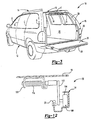
- Figure 1 is a rear perspective view of the present invention vehicle with the rear window partially open;
- Figure 2 is a rear perspective view of the present invention vehicle with the window partially open and the rear gate assembly pivoted upward to an open position;
- Figure 3 is a rear perspective view of the present invention vehicle with the tailgate of the rear gate assembly pivoted downward;
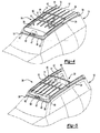
- Figure 4 is a front perspective view of the present invention retractable roof in a closed position;
- Figure 5 is a front perspective view of the present invention retractable roof in an open position;
- Figure 6 is a front perspective view of the present invention roof assembly;
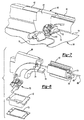
- Figure 7 is an enlarged perspective view of a guide member and guide rail with front roller mechanism;
- Figure 8 is an exploded view of the guide rail and guide member shown in Figure 7;
- Figure 9 is a perspective view of the guide member roller mechanism;
- Figure 10 is a perspective view of the guide member bracket assembly;
- Figure 11a is a cross-sectional view of roof panel in the closed position;
- Figure 11b is a cross-sectional view of the roof panel in a partially open position;
- Figure 11c is a cross-sectional view of the roof panel moving toward the open position; and
- Figure 12 is a cross-sectional view of a rear guide member.
-
- A
vehicle 10 utilizing the present invention is shown in Figures 1-3. Thevehicle 10 shown has a four-door body 12 that includes A, B, C, D pillars. Thebody 12 has aroof 14 that includes the present inventionretractable roof panel 16. Theroof panel 16 has arear header 17, which may commonly be referred to as a D pillar header for the four-door vehicle shown. Awiper 19 may be mounted to therear header 17. - A
rear body portion 18 defines arear opening 20. Arear gate assembly 22 is mounted on therear body portion 18 to enclose therear opening 20. Thegate assembly 20 may include aframe 28 supporting a lower body ortail gate 26 and awindow 24. However, it is to be understood that any arrangement may be used for therear gate assembly 22. As shown in Figure 1, thewindow 24 may be lowered from anupper boundary 21 defined by therear header 17 into thelower body 26 to provide partial access to thecargo area 30 or for manipulating theroof panel 16 during opening and closing. As shown in Figure 2, the window andtailgate 26 may move pivotally upward with theframe 28 to act as a lift gate. For configurations in which thewiper 19 is mounted to therear header 17, thewindow 24 may be partially opened to ensure clearance of thewiper 19. As shown in Figure 3, theframe 28 may remain secured to therear body portion 18 to manipulate thetail gate 26. Thewindow 24 may be lower into thetail gate 26, and the tail gate may be rotated downward to permit access to thecargo area 30 of the interior cabin so that objects may be easily slid into the rear of the vehicle. It can be appreciated that the present invention vehicle, as shown in Figures 1-3, functions to permit cargo of a relatively limited height to be stored in thecargo area 30 of thevehicle 10. - Referring to Figures 4-6, the
roof 14 may be provided by aroof assembly 36 that may be secured to the rest of the vehicle body during assembly of thevehicle 10. Theroof assembly 36 may include all of the features discussed below in addition to other features and interior trim such as head liner and dome lights, etc. Theroof assembly 36 includes theroof 14 that defines a generally U-shaped roof opening 37, best seen in Figure 5. Theroof panel 16 is a rigid unitary structure that is preferably constructed from a fiber reinforced polymer material. Theroof 14 may also be a fiber reinforced polymer material or may be stamped steel. Theroof assembly 36 has aperimeter 39 of which therear header 17 defines therearward end 54 of theperimeter 39. Theroof 14 includesguide rails 40 that define a path of theroof panel 16. Theguide rails 40 are mounted to theexterior surface 38 of theroof 14. The guide rails includelongitudinal members 42 that are secured to theroof 14 bysupport members 44.Luggage racks 48 may be arranged laterally between the guide rails 40. - A
wind deflector 46 may be arranged at aforward end 47 of theroof 14 to direct wind over theroof panel 16 when theroof panel 16 is in the open position, as shown in Figure 5. Amotor 50 may be mounted on theexterior surface 38 of theroof 14 beneath thewind deflector 46. Drivecables 52 may be coupled to a portion of theroof panel 16 and connected to themotor 50 driving theroof panel 16 between the closed position (shown in Figure 4) and the open position (shown in Figure 5). Thecables 52 may have a helical outer member typical of the type used in sunroofs. - The
roof panel 16 of the present invention is stowed on the outside of thevehicle 10 adjacent to theexterior surface 38. Thelower portion 49 of theroof panel 16 may be arranged partially under thewind deflector 46 with theroof panel 16 beneath the luggage racks 48. Unlike typical sunroof assemblies, the presentinvention roof panel 16 moves from therearward end 54 of the vehicle to theforward end 47 of the vehicle. Additionally, theroof panel 16 includes therear header 17 such that when theroof panel 16 is moved to the open position and therear gate assembly 22 is moved to the open position very large items that may extend beyond the plane of theroof 14 may be placed easily into thecargo area 30. - Referring to Figure 6, the
roof panel 16 is shown supporting theforward portion 49 in the guide rails 40 byguide members 60.Rear guide member 62 support the rear of theroof panel 16 on theroof 14, which will be discussed in more detail below. The forward portion of theroof opening 37 includes a first wall portion 64. Theforward portion 49 of theroof panel 16 includes a second wall portion 65 that is adjacent to the first wall portion 64 when theroof panel 16 is in the closed position. Alatch assembly 66 is mounted underneath the wall portions 64 and 65. The latch may be arranged in any suitable location. Thelatch assembly 66 locks theroof panel 16 to theroof 14 where the roof is in the closed position. Preferably, two spaced apart latchassembly 66 are used to reduce the stress on theroof panel 16. - Referring to Figures 7-9, the
forward guide members 60 are received within thecenter support members 44. Theguide members 60 travel along a path in thelongitudinal members 42 andsupport members 44 defined by achannel 74. For the embodiment shown, the rearlongitudinal members 42 are for aesthetics and do not support theroof panel 16. As shown in Figure 8, thesupport member 44 includes apocket 70 received in a recess in the roof 14 (not shown) and sealed thereto by agasket 72. As theroof panel 16 moves from the closed position to the open position theguide members 60 travel up along thechannel 74 defined in thesupport member 44 to raise theforward portion 49 of theroof panel 16. The longitudinal 42 andsupport 44 members are secured to one another using atongue 76 andgroove 78 arrangement and fasteners (now shown). Thedrive cables 68 andwires 69 may be routed through thechannel 74 and carried by a portion of theguide member 60. The wires may be routed to a rear brake light and/or thewiper 19. - Referring to Figure 9, a
guide member 60 includes acage 80 that carries a pair offirst rollers 82 rotatable about horizontal axles andsecond rollers 84 rotatable about vertical axes. Thefirst rollers 82 carry the load of theroof panel 16 on the bottom of thechannel 74. Thesecond rollers 84 may ride a long a side of thechannel 74 to minimize friction during any vibration of theroof panel 16 as it moves between the open and closed positions. However, it is to be understood that any number and configuration of rollers may be used. Thecage 80 includes alateral member 86 that extends from the cage 82 ablock 88 that is secured to theroof panel 16. Thelateral member 86 may include a damper to further minimize roof panel vibrations. - A
bracket 90 having a generally verticalelongated aperture 92 is arranged between thecage 80 and theroof panel 16 with thelateral member 86 disposed within theaperture 92. Theaperture 92 permits therollers cage 80 to move upward if thefirst rollers 82 must travel over debris trapped on the bottom of thechannel 74. A biasingmember 94 or spring normally urges thelateral member 86 downward in theaperture 92. Opposing ends 95 of thespring 94 are retained with retainingpockets 97. Thedrive cable 68 andwires 69 may be respectively mounted oncable 96 andwire 98 mounts secured to thebracket 90. Themotor 50 pulls theroof panel 16 forward to the open position. Theroof panel 16 is closed by pushing it and lowering it under the force of its own weight. - A
rear guide member 62 is best shown in Figures 11a-11c and 12. Unlike theforward guide member 60, therear guide members 62 do not ride within the guide rails 40. However, it is to be understood that therear guide member 62 may be configured such that they do ride within the guide rails 40 similar to theguide members 60. Therear guide member 62 rides along a rear aperture, which may defined by theroof assembly 36 or another portion of thevehicle 10, and adrain trough 106 which is defined by a channel arranged about the perimeter roof opening 37, which is best shown in Figure 12. Therear guide member 62 includes abracket 108 secured to theroof panel 16. Thebracket 108 pivotally supports anarm 110 havingrollers 112. Aspring 114 biases thearm 110 forward away from therear header 17. Referring to Figure 11a, theroof panel 16 is show in a closed and locked position in which thearm 110 is tilted rearward with aroller 112 received in arecess 118 in therear aperture 104. In this position, the rear of theroof panel 16 cannot be lifted until the roof panel is moved forward. As theroof panel 16 is moved forward, as shown in Figure 11b, thearm 110 rotates forward as theroof panel 16. Thespring 114 urges thearm 110 to unseat one of therollers 112 from therecess 118. As theroof panel 16 continues to move forward, as shown in Figure 11c, therollers 112 move along thedrain trough 106. Therear guide member 62 configuration provides enough lift to the rear of theroof panel 16 such that theroof panel 16 may clear theexterior surface 38 of theroof 14 when in the fully opened position. - In operation, the
rear gate assembly 22 may be manipulated as described in relation to Figures 1-3 above to permit access to thecargo area 30. However, when increased access to thecargo area 30 is desired, for example for cargo items having a height that exceeds the plane of theroof 14, theroof panel 16 may be retracted. To retract theroof panel 16, thelatch assembly 66 must be actuated to unlock theforward portion 49 of theroof panel 16 from theroof 14. Theforward guide member 60 will begin to move up thechannel 74 in thesupport member 44, and therear guide member 62 will rotate forward such that one of therollers 112 moves out of engagement with therecess 118. Theforward guide member 60 will move along thechannels 74 within thelongitudinal member 42, and therear guide member 62 and will move along thedrain trough 106. Theforward portion 49 of theroof panel 16 will preferably be disposed beneathwind deflector 46. Preferably when opening theretractable roof panel 16, thewindow 24 will be lowered into thelower body 26 to minimize the force on thewindow 24 when traveling along a road with theretractable roof panel 16 in the open position. - The invention has been described in an illustrative manner, and it is to be understood that the terminology that has been used is intended to be in the nature of words of description rather than of limitation. The
vehicle 10 includes electronic hardware, software, and actuators typically available. The sequence used to open and close theroof panel 16 may be programmed and initiated by operation of a switch. Obviously, many modifications and variations of the present invention are possible in light of the above teachings. It is, therefore, to be understood that within the scope of the appended claims the invention may be practiced otherwise than as specifically described.
Claims (33)
- A vehicle comprising:a vehicle body having a roof with a roof opening extending to a rear of said roof, and said vehicle body having a rear body portion with a rear opening extending to said roof opening to form a large opening with said roof opening;a rear gate assembly disposed within said rear opening in a closed gate position; anda retractable roof panel movable from an open roof position to a closed roof position in which said roof panel is disposed within said opening, said roof panel including a rear header that defines an upper boundary of said rear opening with said roof panel in said closed roof position, and a portion of said rear gate assembly adjacent to said rear header with said roof panel and said rear gate assembly in said closed roof and gate positions.
- The vehicle according to claim 1, wherein said rear gate assembly includes a lower body and a window arranged above said lower body, wherein said window is said portion adjacent to said rear header with said roof panel and said rear gate assembly in said closed roof and gate positions.
- The vehicle according to claim 2, wherein said lower body is a tailgate movable between a closed tailgate position in which said tailgate is at least partially disposed within said rear opening and an open gate position in which said window is received within said lower body with said tailgate pivotally removed from said rear opening.
- The vehicle according to claim 2 or 3, wherein said rear gate assembly includes a frame pivotally supported within said rear opening in said closed gate position, said lower body and said window pivotally supported on said frame, and said frame rotatable upward and outward relative to said rear body portion to said open gate position.
- The vehicle according to any preceding claim, wherein said vehicle body defines an interior cabin and said roof has an exterior surface opposite said interior cabin with said roof panel adjacent said exterior surface in said closed roof position.
- The vehicle according to claim 5, further including spaced apart guide rails supported on said exterior surface with at least a portion of said roof panel supported by said guide rails.
- The vehicle according to claim 5 or 6, wherein said cabin includes a forward portion and said roof panel moves over said forward portion in said closed roof position.
- A method of accessing a cargo area of a vehicle comprising the steps of:a) providing a roof panel that defines a rear header;b) providing a rear gate assembly having a portion adjacent to the header;c) moving at least the portion of the rear gate assembly to expose a rear opening;d) retracting the roof panel to expose a roof opening; ande) creating one large opening including the rear opening and the roof opening.
- The method according to claim 8, wherein the rear gate assembly includes a lower body and a window arranged above the lower body.
- The method according to claim 8 or 9, wherein step c) includes retracting the window into the lower body and rotating the lower body downward away from the roof opening.
- The method according to any one of claims 8 to 10, wherein step c) includes retracting the window into the lower body.
- The method according to any one of claims 8 to 11, wherein step d) includes raising the roof panel and stowing the roof panel adjacent to an exterior surface of the roof.
- The method according to claim 12, wherein step d) includes moving the roof panel forward away from the rear opening.
- A roof assembly for a vehicle comprising:a roof having a roof opening extending to a rear of said roof, said roof having an exterior surface and forward and rearward ends;spaced apart guide rails supported on said exterior surface defining a path;a guide member received in each of said guide rails movable along said path; and
a retractable roof panel with a portion supported by said guide members and movable along said path from an open roof position to a closed roof position in which said roof panel is disposed within said roof opening, said roof panel defining a rear header at said rearward end with said rear header moving toward said forward end when moving between said closed and open roof positions, respectively. - The roof assembly according to claim 14, wherein said roof includes a perimeter with said rear head defining a portion of said perimeter in said closed roof position.
- The roof assembly according to claim 14 or 15, wherein said roof opening is generally U-shaped.
- The roof assembly according to any preceding claim, wherein a motor is on said exterior surface, said motor interconnected with said roof panel driving said roof panel between said closed and open roof positions.
- The roof assembly according to any preceding claim, further including a wiper mounted on said rear header.
- The roof assembly according to any preceding claim, wherein said roof panel is a unitary rigid structure.
- The roof assembly according to any one of claims 14 to 19, wherein roof includes a first wall portion defining a forward portion of said roof opening, and said roof panel includes a second wall portion adjacent to said first wall portion in said closed roof position with at least one latch assembly mounted between said wall portion locking said roof panel to said roof in said closed roof position.
- The roof assembly according to any one of claims 14 to 20, wherein said guide member includes a roller assembly received within a channel in each of said guide rails.
- The roof assembly according to claim 21, wherein said roller assembly includes a first roller having a horizontal rotational axis and a second roller having a vertical rotational axis.
- The roof assembly according to claim 22, wherein said roller assembly includes a pair of each of said first and second rollers.
- The roof assembly according to claim 22 or 23, wherein said guide member includes a cage supporting said rollers with a lateral member interconnecting said cage to said roof panel.
- The roof assembly according to claim 24, wherein said lateral member includes a damper.
- The roof assembly according to claim 24 or 25, wherein said guide member includes a bracket having an elongated generally vertical aperture with said lateral member disposed therein.
- The roof assembly according to claim 26, wherein said guide member includes a biasing member urging said lateral member downward in said aperture.
- The roof assembly according to claim 26 or 27, further including a drive cable attached to said bracket for moving said roof panel between closed and open roof positions.
- The roof assembly according to any one of claim 14 to 28, further including a luggage rack arranged between said guide rails with said roof panel interposed between said luggage rack and said exterior surface in said open roof position.
- A method of exposing an opening in a vehicle roof comprising the steps of:a) providing a roof assembly having a roof including roof opening with a roof panel disposed therein defining a closed roof position, the roof panel including a rear header and a perimeter partially defined by the rear header; andb) retracting the roof panel from the closed roof position to expose the roof opening defining an open roof position.
- The method according to claim 30, wherein step b) includes raising the roof panel and stowing the roof panel adjacent to an exterior surface of the roof.
- The method according to claim 30 or 31, wherein step a) includes a wind deflector at a forward end of the roof, and step b) includes moving the roof panel toward the wind deflector.
- The method according to claim 30 or 31 or 32, further including step c) includes unlocking a latch that secures the roof panel to the roof, wherein step c) occurs prior to step b).
Applications Claiming Priority (4)
| Application Number | Priority Date | Filing Date | Title |
|---|---|---|---|
| US25223800P | 2000-11-20 | 2000-11-20 | |
| US252238P | 2000-11-20 | ||
| US09/876,519 US6866335B2 (en) | 2001-06-07 | 2001-06-07 | Exteriorly located motor for sunroof |
| US876519 | 2001-06-07 |
Publications (3)
| Publication Number | Publication Date |
|---|---|
| EP1207067A2 true EP1207067A2 (en) | 2002-05-22 |
| EP1207067A3 EP1207067A3 (en) | 2003-04-23 |
| EP1207067B1 EP1207067B1 (en) | 2007-06-13 |
Family
ID=26942149
Family Applications (1)
| Application Number | Title | Priority Date | Filing Date |
|---|---|---|---|
| EP01309757A Expired - Lifetime EP1207067B1 (en) | 2000-11-20 | 2001-11-20 | Vehicle |
Country Status (3)
| Country | Link |
|---|---|
| US (1) | US6494528B2 (en) |
| EP (1) | EP1207067B1 (en) |
| DE (1) | DE60128878T2 (en) |
Cited By (4)
| Publication number | Priority date | Publication date | Assignee | Title |
|---|---|---|---|---|
| EP1614567A3 (en) * | 2004-07-07 | 2007-09-26 | GM Global Technology Operations, Inc. | Multi-part tailgate for a vehicle |
| FR2920736A1 (en) * | 2007-09-10 | 2009-03-13 | Peugeot Citroen Automobiles Sa | Body shell for e.g. four-door sedan, has roof including upper cross-piece whose ends are integrated to lateral sides, and roof panel placed in upper part of vehicle, where cross-piece forms roof panel supporting unit |
| US20230226986A1 (en) * | 2018-08-20 | 2023-07-20 | Freedom Surveillance, LLC | Surveillance equipment platform having a retractable telescoping structure that fully retracts within a vehicle and which has surveillance equipment mounted thereon, and sealing device mounted to the telescoping structure |
| US20240253429A1 (en) * | 2023-01-30 | 2024-08-01 | Nissan North America, Inc. | Vehicle door assembly |
Families Citing this family (24)
| Publication number | Priority date | Publication date | Assignee | Title |
|---|---|---|---|---|
| EP1314599B1 (en) * | 2001-11-22 | 2007-06-27 | Inalfa Roof Systems Group B.V. | Vehicle |
| US6641201B1 (en) * | 2002-09-17 | 2003-11-04 | General Motors Corporation | Convertible bed cover for a vehicle |
| CN1309614C (en) * | 2003-09-02 | 2007-04-11 | 本田技研工业株式会社 | Rear part structure of vehicle |
| US6851741B1 (en) * | 2003-09-29 | 2005-02-08 | Donald E. Burg | Vehicle with extendable cargo and/or passenger area |
| EP1680295B1 (en) * | 2003-10-23 | 2008-09-17 | Magna International Inc. | Liftgate frame |
| US20050253406A1 (en) * | 2004-05-12 | 2005-11-17 | Faubert Robert J | Vehicle closure with multiple opening modes |
| US7114769B2 (en) * | 2004-06-17 | 2006-10-03 | Asc Incorporated | Automotive vehicle open air system |
| US7163260B2 (en) * | 2004-06-17 | 2007-01-16 | Asc Incorporated | Automotive vehicle open air system |
| US20050280290A1 (en) * | 2004-06-17 | 2005-12-22 | Urban Michael J | Automotive vehicle open air system |
| US20050280293A1 (en) * | 2004-06-17 | 2005-12-22 | Macnee Arthur L Iii | Automotive vehicle open air system |
| DE202005007475U1 (en) * | 2005-05-11 | 2005-07-14 | Arvinmeritor Gmbh | Guide rail for a motor vehicle sliding roof system |
| US7222908B1 (en) * | 2006-01-27 | 2007-05-29 | Asc Incorporated | Automotive open air system |
| US7938483B2 (en) | 2007-05-24 | 2011-05-10 | Specialty Vehicle Acquisition Corp. | Movable vehicular roof |
| US7527328B2 (en) * | 2007-05-24 | 2009-05-05 | Specialty Vehicle Acquisition Corp. | Modular roof system for automotive vehicle |
| US8167357B2 (en) | 2010-08-06 | 2012-05-01 | Honda Motor Co., Ltd. | Dual action rear hatch |
| US8132846B2 (en) | 2010-08-06 | 2012-03-13 | Honda Motor Co., Ltd. | Slide hatch assembly |
| US8152230B2 (en) | 2010-08-06 | 2012-04-10 | Honda Motor Co., Ltd. | Closure assembly for vehicle |
| US8376449B2 (en) | 2010-08-06 | 2013-02-19 | Honda Motor Co., Ltd. | Spoiler for rear hatch closure assembly |
| US8333426B2 (en) | 2010-08-06 | 2012-12-18 | Honda Motor Co., Inc. | Rise up panoramic roof for a vehicle |
| JP2016084078A (en) * | 2014-10-28 | 2016-05-19 | 株式会社豊田自動織機 | Vehicle door structure |
| US10358854B1 (en) | 2017-04-05 | 2019-07-23 | Wudthipong Guygaew | Tailgate system for a vehicle with astride opening features |
| US10457126B2 (en) | 2017-05-12 | 2019-10-29 | Michael P. Held | Open-air car canopy and cover assembly and method of operation |
| US12005764B2 (en) * | 2022-01-27 | 2024-06-11 | Nissan North America, Inc. | Rear door assembly |
| CN118893956A (en) * | 2024-08-16 | 2024-11-05 | 长城汽车股份有限公司 | A vehicle |
Family Cites Families (41)
| Publication number | Priority date | Publication date | Assignee | Title |
|---|---|---|---|---|
| US2203931A (en) | 1938-04-11 | 1940-06-11 | Ternstedt Mfg Co | Sliding top |
| FR1431241A (en) * | 1964-03-16 | 1966-03-11 | Golde Gmbh H T | Motor vehicle with a rigid opening roof, the body of which has a door in the rear wall |
| US3612601A (en) * | 1970-01-26 | 1971-10-12 | Gen Motors Corp | Vehicle closure arrangement |
| US4043590A (en) | 1975-01-13 | 1977-08-23 | Skytrends, Inc. | Sliding roof assembly |
| US4063774A (en) * | 1976-08-24 | 1977-12-20 | Hanks George L | Convertible station wagon roof |
| JPS5387426A (en) * | 1977-01-12 | 1978-08-01 | Nissan Motor Co Ltd | Apparatus for sliding slide door for vehicle |
| US4272121A (en) * | 1978-06-19 | 1981-06-09 | Kim Sunyong P | Station wagon with adjustable rear roof panel |
| DE2923888C2 (en) | 1979-06-13 | 1983-01-05 | Webasto-Werk W. Baier GmbH & Co, 8035 Gauting | Sunroof for automobiles |
| DE3408056A1 (en) | 1984-03-05 | 1985-09-05 | Webasto-Werk W. Baier GmbH & Co, 8035 Gauting | LIFTING AND SUNROOF FOR VEHICLES |
| DE3420349A1 (en) * | 1984-05-30 | 1985-12-05 | Bayerische Motoren Werke Ag | MULTIPURPOSE PASSENGER VEHICLES, PARTICULARLY COMBINED |
| JPH0324411Y2 (en) | 1984-12-14 | 1991-05-28 | ||
| DE3545869A1 (en) | 1985-03-27 | 1986-10-09 | Webasto-Werk W. Baier GmbH & Co, 8035 Gauting | VEHICLE ROOF |
| CA1267642A (en) | 1986-12-18 | 1990-04-10 | Marcel Audet | Vehicle roof rack |
| ES2008789A6 (en) | 1987-03-11 | 1989-08-01 | Rockwell Golde Gmbh | Sliding roof for automobiles |
| JPH05450Y2 (en) | 1987-07-31 | 1993-01-07 | ||
| GB2229973B (en) | 1989-02-27 | 1993-01-20 | Nissan Motor | Sunroof structure for automotive vehicle |
| US5197779A (en) | 1989-06-27 | 1993-03-30 | Mazda Motor Corporation | Power sliding sunroof |
| US5114208A (en) | 1989-08-04 | 1992-05-19 | Aisin Seiki Kabushiki Kaisha | Sliding mechanism for sunroof |
| DE4002278C1 (en) | 1990-01-26 | 1991-07-11 | Webasto Ag Fahrzeugtechnik, 8035 Stockdorf, De | |
| US5069501A (en) | 1990-08-03 | 1991-12-03 | General Motors Corporation | Spoiler sunroof control mechanism |
| NL9200165A (en) | 1992-01-30 | 1993-08-16 | Vermeulen Hollandia Octrooien | SPOILER ROOF. |
| US5558388A (en) | 1992-02-05 | 1996-09-24 | Webasto Karosseriesysteme Gmbh | Vehicle roof |
| DE4227402C1 (en) | 1992-08-19 | 1994-01-13 | Webasto Karosseriesysteme | Vehicle roof |
| FR2695878B1 (en) | 1992-09-24 | 1994-12-16 | Heuliez Webasto | Opening and sliding sunroof. |
| DE4330426A1 (en) | 1993-09-08 | 1995-03-09 | Hs Tech & Design | Device for guiding a vehicle sunroof cover |
| US5417358A (en) | 1993-10-12 | 1995-05-23 | Haselgrove; Michael B. | Pull down utility roof rack |
| US5464267A (en) | 1994-04-18 | 1995-11-07 | Webasto Sunroofs, Inc. | Stable lift mechanism for spoiler sun roof panel |
| WO1996001192A1 (en) | 1994-07-05 | 1996-01-18 | Asc Incorporated | Automobile sunroof assembly and control system |
| US5746475A (en) | 1995-06-07 | 1998-05-05 | Asc Incorprated | Drive mechanism for an automotive vehicle sunroof assembly |
| US6056352A (en) | 1994-07-05 | 2000-05-02 | Asc Incorporated | Sunroof assembly for an automotive vehicle and control system for operating a sunroof assembly |
| DE19512342C2 (en) | 1995-04-01 | 1998-05-14 | Webasto Karosseriesysteme | Vehicle roof |
| US5884824A (en) | 1996-07-23 | 1999-03-23 | Spring, Jr.; Joseph N. | Equipment transport rack for vehicles providing improved loading accessibility |
| US5673831A (en) | 1996-08-14 | 1997-10-07 | Spratt; William L. | Tip down vehicle top carrier |
| DE19650227C1 (en) | 1996-12-04 | 1997-11-27 | Webasto Karosseriesysteme | Motor vehicle roof with cable connection between adjustable roof element and fixed roof surface |
| DE19703818C1 (en) | 1997-02-01 | 1998-04-02 | Webasto Systemkomponenten Gmbh | Sliding roof for motor vehicle |
| JPH10278591A (en) | 1997-04-09 | 1998-10-20 | Aisin Seiki Co Ltd | Sunroof equipment |
| NL1006437C2 (en) | 1997-07-01 | 1999-01-05 | Inalfa Ind Bv | Open roof construction for a vehicle. |
| DE19741134C1 (en) | 1997-09-12 | 1998-10-15 | Rockwell International Gmbh | Sun roof of motor vehicle |
| NL1009743C2 (en) * | 1998-07-27 | 2000-01-28 | Inalfa Ind Bv | Open roof construction for a vehicle, as well as a vehicle equipped with such an open roof construction. |
| US6068168A (en) | 1998-08-20 | 2000-05-30 | Kreisler; Stewart Orson | Vehicle top carrier apparatus |
| US6305740B1 (en) * | 1999-09-23 | 2001-10-23 | Delphi Technologies, Inc. | Automotive vehicle having moveable roof panel |
-
2001
- 2001-11-20 EP EP01309757A patent/EP1207067B1/en not_active Expired - Lifetime
- 2001-11-20 US US09/989,361 patent/US6494528B2/en not_active Expired - Fee Related
- 2001-11-20 DE DE60128878T patent/DE60128878T2/en not_active Expired - Fee Related
Non-Patent Citations (1)
| Title |
|---|
| None |
Cited By (5)
| Publication number | Priority date | Publication date | Assignee | Title |
|---|---|---|---|---|
| EP1614567A3 (en) * | 2004-07-07 | 2007-09-26 | GM Global Technology Operations, Inc. | Multi-part tailgate for a vehicle |
| FR2920736A1 (en) * | 2007-09-10 | 2009-03-13 | Peugeot Citroen Automobiles Sa | Body shell for e.g. four-door sedan, has roof including upper cross-piece whose ends are integrated to lateral sides, and roof panel placed in upper part of vehicle, where cross-piece forms roof panel supporting unit |
| US20230226986A1 (en) * | 2018-08-20 | 2023-07-20 | Freedom Surveillance, LLC | Surveillance equipment platform having a retractable telescoping structure that fully retracts within a vehicle and which has surveillance equipment mounted thereon, and sealing device mounted to the telescoping structure |
| US12157422B2 (en) * | 2018-08-20 | 2024-12-03 | Freedom Surveillance, LLC | Surveillance platform having a retractable telescoping structure that fully retracts within a vehicle and which has surveillance equipment mounted thereon, and sealing device mounted to the telescoping structure |
| US20240253429A1 (en) * | 2023-01-30 | 2024-08-01 | Nissan North America, Inc. | Vehicle door assembly |
Also Published As
| Publication number | Publication date |
|---|---|
| EP1207067B1 (en) | 2007-06-13 |
| EP1207067A3 (en) | 2003-04-23 |
| US20020060479A1 (en) | 2002-05-23 |
| DE60128878T2 (en) | 2008-02-28 |
| US6494528B2 (en) | 2002-12-17 |
| DE60128878D1 (en) | 2007-07-26 |
Similar Documents
| Publication | Publication Date | Title |
|---|---|---|
| EP1207067B1 (en) | Vehicle | |
| US6899382B2 (en) | Retractable roof panel | |
| US6672658B2 (en) | Vehicle with a vehicle roof that can be opened | |
| JP5119325B2 (en) | Modular sliding rigid panel roof system | |
| US6921492B2 (en) | Motor vehicle with a cargo space and cargo space door | |
| US5542735A (en) | Lengthwise movable vehicle roof | |
| US6874838B2 (en) | Motor vehicle with a tailgate | |
| US20040130183A1 (en) | Transformable vehicle | |
| US20050073167A1 (en) | Motor vehicle with improved rear functionality | |
| CN101557954B (en) | Movable roof element for a motor vehicle | |
| DE10028777B4 (en) | Vehicle with a convertible rear body | |
| US7410198B1 (en) | Automotive vehicle with repositionable D-pillar roof structure | |
| CN101218116B (en) | convertible car | |
| US5803534A (en) | Passenger car with a transparent top assembly | |
| EP2998141B1 (en) | Vehicle | |
| US7744145B2 (en) | Panoramic retractable top | |
| US20060022493A1 (en) | Motor vehicle with a convertible rear compartment | |
| US20060119141A1 (en) | Retractable roof for a vehicle, with movable arms and opening roof elements | |
| US20090146461A1 (en) | Motor vehicle equipped with a roof that can be opened | |
| US7222908B1 (en) | Automotive open air system | |
| US20250214402A1 (en) | Side door for a vehicle | |
| US20070170748A1 (en) | Vehicle having a hardtop roof | |
| US7992930B2 (en) | Vehicle having a reconfigurable cargo area |
Legal Events
| Date | Code | Title | Description |
|---|---|---|---|
| PUAI | Public reference made under article 153(3) epc to a published international application that has entered the european phase |
Free format text: ORIGINAL CODE: 0009012 |
|
| AX | Request for extension of the european patent |
Free format text: AL;LT;LV;MK;RO;SI |
|
| PUAL | Search report despatched |
Free format text: ORIGINAL CODE: 0009013 |
|
| AK | Designated contracting states |
Designated state(s): AT BE CH CY DE DK ES FI FR GB GR IE IT LI LU MC NL PT SE TR |
|
| AX | Request for extension of the european patent |
Extension state: AL LT LV MK RO SI |
|
| 17P | Request for examination filed |
Effective date: 20030602 |
|
| AKX | Designation fees paid |
Designated state(s): DE ES FR GB IT |
|
| RAP1 | Party data changed (applicant data changed or rights of an application transferred) |
Owner name: ARVINMERITOR TECHNOLOGY, LLC |
|
| GRAP | Despatch of communication of intention to grant a patent |
Free format text: ORIGINAL CODE: EPIDOSNIGR1 |
|
| RIN1 | Information on inventor provided before grant (corrected) |
Inventor name: ENGELGAU, STEVEN Inventor name: TOLINSKI, ROCH |
|
| GRAS | Grant fee paid |
Free format text: ORIGINAL CODE: EPIDOSNIGR3 |
|
| GRAA | (expected) grant |
Free format text: ORIGINAL CODE: 0009210 |
|
| AK | Designated contracting states |
Kind code of ref document: B1 Designated state(s): DE ES FR GB IT |
|
| REG | Reference to a national code |
Ref country code: GB Ref legal event code: FG4D |
|
| REF | Corresponds to: |
Ref document number: 60128878 Country of ref document: DE Date of ref document: 20070726 Kind code of ref document: P |
|
| ET | Fr: translation filed | ||
| PG25 | Lapsed in a contracting state [announced via postgrant information from national office to epo] |
Ref country code: ES Free format text: LAPSE BECAUSE OF FAILURE TO SUBMIT A TRANSLATION OF THE DESCRIPTION OR TO PAY THE FEE WITHIN THE PRESCRIBED TIME-LIMIT Effective date: 20070924 |
|
| PGFP | Annual fee paid to national office [announced via postgrant information from national office to epo] |
Ref country code: DE Payment date: 20071115 Year of fee payment: 7 |
|
| PLBE | No opposition filed within time limit |
Free format text: ORIGINAL CODE: 0009261 |
|
| STAA | Information on the status of an ep patent application or granted ep patent |
Free format text: STATUS: NO OPPOSITION FILED WITHIN TIME LIMIT |
|
| PG25 | Lapsed in a contracting state [announced via postgrant information from national office to epo] |
Ref country code: IT Free format text: LAPSE BECAUSE OF FAILURE TO SUBMIT A TRANSLATION OF THE DESCRIPTION OR TO PAY THE FEE WITHIN THE PRESCRIBED TIME-LIMIT Effective date: 20070613 |
|
| PGFP | Annual fee paid to national office [announced via postgrant information from national office to epo] |
Ref country code: FR Payment date: 20071108 Year of fee payment: 7 |
|
| 26N | No opposition filed |
Effective date: 20080314 |
|
| GBPC | Gb: european patent ceased through non-payment of renewal fee |
Effective date: 20071120 |
|
| PG25 | Lapsed in a contracting state [announced via postgrant information from national office to epo] |
Ref country code: GB Free format text: LAPSE BECAUSE OF NON-PAYMENT OF DUE FEES Effective date: 20071120 |
|
| REG | Reference to a national code |
Ref country code: FR Ref legal event code: ST Effective date: 20090731 |
|
| PG25 | Lapsed in a contracting state [announced via postgrant information from national office to epo] |
Ref country code: DE Free format text: LAPSE BECAUSE OF NON-PAYMENT OF DUE FEES Effective date: 20090603 |
|
| PG25 | Lapsed in a contracting state [announced via postgrant information from national office to epo] |
Ref country code: FR Free format text: LAPSE BECAUSE OF NON-PAYMENT OF DUE FEES Effective date: 20081130 |