EP1206809B1 - METHOD FOR MAINTAINING THE ELECTROLYTE LEVEL OF A NiCd STORAGE BATTERY - Google Patents
METHOD FOR MAINTAINING THE ELECTROLYTE LEVEL OF A NiCd STORAGE BATTERY Download PDFInfo
- Publication number
- EP1206809B1 EP1206809B1 EP00955768A EP00955768A EP1206809B1 EP 1206809 B1 EP1206809 B1 EP 1206809B1 EP 00955768 A EP00955768 A EP 00955768A EP 00955768 A EP00955768 A EP 00955768A EP 1206809 B1 EP1206809 B1 EP 1206809B1
- Authority
- EP
- European Patent Office
- Prior art keywords
- cell
- battery
- internal resistance
- measuring
- nicd
- Prior art date
- Legal status (The legal status is an assumption and is not a legal conclusion. Google has not performed a legal analysis and makes no representation as to the accuracy of the status listed.)
- Expired - Lifetime
Links
Images

Classifications
-
- H—ELECTRICITY
- H01—ELECTRIC ELEMENTS
- H01M—PROCESSES OR MEANS, e.g. BATTERIES, FOR THE DIRECT CONVERSION OF CHEMICAL ENERGY INTO ELECTRICAL ENERGY
- H01M10/00—Secondary cells; Manufacture thereof
- H01M10/42—Methods or arrangements for servicing or maintenance of secondary cells or secondary half-cells
- H01M10/48—Accumulators combined with arrangements for measuring, testing or indicating the condition of cells, e.g. the level or density of the electrolyte
- H01M10/484—Accumulators combined with arrangements for measuring, testing or indicating the condition of cells, e.g. the level or density of the electrolyte for measuring electrolyte level, electrolyte density or electrolyte conductivity
-
- H—ELECTRICITY
- H01—ELECTRIC ELEMENTS
- H01M—PROCESSES OR MEANS, e.g. BATTERIES, FOR THE DIRECT CONVERSION OF CHEMICAL ENERGY INTO ELECTRICAL ENERGY
- H01M50/00—Constructional details or processes of manufacture of the non-active parts of electrochemical cells other than fuel cells, e.g. hybrid cells
- H01M50/60—Arrangements or processes for filling or topping-up with liquids; Arrangements or processes for draining liquids from casings
-
- Y—GENERAL TAGGING OF NEW TECHNOLOGICAL DEVELOPMENTS; GENERAL TAGGING OF CROSS-SECTIONAL TECHNOLOGIES SPANNING OVER SEVERAL SECTIONS OF THE IPC; TECHNICAL SUBJECTS COVERED BY FORMER USPC CROSS-REFERENCE ART COLLECTIONS [XRACs] AND DIGESTS
- Y02—TECHNOLOGIES OR APPLICATIONS FOR MITIGATION OR ADAPTATION AGAINST CLIMATE CHANGE
- Y02E—REDUCTION OF GREENHOUSE GAS [GHG] EMISSIONS, RELATED TO ENERGY GENERATION, TRANSMISSION OR DISTRIBUTION
- Y02E60/00—Enabling technologies; Technologies with a potential or indirect contribution to GHG emissions mitigation
- Y02E60/10—Energy storage using batteries
Definitions
- NiCd nickel cadmium
- US-A-4937528 discloses a method for monitoring the status of an automotive battery to determine battery capacity, state of charge and certain fault conditions.
- a method for maintaining the electrolyte level of a NiCd storage battery of a given rated capacity after determining the amount of water to be added to individual cells of the NiCd storage battery comprising the step of:
- the electrolyte level can be determined by observing the electrical or electrochemical behavior of the cell during a charge pulse.
- One method measures the internal resistance of the cells of the battery.
- Another method measures the polarization value of the cells.
- the measured quantity is correlated with an amount of water added to reduce the measured parameter to an acceptable value and restore the electrolyte level and the electrolyte level and the performance of the cell.
- One aspect of this technique is the process of determining the correlation between the measured parameter and the quantities of water added. Another aspect is the use of this correlation to restore the electrolyte level.
- the battery Initially, the battery must be in a ready state.
- the battery containing one or more cells, is attached to a charging system (not shown).
- the battery is charged for a period t at a charge rate Cl until each of the cells has an open-circuit voltage of at least v, volts.
- v i 1.26 volts.
- the period t can be 15 minutes, although other values of t can be selected as suits the application.
- the charge rate C/ can be C/10, where C is the manufacturer's rated capacity of the battery, although the parameter can vary from greater than 1 to 100, or perhaps an even greater number, again depending on the application and the battery under test. For a battery having a capacity of 30Ah, the charge current would be 3 amps.
- a battery 10 is subjected to an internal resistance test cycle.
- a step charge current or pulse of C amps is applied to the entire battery 10 (the value C set by the battery rating).
- a discharge pulse may be employed.
- the current starts at zero and goes to C instantaneously or nearly instantaneously, and is maintained at that value for a period of time, e.g., 5 seconds, after which it returns instantaneously to zero.
- the step charge is applied, the battery response voltage is measured across each cell 12.
- the internal resistance of each cell 12 is determined by calculating the value of dV/dI during the falling portion of the step charge pulse (see Figure 2), although one might use other portions of the pulse to measure dV/dI.
- dV/dI Depending on the level of electrolyte in a given cell 12, the value of dV/dI will vary. By adding water and then measuring dV/dI, the amount of water needed to return the value of cell resistance to an acceptable number can be determined. This relationship can be collected in a table or expressed as an algorithm (or depicted in a graph), as desired. Since there may be a time lag between adding water and the final value of dV/dI, one may need to perform the measurements iteratively to arrive at stabilized values of internal resistance. Following the iterative process, one would arrive at tables such as those shown below for 30Ah and 10Ah batteries for a 5 second pulse width (Tables A and B, respectively).
- the values of acceptable maximum internal resistance, indicative of a proper electrolyte level were selected to be 2 m and 4 m, per cell, for the respective storage batteries, although greater or lesser values could have been selected.
- Other pulse widths (t) and amplitudes (C) may be employed but of course will result in different table values.
- the batteries utilized were manufactured by SAFT America, Inc., San Diego, CA, model no. M81757/7-2 (10 Ah) and model no. M81757/9-3 (30 Ah).
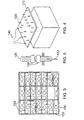
- FIG. 3 An arrangement for measuring the parameters of individual cells of a battery 100 is shown in Figures 3-5.
- the battery 100 has terminals 104 allowing direct electrical access to each of the cells 102.
- a battery terminal contact fixture 110 shown in Figure 4, has spring-loaded contacts 120 positioned to make contact with the terminals 104 of the battery cells 102.
- the contacts 120 can have spring-loaded points 122 and positioning and tightening nuts 124 for adjusting the position of each contact 120.
- the contact fixture 110 has a substrate or platform 112, manufactured from a suitable insulating material, which supports the spring-loaded contacts 120.
- Cabling 140 (shown attached to a few exemplary contacts 120) to provide the connections illustrated in Figure 1 would be connected to the apparatus for measuring resistance (or, more correctly, dV/dI).
- the cabling may take the form of individual wires, a ribbon cable, or any other suitable arrangement.
- the current pulse may be provided using a commercially-available power supply such as a Hewlett-Packard Model No. HP-6032A power supply and the parameters may be measured using commercially-available equipment such as a National Instrument Data Acquisition Card No. AT-MIO-16XE-50.
- a previously untested battery can be tested to determine whether the electrolyte levels in the cells are sufficient.
- the cells are again charged to at least voltage v i and then a pulse of the proper duration is applied to the battery.
- the quantity dV/dI is measured for each cell and the indicated quantity of water is added to the cells as dictated by the measurements of dV/dI.
- the same charge current and pulse width as used to create the tables must be utilized when the test is performed to provide the proper correlation between the measured values of internal resistance and the amount of water to be added.
- two iterations of the pulse test, accompanied by the indicated addition of water are sufficient to reduce the internal resistance of the battery cells to an acceptable level.
- the measurements discussed above utilized a direct current pulse.
- other devices could be used to measure the internal resistance of the cells.
- a milliohmeter such as the Hewlett-Packard HP4338A could be employed to generate an appropriate set of tables or curves.
- the polarization value is defined as the change in cell voltage, over the course of a pulse of current of constant value, divided by the amplitude of the pulse (in amps). From the polarization values, one can generate a table similar to those shown above, i.e., polarization values vs. the amount of water that must be added. When utilizing polarization value tables, care must be taken to apply pulses of the same width and magnitude as used to generate the tables.
Landscapes
- Chemical & Material Sciences (AREA)
- Chemical Kinetics & Catalysis (AREA)
- Electrochemistry (AREA)
- General Chemical & Material Sciences (AREA)
- Engineering & Computer Science (AREA)
- Manufacturing & Machinery (AREA)
- Secondary Cells (AREA)
- Investigating Or Analysing Materials By Optical Means (AREA)
- Hybrid Cells (AREA)
Abstract
Description
- If a cell of a nickel cadmium (NiCd) battery is overcharged, electrolysis of the water may occur, decreasing the electrolyte level in the cell. If a proper electrolyte level is not maintained, the cell will not function properly. Although the electrolyte level can be physically measured, a noninvasive, rapid technique would be highly desirable.
- US-A-4937528 discloses a method for monitoring the status of an automotive battery to determine battery capacity, state of charge and certain fault conditions.
- According to the present invention there is provided a method for maintaining the electrolyte level of a NiCd storage battery of a given rated capacity after determining the amount of water to be added to individual cells of the NiCd storage battery, said method comprising the step of:
- measuring the internal resistance or determining the polarization value
sequentially of each of the individual cells of the NiCd battery, and said method being
further characterized by the steps of:
- comparing the internal resistance or polarization values for each cell of the NiCd battery against a prior determined table correlating said values and amount of water to be added for a NiCd battery of said given capacity, the charge current or pulse width used to create said predetermined table having the same value as the charge current or pulse width used during the measuring of the intemal resistance or determining the polarization value of each of the individual cells of the NiCd battery, and
- adding to each cell individually the amount of water as determined from said predetermined table.
-
- The electrolyte level can be determined by observing the electrical or electrochemical behavior of the cell during a charge pulse. One method measures the internal resistance of the cells of the battery. Another method measures the polarization value of the cells. In either case, the measured quantity is correlated with an amount of water added to reduce the measured parameter to an acceptable value and restore the electrolyte level and the electrolyte level and the performance of the cell. One aspect of this technique is the process of determining the correlation between the measured parameter and the quantities of water added. Another aspect is the use of this correlation to restore the electrolyte level.
-
- Figure 1 is a schematic diagram of an apparatus for determining the amount of water to be added to the cells of a storage battery;
- Figure 2 is a waveform diagram of current and voltage for a cell under test; and
- Figures 3-5 are drawings of the top of a battery, a battery terminal contact fixture, and a spring-loaded contact for the battery terminal contact fixture, respectively.
-
- Initially, the battery must be in a ready state. The battery, containing one or more cells, is attached to a charging system (not shown). The battery is charged for a period t at a charge rate Cl until each of the cells has an open-circuit voltage of at least v, volts. In the case of a NiCd battery, vi= 1.26 volts. The period t can be 15 minutes, although other values of t can be selected as suits the application. The charge rate C/ can be C/10, where C is the manufacturer's rated capacity of the battery, although the parameter can vary from greater than 1 to 100, or perhaps an even greater number, again depending on the application and the battery under test. For a battery having a capacity of 30Ah, the charge current would be 3 amps.
- Utilizing the circuit of Figure 1, a
battery 10 is subjected to an internal resistance test cycle. A step charge current or pulse of C amps is applied to the entire battery 10 (the value C set by the battery rating). Alternatively, a discharge pulse may be employed. The current starts at zero and goes to C instantaneously or nearly instantaneously, and is maintained at that value for a period of time, e.g., 5 seconds, after which it returns instantaneously to zero. As the step charge is applied, the battery response voltage is measured across each cell 12. The internal resistance of each cell 12 is determined by calculating the value of dV/dI during the falling portion of the step charge pulse (see Figure 2), although one might use other portions of the pulse to measure dV/dI. - Depending on the level of electrolyte in a given cell 12, the value of dV/dI will vary. By adding water and then measuring dV/dI, the amount of water needed to return the value of cell resistance to an acceptable number can be determined. This relationship can be collected in a table or expressed as an algorithm (or depicted in a graph), as desired. Since there may be a time lag between adding water and the final value of dV/dI, one may need to perform the measurements iteratively to arrive at stabilized values of internal resistance. Following the iterative process, one would arrive at tables such as those shown below for 30Ah and 10Ah batteries for a 5 second pulse width (Tables A and B, respectively).
Water Addition Table
for 30 Ah capacity-rated cellsIR (m) Water Addition (ml) 2.0 - 2.5 3 2.5 - 4.0 6 4.0 - 5.5 9 5.5 + 12 Water Addition Table
for 10 Ah capacity-rated cellsIR (m) Water Addition (ml) 4.0 - 5.0 1 5.0 - 7.5 2 7.5 - 12.0 3 12.0 - 18.0 4 18.0 - 27.0 5 27.0 + 6 - An arrangement for measuring the parameters of individual cells of a
battery 100 is shown in Figures 3-5. As shown in Figure 3, thebattery 100 has terminals 104 allowing direct electrical access to each of thecells 102. A battery terminal contact fixture 110, shown in Figure 4, has spring-loadedcontacts 120 positioned to make contact with the terminals 104 of thebattery cells 102. Thecontacts 120 can have spring-loadedpoints 122 and positioning and tighteningnuts 124 for adjusting the position of eachcontact 120. The contact fixture 110 has a substrate or platform 112, manufactured from a suitable insulating material, which supports the spring-loadedcontacts 120. Cabling 140 (shown attached to a few exemplary contacts 120) to provide the connections illustrated in Figure 1 would be connected to the apparatus for measuring resistance (or, more correctly, dV/dI). The cabling may take the form of individual wires, a ribbon cable, or any other suitable arrangement. The current pulse may be provided using a commercially-available power supply such as a Hewlett-Packard Model No. HP-6032A power supply and the parameters may be measured using commercially-available equipment such as a National Instrument Data Acquisition Card No. AT-MIO-16XE-50. - Having generated the tables, plots, or algorithms for the battery in question, a previously untested battery can be tested to determine whether the electrolyte levels in the cells are sufficient. To run the test, the cells are again charged to at least voltage vi and then a pulse of the proper duration is applied to the battery. The quantity dV/dI is measured for each cell and the indicated quantity of water is added to the cells as dictated by the measurements of dV/dI. The same charge current and pulse width as used to create the tables must be utilized when the test is performed to provide the proper correlation between the measured values of internal resistance and the amount of water to be added. Typically, two iterations of the pulse test, accompanied by the indicated addition of water, are sufficient to reduce the internal resistance of the battery cells to an acceptable level.
- The measurements discussed above utilized a direct current pulse. Alternatively, other devices could be used to measure the internal resistance of the cells. For example, a milliohmeter such as the Hewlett-Packard HP4338A could be employed to generate an appropriate set of tables or curves.
- An alternative parameter to internal resistance is the polarization value. The polarization value is defined as the change in cell voltage, over the course of a pulse of current of constant value, divided by the amplitude of the pulse (in amps). From the polarization values, one can generate a table similar to those shown above, i.e., polarization values vs. the amount of water that must be added. When utilizing polarization value tables, care must be taken to apply pulses of the same width and magnitude as used to generate the tables.
Claims (3)
- A method for maintaining the electrolyte level of a NiCd storage battery (100) of a given rated capacity after determining the amount of water to be added to individual cells (102) of the NiCd storage battery, said method comprising the step of:measuring the internal resistance or determining the polarization value sequentially of each of the individual cells of the NiCd battery, and said method being further characterized by the steps of:comparing the internal resistance or polarization values for each cell of the NiCd battery against a prior determined table correlating said values and amount of water to be added for a NiCd battery of said given capacity, the charge current or pulse width used to create said predetermined table having the same value as the charge current or pulse width used during the measuring of the internal resistance or determining the polarization value of each of the individual cells of the NiCd battery, andadding to each cell individually the amount of water as determined from said predetermined table.
- The method in accordance with claim 1 wherein the step of measuring the internal resistance of each cell (102) comprises:passing a step charge, a pulse, or a discharge pulse of current through each cell, andmeasuring the differential change in voltage across each cell.
- The method in accordance with claim 1 wherein the step of measuring the polarization value of each cell (102) comprises:passing a constant current through the cell, andmeasuring the resultant differential change in voltage across each cell.
Applications Claiming Priority (3)
| Application Number | Priority Date | Filing Date | Title |
|---|---|---|---|
| US378256 | 1989-07-11 | ||
| US09/378,256 US6258479B1 (en) | 1999-08-20 | 1999-08-20 | Method for determining amount of water to be added to a NiCd cell |
| PCT/US2000/022866 WO2001015259A1 (en) | 1999-08-20 | 2000-08-18 | METHOD FOR DETERMINING AMOUNT OF WATER TO BE ADDED TO A NiCd CELL |
Publications (2)
| Publication Number | Publication Date |
|---|---|
| EP1206809A1 EP1206809A1 (en) | 2002-05-22 |
| EP1206809B1 true EP1206809B1 (en) | 2004-04-07 |
Family
ID=23492376
Family Applications (1)
| Application Number | Title | Priority Date | Filing Date |
|---|---|---|---|
| EP00955768A Expired - Lifetime EP1206809B1 (en) | 1999-08-20 | 2000-08-18 | METHOD FOR MAINTAINING THE ELECTROLYTE LEVEL OF A NiCd STORAGE BATTERY |
Country Status (9)
| Country | Link |
|---|---|
| US (1) | US6258479B1 (en) |
| EP (1) | EP1206809B1 (en) |
| JP (1) | JP2003508879A (en) |
| KR (1) | KR20020037346A (en) |
| AT (1) | ATE264008T1 (en) |
| AU (1) | AU6791500A (en) |
| CA (1) | CA2382416A1 (en) |
| DE (1) | DE60009722T2 (en) |
| WO (1) | WO2001015259A1 (en) |
Families Citing this family (7)
| Publication number | Priority date | Publication date | Assignee | Title |
|---|---|---|---|---|
| AU2002950518A0 (en) * | 2002-08-01 | 2002-09-12 | Naddei, Ross | A battery conditioning apparatus |
| US20050258802A1 (en) * | 2004-05-18 | 2005-11-24 | Aerovironment, Inc., A California Corporation | Battery fluid dispenser integrated into battery charging connector |
| US20080020012A1 (en) * | 2006-06-22 | 2008-01-24 | Ju Young M | Collagen scaffolds, medical implants with same and methods of use |
| DE102011086043B4 (en) * | 2011-11-09 | 2022-08-04 | Vitesco Technologies GmbH | Method and device for classifying the functionality of an energy storage cell |
| US8901888B1 (en) | 2013-07-16 | 2014-12-02 | Christopher V. Beckman | Batteries for optimizing output and charge balance with adjustable, exportable and addressable characteristics |
| CN106463791B (en) * | 2014-06-26 | 2021-06-04 | 罗伯特·博世有限公司 | Transmission device for transmitting electrical signals from at least one battery to at least one electronic evaluation unit |
| EP4199180A1 (en) | 2021-12-16 | 2023-06-21 | Saft Groupe | Method for determining the electrolyte level in a battery |
Family Cites Families (11)
| Publication number | Priority date | Publication date | Assignee | Title |
|---|---|---|---|---|
| FR2020290A1 (en) | 1968-10-10 | 1970-07-10 | Gould National Batteries Inc | |
| DE3332163C1 (en) | 1983-09-06 | 1985-04-11 | Wolfgang Samedan Weinlechner | Method and device for discharging a nickel-cadmium battery |
| JPS60157158A (en) * | 1984-01-26 | 1985-08-17 | Shin Kobe Electric Mach Co Ltd | Device for automatically supplying water into lead storage battery |
| US4937528A (en) | 1988-10-14 | 1990-06-26 | Allied-Signal Inc. | Method for monitoring automotive battery status |
| US5281919A (en) | 1988-10-14 | 1994-01-25 | Alliedsignal Inc. | Automotive battery status monitor |
| US5049803A (en) | 1989-05-10 | 1991-09-17 | Allied-Signal Inc. | Method and apparatus for charging and testing batteries |
| US5250903A (en) | 1989-05-31 | 1993-10-05 | Amoco Corporation | Method and apparatus using oscillatory magnetic field to determine state of charge of an electrolytic storage cell |
| US5631540A (en) * | 1994-11-23 | 1997-05-20 | Lucent Technologies Inc. | Method and apparatus for predicting the remaining capacity and reserve time of a battery on discharge |
| US5705929A (en) | 1995-05-23 | 1998-01-06 | Fibercorp. Inc. | Battery capacity monitoring system |
| FR2748608B1 (en) | 1996-05-10 | 1998-06-12 | Accumulateurs Fixes | ELECTRONIC SYSTEM FOR BIPOLAR BATTERY AND CARD FOR THIS SYSTEM |
| US6106968A (en) * | 1998-03-06 | 2000-08-22 | Lucent Technologies Inc. | Smart valve regulated lead acid battery with embedded electronic monitoring and fluid fill system |
-
1999
- 1999-08-20 US US09/378,256 patent/US6258479B1/en not_active Expired - Fee Related
-
2000
- 2000-08-18 DE DE60009722T patent/DE60009722T2/en not_active Expired - Fee Related
- 2000-08-18 AT AT00955768T patent/ATE264008T1/en not_active IP Right Cessation
- 2000-08-18 KR KR1020027002200A patent/KR20020037346A/en not_active Abandoned
- 2000-08-18 EP EP00955768A patent/EP1206809B1/en not_active Expired - Lifetime
- 2000-08-18 CA CA002382416A patent/CA2382416A1/en not_active Abandoned
- 2000-08-18 WO PCT/US2000/022866 patent/WO2001015259A1/en not_active Ceased
- 2000-08-18 JP JP2001519517A patent/JP2003508879A/en not_active Withdrawn
- 2000-08-18 AU AU67915/00A patent/AU6791500A/en not_active Abandoned
Also Published As
| Publication number | Publication date |
|---|---|
| WO2001015259A1 (en) | 2001-03-01 |
| EP1206809A1 (en) | 2002-05-22 |
| JP2003508879A (en) | 2003-03-04 |
| KR20020037346A (en) | 2002-05-18 |
| ATE264008T1 (en) | 2004-04-15 |
| DE60009722T2 (en) | 2005-04-21 |
| DE60009722D1 (en) | 2004-05-13 |
| US6258479B1 (en) | 2001-07-10 |
| CA2382416A1 (en) | 2001-03-01 |
| AU6791500A (en) | 2001-03-19 |
Similar Documents
| Publication | Publication Date | Title |
|---|---|---|
| EP3480613B1 (en) | Method for measuring the internal resistance of batteries | |
| US6930485B2 (en) | Electronic battery tester with battery failure temperature determination | |
| US10429449B2 (en) | Battery pack tester | |
| US7132832B2 (en) | Self-diagnosis system for an energy storage device | |
| US5160880A (en) | Method and apparatus for charging and testing batteries | |
| US7959476B2 (en) | Clamp for electrically coupling to a battery contact | |
| US5049803A (en) | Method and apparatus for charging and testing batteries | |
| US20070090844A1 (en) | Battery monitoring system | |
| US20130043876A1 (en) | Method for estimating state-of-charge of lithium ion battery | |
| Ansean et al. | Electric vehicle Li-Ion battery evaluation based on internal resistance analysis | |
| WO2023027049A1 (en) | Correcting method, computer program, correcting apparatus, and electricity storage device | |
| EP1206809B1 (en) | METHOD FOR MAINTAINING THE ELECTROLYTE LEVEL OF A NiCd STORAGE BATTERY | |
| JP2001526877A (en) | Battery and battery equalization method connected in series | |
| KR102897977B1 (en) | Apparatus and method for diagnosing battery module | |
| US7248022B2 (en) | Method and apparatus for determining the available energy of a lithium ion battery | |
| JP2000268885A (en) | Method and apparatus for detecting state of charge of secondary battery | |
| Huet et al. | Simultaneous real-time measurements of potential and high-frequency resistance of a lab cell | |
| Knauff et al. | A platform for the testing and validation of dynamic battery models | |
| CN115036590A (en) | Secondary battery internal resistance detection method and device and electronic equipment | |
| JP3138470B2 (en) | Method for charging and testing rechargeable batteries | |
| WO1995030905A1 (en) | Monitory system for a battery | |
| Khattab | Novel Method for Estimating State of Health for Lead-Acid Batteries | |
| Motloch et al. | Implications of NiMH hysteresis on HEV battery testing and performance | |
| Foucault et al. | Testing battery state of health with portable metering devices? | |
| WO2026034103A1 (en) | Power storage facility and method for measuring ac impedance |
Legal Events
| Date | Code | Title | Description |
|---|---|---|---|
| PUAI | Public reference made under article 153(3) epc to a published international application that has entered the european phase |
Free format text: ORIGINAL CODE: 0009012 |
|
| 17P | Request for examination filed |
Effective date: 20020219 |
|
| AX | Request for extension of the european patent |
Free format text: AL;LT;LV;MK;RO;SI |
|
| 17Q | First examination report despatched |
Effective date: 20021206 |
|
| RIN1 | Information on inventor provided before grant (corrected) |
Inventor name: SINGH, HARMOHAN Inventor name: RUDAI, PATRICK, M. Inventor name: HOENIG, STEVEN Inventor name: PALANISAMY, THIRUMALAI, G. |
|
| RTI1 | Title (correction) |
Free format text: METHOD FOR MAINTAINING THE ELECTROLYTE LEVEL OF A NICD STORAGE BATTERY |
|
| RTI1 | Title (correction) |
Free format text: METHOD FOR MAINTAINING THE ELECTROLYTE LEVEL OF A NICD STORAGE BATTERY |
|
| GRAP | Despatch of communication of intention to grant a patent |
Free format text: ORIGINAL CODE: EPIDOSNIGR1 |
|
| GRAS | Grant fee paid |
Free format text: ORIGINAL CODE: EPIDOSNIGR3 |
|
| GRAA | (expected) grant |
Free format text: ORIGINAL CODE: 0009210 |
|
| AK | Designated contracting states |
Kind code of ref document: B1 Designated state(s): AT BE CH CY DE DK ES FI FR GB GR IE IT LI LU MC NL PT SE |
|
| PG25 | Lapsed in a contracting state [announced via postgrant information from national office to epo] |
Ref country code: FR Free format text: LAPSE BECAUSE OF FAILURE TO SUBMIT A TRANSLATION OF THE DESCRIPTION OR TO PAY THE FEE WITHIN THE PRESCRIBED TIME-LIMIT Effective date: 20040407 Ref country code: BE Free format text: LAPSE BECAUSE OF FAILURE TO SUBMIT A TRANSLATION OF THE DESCRIPTION OR TO PAY THE FEE WITHIN THE PRESCRIBED TIME-LIMIT Effective date: 20040407 Ref country code: CH Free format text: LAPSE BECAUSE OF FAILURE TO SUBMIT A TRANSLATION OF THE DESCRIPTION OR TO PAY THE FEE WITHIN THE PRESCRIBED TIME-LIMIT Effective date: 20040407 Ref country code: CY Free format text: LAPSE BECAUSE OF FAILURE TO SUBMIT A TRANSLATION OF THE DESCRIPTION OR TO PAY THE FEE WITHIN THE PRESCRIBED TIME-LIMIT Effective date: 20040407 Ref country code: LI Free format text: LAPSE BECAUSE OF FAILURE TO SUBMIT A TRANSLATION OF THE DESCRIPTION OR TO PAY THE FEE WITHIN THE PRESCRIBED TIME-LIMIT Effective date: 20040407 Ref country code: AT Free format text: LAPSE BECAUSE OF FAILURE TO SUBMIT A TRANSLATION OF THE DESCRIPTION OR TO PAY THE FEE WITHIN THE PRESCRIBED TIME-LIMIT Effective date: 20040407 Ref country code: NL Free format text: LAPSE BECAUSE OF FAILURE TO SUBMIT A TRANSLATION OF THE DESCRIPTION OR TO PAY THE FEE WITHIN THE PRESCRIBED TIME-LIMIT Effective date: 20040407 Ref country code: FI Free format text: LAPSE BECAUSE OF FAILURE TO SUBMIT A TRANSLATION OF THE DESCRIPTION OR TO PAY THE FEE WITHIN THE PRESCRIBED TIME-LIMIT Effective date: 20040407 |
|
| REG | Reference to a national code |
Ref country code: GB Ref legal event code: FG4D |
|
| REG | Reference to a national code |
Ref country code: CH Ref legal event code: EP |
|
| REF | Corresponds to: |
Ref document number: 60009722 Country of ref document: DE Date of ref document: 20040513 Kind code of ref document: P |
|
| REG | Reference to a national code |
Ref country code: IE Ref legal event code: FG4D |
|
| PG25 | Lapsed in a contracting state [announced via postgrant information from national office to epo] |
Ref country code: DK Free format text: LAPSE BECAUSE OF FAILURE TO SUBMIT A TRANSLATION OF THE DESCRIPTION OR TO PAY THE FEE WITHIN THE PRESCRIBED TIME-LIMIT Effective date: 20040707 Ref country code: GR Free format text: LAPSE BECAUSE OF FAILURE TO SUBMIT A TRANSLATION OF THE DESCRIPTION OR TO PAY THE FEE WITHIN THE PRESCRIBED TIME-LIMIT Effective date: 20040707 |
|
| REG | Reference to a national code |
Ref country code: SE Ref legal event code: TRGR |
|
| PG25 | Lapsed in a contracting state [announced via postgrant information from national office to epo] |
Ref country code: ES Free format text: LAPSE BECAUSE OF FAILURE TO SUBMIT A TRANSLATION OF THE DESCRIPTION OR TO PAY THE FEE WITHIN THE PRESCRIBED TIME-LIMIT Effective date: 20040718 |
|
| PG25 | Lapsed in a contracting state [announced via postgrant information from national office to epo] |
Ref country code: IE Free format text: LAPSE BECAUSE OF NON-PAYMENT OF DUE FEES Effective date: 20040818 Ref country code: LU Free format text: LAPSE BECAUSE OF NON-PAYMENT OF DUE FEES Effective date: 20040818 |
|
| PG25 | Lapsed in a contracting state [announced via postgrant information from national office to epo] |
Ref country code: MC Free format text: LAPSE BECAUSE OF NON-PAYMENT OF DUE FEES Effective date: 20040831 |
|
| LTIE | Lt: invalidation of european patent or patent extension |
Effective date: 20040407 |
|
| NLV1 | Nl: lapsed or annulled due to failure to fulfill the requirements of art. 29p and 29m of the patents act | ||
| REG | Reference to a national code |
Ref country code: CH Ref legal event code: PL |
|
| PLBE | No opposition filed within time limit |
Free format text: ORIGINAL CODE: 0009261 |
|
| STAA | Information on the status of an ep patent application or granted ep patent |
Free format text: STATUS: NO OPPOSITION FILED WITHIN TIME LIMIT |
|
| EN | Fr: translation not filed | ||
| 26N | No opposition filed |
Effective date: 20050110 |
|
| REG | Reference to a national code |
Ref country code: IE Ref legal event code: MM4A |
|
| PGFP | Annual fee paid to national office [announced via postgrant information from national office to epo] |
Ref country code: GB Payment date: 20050707 Year of fee payment: 6 |
|
| PGFP | Annual fee paid to national office [announced via postgrant information from national office to epo] |
Ref country code: SE Payment date: 20050805 Year of fee payment: 6 |
|
| PGFP | Annual fee paid to national office [announced via postgrant information from national office to epo] |
Ref country code: DE Payment date: 20050831 Year of fee payment: 6 |
|
| PG25 | Lapsed in a contracting state [announced via postgrant information from national office to epo] |
Ref country code: SE Free format text: LAPSE BECAUSE OF NON-PAYMENT OF DUE FEES Effective date: 20060819 |
|
| PGFP | Annual fee paid to national office [announced via postgrant information from national office to epo] |
Ref country code: IT Payment date: 20060831 Year of fee payment: 7 |
|
| PG25 | Lapsed in a contracting state [announced via postgrant information from national office to epo] |
Ref country code: DE Free format text: LAPSE BECAUSE OF NON-PAYMENT OF DUE FEES Effective date: 20070301 |
|
| EUG | Se: european patent has lapsed | ||
| GBPC | Gb: european patent ceased through non-payment of renewal fee |
Effective date: 20060818 |
|
| PG25 | Lapsed in a contracting state [announced via postgrant information from national office to epo] |
Ref country code: GB Free format text: LAPSE BECAUSE OF NON-PAYMENT OF DUE FEES Effective date: 20060818 |
|
| PG25 | Lapsed in a contracting state [announced via postgrant information from national office to epo] |
Ref country code: PT Free format text: LAPSE BECAUSE OF NON-PAYMENT OF DUE FEES Effective date: 20040907 |
|
| PG25 | Lapsed in a contracting state [announced via postgrant information from national office to epo] |
Ref country code: IT Free format text: LAPSE BECAUSE OF NON-PAYMENT OF DUE FEES Effective date: 20070818 |
|
| P01 | Opt-out of the competence of the unified patent court (upc) registered |
Effective date: 20230525 |