EP1206208B1 - Vacuum fitting - Google Patents
Vacuum fitting Download PDFInfo
- Publication number
- EP1206208B1 EP1206208B1 EP00951151A EP00951151A EP1206208B1 EP 1206208 B1 EP1206208 B1 EP 1206208B1 EP 00951151 A EP00951151 A EP 00951151A EP 00951151 A EP00951151 A EP 00951151A EP 1206208 B1 EP1206208 B1 EP 1206208B1
- Authority
- EP
- European Patent Office
- Prior art keywords
- main body
- closure
- vacuum
- vacuum fitting
- latch member
- Prior art date
- Legal status (The legal status is an assumption and is not a legal conclusion. Google has not performed a legal analysis and makes no representation as to the accuracy of the status listed.)
- Expired - Lifetime
Links
Images


Classifications
-
- A—HUMAN NECESSITIES
- A47—FURNITURE; DOMESTIC ARTICLES OR APPLIANCES; COFFEE MILLS; SPICE MILLS; SUCTION CLEANERS IN GENERAL
- A47L—DOMESTIC WASHING OR CLEANING; SUCTION CLEANERS IN GENERAL
- A47L5/00—Structural features of suction cleaners
- A47L5/12—Structural features of suction cleaners with power-driven air-pumps or air-compressors, e.g. driven by motor vehicle engine vacuum
- A47L5/22—Structural features of suction cleaners with power-driven air-pumps or air-compressors, e.g. driven by motor vehicle engine vacuum with rotary fans
- A47L5/38—Built-in suction cleaner installations, i.e. with fixed tube system to which, at different stations, hoses can be connected
Definitions
- This invention relates generally to the field of vacuum fittings of the type that are connected to a source of vacuum.
- One type of vacuum source is a central vacuum system used to clean building enclosures, such as houses.
- this invention relates to a vacuum fitting of the type that may be permanently mounted adjacent to a floor so that dust, dirt and debris may be swept along the floor and passed into the vacuum system through the fitting by means of the suction or vacuum.
- this device suffers the disability that the foot operated lever or switch extends from the front face of the fitting.
- the front face must be always open to accommodate the lever. While this may be partially acceptable when the unit is partially hidden, for example, by being installed under a toe rail of a kitchen counter, this opening is not acceptable in, for example a front hall, mud room or other plain view application.
- the open front means the inside of the device, which often becomes dirty and unattractive overtime is in plain view. This requires more maintenance in terms of cleaning and the like.
- Canadian Patent Application 2,105,554 discloses another wall-mounted type vacuum fitting, equipped with a spring-loaded door to cover the front opening when the unit is not in use.
- the device should be simple to make and involve a minimum of parts and expense. Further the device should be robust, and not prone to accidental rapid on/off switching during sweeping. As well the device should not provide an open front which both unsightly and a source of dirt collection which requires more maintenance. Also the device should be easy to install either under a cabinet or in a wall. Most preferably the device should be equally easy to plumb to a source of vacuum no matter whether the vacuum tubing leads up, down or sideways from the fitting.
- a vacuum fitting for connection to a source of vacuum, said vacuum fitting comprising:
- said openable closure pivots about a horizontal axis
- said latch member extends between a top of said main body and a top of said openable closure in said covering position.
- said openable closure includes an edge against which said latch catches.
- said latch member is formed from a resilient material which is displaceable out of the path of said openable closure to permit said openable closure to pass thereby.
- said latch member includes a stop element for abutting said openable closure.
- said openable closure includes a foot contacting surface which includes an anti-slip feature.
- said anti-slip feature comprises a roughened surface.
- said roughened surface comprises a plurality of ridges.
- said latch member includes an outwardly extending toe tab.
- said latch member is sufficiently resilient to allow a user to place a toe under said toe tab and to lift said toe tab enough to disengage said stop element from said openable closure, and is mounted so that, when released, it returns to a position in the path of said openable closure.
- said biaser is a spring including a hairpin section for permitting early contact with an electrical connection without creating a reaction force.
- said main body has a rearwardly facing exit orifice and a front to back distance of less than 10.16 cm (4 inches)
- said front to back width of said main body is less than about 7.62 cm (3 inches).
- FIG. 1 shows a vacuum fitting for connection to a source of vacuum generally at 10.
- the vacuum fitting 10 is comprised of three main elements, namely, a main body 12, a door member 14 and a latch member 16.
- the door member 14 is shown in exploded position in Figure 1 but is normally located under the latch member on the front of the main body 12. Each of these elements is described in greater detail below.
- the main body 12 includes a room facing side 18 and a rear or backside 20. Beginning with the room facing side 18 there are provided side mounting flanges 22, 24 on either lateral side of the main body 12. In each flange 22, 24 there is preferably provided a mounting aperture such as 25, 26 to receive a fastener, such as a screw (not shown). Most preferably the mounting aperture is chamfered to permit the fastener 30 to be countersunk into the flange 22, 24. In this manner the flange surface is preferable smooth and the fastener head projects very little if at all beyond the outer face of the flange.
- flanges 22, 24 are joined across the top of the main body by a top flange 32 which is shown more clearly in Figure 2. Extending across the bottom edge of the room facing side is a sweepings ramp 34.
- the flanges 22, 24, 32 and the ramp 34 are configured so that when an appropriately sized opening is cut into a baseboard of a wall, or a kitchen cabinet, the flanges will cover the rough cut edges of the wall or cabinet opening and the sweepings ramp will lie against the floor being swept.
- Figure 2 also shows the room facing side 18 having a door receiving opening 40.
- the door receiving opening 40 is divided approximately into two halves, an upper half 42 and a lower half 44, by a partition 46.
- the partition 46 extends between side walls 48, 50, a back wall 52 and a front edge of the door receiving opening 40. Rising out of the partition 46 is an arch 54 of a rearwardly extending shaped passageway 56 as described in more detail below.
- the partition 46 and the arch 54 of the shaped passageway form a continuous top wall.
- the shaped passageway 56 below partition 46 forms a suction chamber through which sweepings may be drawn by suction and then exit the chamber through an opening at the back.
- a hinge slot 60 Shown at one side is a hinge slot 60, ending in a hinge hole 62 which is located above the partition 46.
- the hinge slot 60 is to facilitate the installation of the door member 14 as described in more detail below.
- the door member 14 it is shown in exploded position relative to the main body 12, but it will be appreciated by those skilled in the art that in use the door member 14 is mounted out in front of the main body 12.
- the door member 14 is comprised of an actuating or toe press section 70 having gripping means 72 and an angled top section 74.
- a hinge section 76 which extends rearwardly from the top section 74 and the toe press section 72.
- small circular axles 78 On each lateral side of the hinge section 76 are located small circular axles 78 which are sized and shaped to be inserted into the hinge hole 62 described above. It will now be appreciated that the hinge section 76 is sized and shaped to be inserted above the partition 46.
- the door 14 is preferably molded with the hinge section 76 from a suitable plastic material and assembled to the main body after molding in a separate manufacturing step.
- To insert the hinge section 76 into the main body all that is required is to line up the axles 78 with the hinge slots 60 and then force the hinge section 76 into the front of the main body 122 until the axles 78 rest in the hinge holes 62.
- the hinge holes 62 form, in combination with the axles 78 a pivoting attachment of the door member 14 to the main body 12 with the door member 14 out front of the main body 12.
- the door member 14 may be pivoted about a horizontal pivot axis to cover and uncover the door opening 40.
- a seal 79 is also provided to seal the door opening 40 of the suction passageway 56 against suction when the unit 10 is not in use.
- the present unit 10 will be plumbed through the rear facing exit into a central vacuum system (not shown) which will likely have many outlets located throughout a building space. Use of one outlet typically means that a remote source of vacuum is activated, creating suction throughout the system. All of the outlet valves not then in use must be sealed to prevent an unwanted loss of vacuum throughout the system. Hence the desire to provide a seal in the other fittings when not in use.
- the vacuum in the system will create a negative pressure behind the door member 14.
- This negative pressure will act to either draw the door member 14 closed, if it was open slightly, or most preferably to keep the door closed.
- the seal 79 is sized and shaped to extend around the preiphery of the door opening and will bear flat against the side flanges 22, 24 and along the partition 46. Preferably the seal will project beyond a back face of the door member 14 slightly at a lower edge thereof, so as to engage the surface of the sweepings ramp 34, which as previously described, forms the lower edge of the door or inlet opening 40.
- the projection of the seal 79 may be either in the downward direction or rearward, provided the seal 79 is sized and shaped to seal against the ramp 34. In this way, when the door 14 is fully closed, a seal can be formed all around the periphery of the lower half 44 of the door opening 40, thus preserving suction in the suction chamber and in the remote vacuum system.
- seal 79 is a single piece of foam rubber which is glued or otherwise affixed to the back of the actuating portion of the door member 14.
- the seal 79 can be either fixed in the middle and left free along the edges to permit it to flop outwardly to closed the gap with the door opening 40, or glued along the edges and of sufficient thickness and resiliency to ensure a good fit against the door member 14.
- the seal 79 can be of any shape provided the same covers any gap between the door member 14 and the door opening 40.
- the seal 79 could also be made with a rectangular cut out, leaving only the perimeter.
- the seal 79 could be mounted to the door 14 or to the main body 12, depending upon preferences. It is believed that mounting the seal 79 on the door member 14 is preferred, because that way the seal is moved out of the way as the door opens. In this way the sweepings do not come into contact with the seal 79 and thus are less likely to foul the same which could result in a loss of vacuum.
- the third element of the device 10 as shown in Figures 1 and 3 is a latch element 16.
- the side flanges 22, 24 of the main body 12 have forward offsets 67 for approximately the upper half of the flange. This provides a securing face 69 behind the flange 32 to secure the latch element 16. It is preferred for the device 10 to be able to lie flat against a vertical surface such as a toe rail of a kitchen cabinet. Thus it is preferred to include the forward offsets 67 to provide a smooth back surface on the fitting.
- the latch element 16 includes an attachment flange 80, which is preferably integrally molded to a overhanging member 82, along a continuous edge 83.
- the latch element 16 is bonded to the securing face by means of an adhesive, solvent welding or the like. It will be appreciated by those skilled in the art that the latch element 16 could be attached to the main body 12 in a number of ways including separate mechanical fasteners or heat bonding without departing from the spirit of the present invention.
- the overhanging member 82 includes a portion 84, which is gently rounded in plan and extends outwardly (when viewed from above) for approximately one half of the side to side width of the device 10.
- the outward extension provides a toe lift latch 85.
- the overhanging portion 84 of the latch element 16 many different shapes could be used for the overhanging portion 84 of the latch element 16, but the disclosed shape provides easy access and use of both the latch element 16 and the door member 14 as described in more detail below. What is desired is to configure the latch element 16 to allow it to be easily manipulated by the foot or toe of a user. What is also desired is to also keep the door member 14 accessible to the toe of a user. In the preferred design this is accomplished by extending the toe lift portion 85 across approximately one half of the device10 to expose the door member 14 underneath to easy toe contact on the other half.
- Figure 3 shows the door member 14 in the position the door assumes when the device 10 is not in use, namely the door member 14 is covering the door opening 40. From Figure 3 the inter-action between the door member 14 and the latch member 16 can be appreciated. Extending downwardly and inwardly from the latch 16 is a stop 90 to catch a top of the door at 92. The stop 90 may be continuous across the latch member 16 or it may be intermittent. What is required is to provide enough of a projection that the stop 90 extends behind the top angled portion 74 of the door 14 to prevent the door 14 from rotating about the horizontal hinge axis to an open position. It can be appreciated that the latch member 16 is resiliently deformable along edge 83.
- the latch member 16 is temporarily raised, causing the stop 90 to come free of the door member 14 freeing the door 14 to rotate to an open position.
- the latch member 16 is selectively positionable between the door element and the main body to keep the door in a closed position or to permit the door to move to an open position.
- the seal 79 preferably lies adjacent to the flange 22, 24 but is not pressed there against when the door member 14 cover the opening. Rather it is prefered if the suction in the main body 12, which arises when another outlet of the same vacuum system is in use, causes the door 14 to seal shut. In this sense it is preferred if the latch member 16 holds the door 14 in a covering, but not closed position. This has the added benefit of not keeping the compressible seal under constant compression which could over time lead to a loss of resiliency in the seal, by reason of permanent deformation. Rather it is preferred if the seal 79 is under compression only during the operation of the vacuum system, where the sealing force is provided by the suction in the system. This will enable the seal 79 to last longer and because it will not be permanently compressed will have less of a tendency to develop leaks around the edges over time.
- the biaser 100 is most preferably in the form of a wire spring as shown, which has one end 102 secured in a hole 104 on the side of the main body 12. The spring then extends around a first electrical contact post 106 and then doubles back towards a front of the fitting at 107. This limb 107 of the spring 106 contacts a pin 108 which extends through a slot 110 through the side of the main body. The pin 108 is secured to the door member 14. The spring continues with a downwardly extending limb 112 with a hairpin section 114 and ends in a contact portion 116. A second electrical contact 118 is formed on the main body and the spring is preferably made from an electrically conducting material such as metal wire. It can now be appreciated that if the first electrical contact and the second electrical contact are wired to a circuit, the circuit may be closed if the spring 100 extends between the two.
- the door hinge 120 is comprised of the axle extensions 78 of the door member 14 which are sized and shaped to fit closely within a circular hinge opening 62 in the main body as previously described. As can be seen from Figure 3, the axle extension of the door member 14 is below the spring 100 and does not impede its movement in any way.
- the spring 100 is resiliently bent around the first electrical contact post 106 and is trying to return to an unbent position which results in a force in the direction of arrow 124.
- the spring 100 acts on the pin 108 urging the pin along (down) the slot 110.
- the door covering portion of door member 114 is on the opposite side of the door hinge 120 and thus the door covering portion is urged in the opposite direction, namely up, as shown by arrow 125 by spring force. In other words, the door is being urged by the spring to an opened position.
- the door is prevented from moving by the stop 90 of the latch member 16 which catches the top 92 of the angled portion 74 of the door 14. In this position the latch member 16 is operatively positioned between the main body 12 and the door member 14 to prevent the door from assuming a fully opened position.
- the stop 90 disengages from the door 14 and the spring 100 opens the door 14.
- the pin 108 moves along the slot 110 and the spring 100 then moves to a position where the end contact portion 116 of the spring can contact the second electrical contact post 118.
- hair pin section 114 allows the end contact portion 116 of the spring early contact with the electrical contact post, without exerting a reaction force that causes the pin 108 to stop in the slot 110 leaving the door only partly open.
- the hair pin section 114 permits early electrical contact while permitting a full range of travel along the slot 110.
- the door actuator portion 70 When sweeping is finished, the user merely presses with their foot or toe on the exposed part of the door member 14, on the actuator portion 70. This will overcome the spring force and cause the door member 14 to rotate about the hinge and to lower to cover the opening 40.
- the door actuator portion is preferably provided with friction enhancing features such as gripping means 72. These may be in the form of ridges as shown, stippling or other roughening of the surface to allow the toe of the user to easily grip the door surface to press the same down.
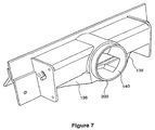
- FIG. 3 Also shown in Figure 3 is the rear opening 140 of the main body 12 which is the exit from suction chamber 56. It will be noted that the opening is defined by an attachment rim 200, which is sized and shaped to allow conventional fittings to be attached thereto. The exit or outlet from the main body is directed rearwardly. Thus, the exit can be easily joined to a short elbow fitting and plumbed to connect to vacuum piping whether coming from below or behind with equal ease.
- the front to back dimension of the unit is small enough to fit within a standard wall.
- the fitting not exceed four inches in depth and most preferably not more that about three inches.
- the inlet opening 40 it is preferred to have a relatively long compared to its height opening to draw the suction through.
- the rear it is preferred to have a circular exit to facilitate the connection of the fitting to vacuum piping.
- the transition must be made from the front opening to the rear opening over a compact body with a continuous top wall, side walls and bottom wall to form the suction chamber.
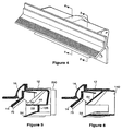
- FIG. 5 is a section along lines 5-5 in Figure 4, the vacuum chamber 56 extends upwardly and rearwardly from front opening 40.
- the vacuum chamber has a solid back wall 138 at the sides. Most preferably this back wall is also angled (see Figure 7) from back to front to encourage the flow of debris carried by suction to the rear exit 140.
- Figure 6 shows a section through the outlet 140, showing the vacuum chamber rising from the ramp under the partition 46 and out the outlet 140.
- the present invention provides an easy to make and install fitting which overcomes the disadvantages of the prior art.
- the device presents a covered front face which hides the internal workings of the device so that there is no need to have to clean or maintain the same.
- the configuration of the latch, holding the door member in a door covering position, while the spring 100 urges the door open, provides for a long lasting seal which is only compressed by the suction in the system.
Landscapes
- Pressure Vessels And Lids Thereof (AREA)
- Nozzles For Electric Vacuum Cleaners (AREA)
- Electric Vacuum Cleaner (AREA)
- Connector Housings Or Holding Contact Members (AREA)
- Quick-Acting Or Multi-Walled Pipe Joints (AREA)
Description
Claims (13)
- A vacuum fitting (10) for connection to a source of vacuum, said vacuum fitting (10) comprising:characterized in that said latch member (16) is selectively positionable to keep said closure (14) in said covering position when positioned between said main body (12) and said closure (14);a main body (12) mountable to a fixed structure, said main body (12) including an inlet opening (40) and an outlet opening (140);an openable closure (14) mounted to said main body (12) and being moveable between an open position and a position covering said inlet opening (40);a biaser (100) to urge said closure (14) to an open position;a switch (106,100,118) to initiate said remote source of vacuum when said closure (14) assumes said open position; and a latch member (16);
said latch member (16) permitting said closure (14) to move to an open position when not positioned between said main body (12) and said closure (14). - A vacuum fitting (10) according to Claim 1 wherein said openable closure (14) pivots about a horizontal axis, and said latch member (16) extends between a top of said main body (12) and a top of said openable closure (14) in said covering position.
- A vacuum fitting (10) according to any preceding claim wherein said openable closure (14) includes an edge against which said latch (16) catches.
- A vacuum fitting (10) according to any preceding claim wherein said latch member (16) is formed from a resilient material which is displaceable out of the path of said openable closure (14) to permit said openable closure (14) to pass thereby.
- A vacuum fitting (10) according to any preceding claim wherein said latch member (16) includes a stop element (90) for abutting said openable closure (14).
- A vacuum fitting (10) according to any preceding claim wherein said openable closure (14) includes a foot contacting surface (70) which includes an anti-slip feature (72).
- A vacuum fitting (10) according to Claim 6 wherein said anti-slip feature (72) comprises a roughened surface.
- A vacuum fitting (10) according to Claim 7 wherein said roughened surface comprises a plurality of ridges.
- A vacuum fitting (10) according to any preceding claim wherein said latch member (16) includes an outwardly extending toe tab (85).
- A vacuum fitting (10) according to Claim 9 as dependent upon Claim 5 wherein said latch member (16) is sufficiently resilient to allow a user to place a toe under said toe tab (85) and to lift said toe tab (85) enough to disengage said stop element (90) from said openable closure (14), and is mounted so that, when released, it returns to a position in the path of said openable closure (14).
- A vacuum fitting (10) according to any preceding claim wherein said biaser (100) is a spring including a hairpin section (114) for permitting early contact with an electrical connection (118) without creating a reaction force.
- A vacuum fitting (10) according to any preceding claim wherein said main body (12) has a rearwardly facing exit orifice (140) and a front to back distance of less than 10.16 cm (4 inches).
- A vacuum fitting (10) according to Claim 12 wherein said front to back width of said main body (12) is less than about 7.62 cm (3 inches).
Applications Claiming Priority (5)
| Application Number | Priority Date | Filing Date | Title |
|---|---|---|---|
| CA002279770A CA2279770C (en) | 1999-08-04 | 1999-08-04 | Vacuum fitting |
| CA2279770 | 1999-08-04 | ||
| US09/391,652 US6292977B1 (en) | 1999-09-07 | 1999-09-07 | Vacuum fitting |
| US391652 | 1999-09-07 | ||
| PCT/CA2000/000888 WO2001010281A1 (en) | 1999-08-04 | 2000-08-01 | Vacuum fitting |
Publications (2)
| Publication Number | Publication Date |
|---|---|
| EP1206208A1 EP1206208A1 (en) | 2002-05-22 |
| EP1206208B1 true EP1206208B1 (en) | 2003-06-25 |
Family
ID=25681114
Family Applications (1)
| Application Number | Title | Priority Date | Filing Date |
|---|---|---|---|
| EP00951151A Expired - Lifetime EP1206208B1 (en) | 1999-08-04 | 2000-08-01 | Vacuum fitting |
Country Status (6)
| Country | Link |
|---|---|
| EP (1) | EP1206208B1 (en) |
| KR (1) | KR100712400B1 (en) |
| AU (1) | AU760443B2 (en) |
| DE (1) | DE1206208T1 (en) |
| ES (1) | ES2186597T3 (en) |
| WO (1) | WO2001010281A1 (en) |
Families Citing this family (1)
| Publication number | Priority date | Publication date | Assignee | Title |
|---|---|---|---|---|
| DE102014002743B3 (en) * | 2013-05-13 | 2014-09-11 | Wilhelm Gronbach Gmbh | Integrated vacuum cleaner |
Family Cites Families (6)
| Publication number | Priority date | Publication date | Assignee | Title |
|---|---|---|---|---|
| US3676986A (en) * | 1969-09-15 | 1972-07-18 | Charles Woods | Built-in central vacuuming device |
| US5279016A (en) * | 1992-07-28 | 1994-01-18 | Klassen Timothy J | Vacuum outlet for built in vacuum |
| CA2105554C (en) * | 1993-09-03 | 2000-08-01 | James N. Smith | Waste disposal device |
| US5408721A (en) * | 1993-12-27 | 1995-04-25 | Wall; James C. | Automatic dustpan member for central vacuum cleaning system |
| US5504967A (en) * | 1994-03-03 | 1996-04-09 | Bernard J. Graham | Vacuum operated cleaning apparatus |
| CA2239535C (en) * | 1998-06-03 | 2006-11-21 | James N. Smith | Waste disposal device |
-
2000
- 2000-08-01 EP EP00951151A patent/EP1206208B1/en not_active Expired - Lifetime
- 2000-08-01 WO PCT/CA2000/000888 patent/WO2001010281A1/en not_active Ceased
- 2000-08-01 DE DE1206208T patent/DE1206208T1/en active Pending
- 2000-08-01 KR KR1020027001522A patent/KR100712400B1/en not_active Expired - Fee Related
- 2000-08-01 ES ES00951151T patent/ES2186597T3/en not_active Expired - Lifetime
- 2000-08-01 AU AU64202/00A patent/AU760443B2/en not_active Expired
Also Published As
| Publication number | Publication date |
|---|---|
| ES2186597T3 (en) | 2004-04-01 |
| KR20020068025A (en) | 2002-08-24 |
| DE1206208T1 (en) | 2003-05-28 |
| WO2001010281A1 (en) | 2001-02-15 |
| KR100712400B1 (en) | 2007-04-27 |
| EP1206208A1 (en) | 2002-05-22 |
| AU6420200A (en) | 2001-03-05 |
| AU760443B2 (en) | 2003-05-15 |
| ES2186597T1 (en) | 2003-05-16 |
Similar Documents
| Publication | Publication Date | Title |
|---|---|---|
| US6292977B1 (en) | Vacuum fitting | |
| CA2299564C (en) | Improved cleaning apparatus for central vacuum system | |
| US8819891B2 (en) | Floor inlet valve for a central vacuum cleaning system | |
| US6807707B2 (en) | Air exhaust structure for an upright-type vacuum cleaner | |
| CA2101484C (en) | Vacuum outlet for built in vacuum | |
| US5408721A (en) | Automatic dustpan member for central vacuum cleaning system | |
| US6108858A (en) | Waste receptacle for a vacuum cleaning system | |
| CA2817246C (en) | Vacuum assembly | |
| US8631817B2 (en) | Central vacuum inlet valve assembly | |
| US3706184A (en) | Wall-recessed suction cleaner | |
| AU760443B2 (en) | Vacuum fitting | |
| CA2279770C (en) | Vacuum fitting | |
| EP2129273B1 (en) | Inlet device for central vacuum system | |
| WO1990010777A1 (en) | A slot valve for slot openings in walls or window frames | |
| CA2105554C (en) | Waste disposal device | |
| CA2239535C (en) | Waste disposal device | |
| CN222917466U (en) | Carpet cleaning machine | |
| KR960016447B1 (en) | Mop installation device for commercial inlet of vacuum cleaner | |
| JPS6041893Y2 (en) | vacuum cleaner | |
| JPH0232215Y2 (en) | ||
| JPH08317886A (en) | Suction tool for floor | |
| JPH0729078U (en) | Western style toilet | |
| WO2010112987A1 (en) | Improvement on inlet device for central vacuum system | |
| JPH06319672A (en) | Vacuum cleaner |
Legal Events
| Date | Code | Title | Description |
|---|---|---|---|
| PUAI | Public reference made under article 153(3) epc to a published international application that has entered the european phase |
Free format text: ORIGINAL CODE: 0009012 |
|
| 17P | Request for examination filed |
Effective date: 20020304 |
|
| AX | Request for extension of the european patent |
Free format text: AL;LT;LV;MK;RO;SI |
|
| GRAH | Despatch of communication of intention to grant a patent |
Free format text: ORIGINAL CODE: EPIDOS IGRA |
|
| EL | Fr: translation of claims filed | ||
| GRAH | Despatch of communication of intention to grant a patent |
Free format text: ORIGINAL CODE: EPIDOS IGRA |
|
| GRAA | (expected) grant |
Free format text: ORIGINAL CODE: 0009210 |
|
| DET | De: translation of patent claims | ||
| AK | Designated contracting states |
Designated state(s): AT BE CH CY DE DK ES FI FR GB GR IE IT LI LU MC NL PT SE |
|
| PG25 | Lapsed in a contracting state [announced via postgrant information from national office to epo] |
Ref country code: NL Free format text: LAPSE BECAUSE OF FAILURE TO SUBMIT A TRANSLATION OF THE DESCRIPTION OR TO PAY THE FEE WITHIN THE PRESCRIBED TIME-LIMIT Effective date: 20030625 Ref country code: BE Free format text: LAPSE BECAUSE OF FAILURE TO SUBMIT A TRANSLATION OF THE DESCRIPTION OR TO PAY THE FEE WITHIN THE PRESCRIBED TIME-LIMIT Effective date: 20030625 Ref country code: CH Free format text: LAPSE BECAUSE OF FAILURE TO SUBMIT A TRANSLATION OF THE DESCRIPTION OR TO PAY THE FEE WITHIN THE PRESCRIBED TIME-LIMIT Effective date: 20030625 Ref country code: AT Free format text: LAPSE BECAUSE OF FAILURE TO SUBMIT A TRANSLATION OF THE DESCRIPTION OR TO PAY THE FEE WITHIN THE PRESCRIBED TIME-LIMIT Effective date: 20030625 Ref country code: LI Free format text: LAPSE BECAUSE OF FAILURE TO SUBMIT A TRANSLATION OF THE DESCRIPTION OR TO PAY THE FEE WITHIN THE PRESCRIBED TIME-LIMIT Effective date: 20030625 |
|
| REG | Reference to a national code |
Ref country code: GB Ref legal event code: FG4D |
|
| REG | Reference to a national code |
Ref country code: CH Ref legal event code: EP |
|
| REG | Reference to a national code |
Ref country code: IE Ref legal event code: FG4D |
|
| REF | Corresponds to: |
Ref document number: 60003563 Country of ref document: DE Date of ref document: 20030731 Kind code of ref document: P |
|
| PG25 | Lapsed in a contracting state [announced via postgrant information from national office to epo] |
Ref country code: CY Free format text: LAPSE BECAUSE OF FAILURE TO SUBMIT A TRANSLATION OF THE DESCRIPTION OR TO PAY THE FEE WITHIN THE PRESCRIBED TIME-LIMIT Effective date: 20030801 Ref country code: LU Free format text: LAPSE BECAUSE OF NON-PAYMENT OF DUE FEES Effective date: 20030801 |
|
| REG | Reference to a national code |
Ref country code: SE Ref legal event code: TRGR |
|
| PG25 | Lapsed in a contracting state [announced via postgrant information from national office to epo] |
Ref country code: MC Free format text: LAPSE BECAUSE OF NON-PAYMENT OF DUE FEES Effective date: 20030831 |
|
| PG25 | Lapsed in a contracting state [announced via postgrant information from national office to epo] |
Ref country code: GR Free format text: LAPSE BECAUSE OF FAILURE TO SUBMIT A TRANSLATION OF THE DESCRIPTION OR TO PAY THE FEE WITHIN THE PRESCRIBED TIME-LIMIT Effective date: 20030925 Ref country code: DK Free format text: LAPSE BECAUSE OF FAILURE TO SUBMIT A TRANSLATION OF THE DESCRIPTION OR TO PAY THE FEE WITHIN THE PRESCRIBED TIME-LIMIT Effective date: 20030925 |
|
| LTIE | Lt: invalidation of european patent or patent extension |
Effective date: 20030625 |
|
| NLV1 | Nl: lapsed or annulled due to failure to fulfill the requirements of art. 29p and 29m of the patents act | ||
| REG | Reference to a national code |
Ref country code: CH Ref legal event code: PL |
|
| REG | Reference to a national code |
Ref country code: ES Ref legal event code: FG2A Ref document number: 2186597 Country of ref document: ES Kind code of ref document: T3 |
|
| ET | Fr: translation filed | ||
| PLBE | No opposition filed within time limit |
Free format text: ORIGINAL CODE: 0009261 |
|
| STAA | Information on the status of an ep patent application or granted ep patent |
Free format text: STATUS: NO OPPOSITION FILED WITHIN TIME LIMIT |
|
| 26N | No opposition filed |
Effective date: 20040326 |
|
| PGFP | Annual fee paid to national office [announced via postgrant information from national office to epo] |
Ref country code: IE Payment date: 20060814 Year of fee payment: 7 |
|
| REG | Reference to a national code |
Ref country code: IE Ref legal event code: MM4A |
|
| PG25 | Lapsed in a contracting state [announced via postgrant information from national office to epo] |
Ref country code: IE Free format text: LAPSE BECAUSE OF NON-PAYMENT OF DUE FEES Effective date: 20070801 |
|
| PGFP | Annual fee paid to national office [announced via postgrant information from national office to epo] |
Ref country code: DE Payment date: 20080814 Year of fee payment: 9 |
|
| PGFP | Annual fee paid to national office [announced via postgrant information from national office to epo] |
Ref country code: FI Payment date: 20080815 Year of fee payment: 9 Ref country code: IT Payment date: 20080828 Year of fee payment: 9 |
|
| PGFP | Annual fee paid to national office [announced via postgrant information from national office to epo] |
Ref country code: SE Payment date: 20080807 Year of fee payment: 9 |
|
| PG25 | Lapsed in a contracting state [announced via postgrant information from national office to epo] |
Ref country code: FI Free format text: LAPSE BECAUSE OF NON-PAYMENT OF DUE FEES Effective date: 20090801 |
|
| PG25 | Lapsed in a contracting state [announced via postgrant information from national office to epo] |
Ref country code: DE Free format text: LAPSE BECAUSE OF NON-PAYMENT OF DUE FEES Effective date: 20100302 |
|
| PGFP | Annual fee paid to national office [announced via postgrant information from national office to epo] |
Ref country code: ES Payment date: 20100915 Year of fee payment: 11 |
|
| PGFP | Annual fee paid to national office [announced via postgrant information from national office to epo] |
Ref country code: FR Payment date: 20100824 Year of fee payment: 11 |
|
| PGFP | Annual fee paid to national office [announced via postgrant information from national office to epo] |
Ref country code: PT Payment date: 20100721 Year of fee payment: 11 |
|
| PG25 | Lapsed in a contracting state [announced via postgrant information from national office to epo] |
Ref country code: IT Free format text: LAPSE BECAUSE OF NON-PAYMENT OF DUE FEES Effective date: 20090801 |
|
| PG25 | Lapsed in a contracting state [announced via postgrant information from national office to epo] |
Ref country code: SE Free format text: LAPSE BECAUSE OF NON-PAYMENT OF DUE FEES Effective date: 20090802 |
|
| REG | Reference to a national code |
Ref country code: PT Ref legal event code: MM4A Free format text: LAPSE DUE TO NON-PAYMENT OF FEES Effective date: 20120201 |
|
| REG | Reference to a national code |
Ref country code: FR Ref legal event code: ST Effective date: 20120430 |
|
| PG25 | Lapsed in a contracting state [announced via postgrant information from national office to epo] |
Ref country code: PT Free format text: LAPSE BECAUSE OF NON-PAYMENT OF DUE FEES Effective date: 20120201 |
|
| PG25 | Lapsed in a contracting state [announced via postgrant information from national office to epo] |
Ref country code: FR Free format text: LAPSE BECAUSE OF NON-PAYMENT OF DUE FEES Effective date: 20110831 |
|
| REG | Reference to a national code |
Ref country code: ES Ref legal event code: FD2A Effective date: 20130605 |
|
| PG25 | Lapsed in a contracting state [announced via postgrant information from national office to epo] |
Ref country code: ES Free format text: LAPSE BECAUSE OF NON-PAYMENT OF DUE FEES Effective date: 20110802 |
|
| PGFP | Annual fee paid to national office [announced via postgrant information from national office to epo] |
Ref country code: GB Payment date: 20190731 Year of fee payment: 20 |
|
| REG | Reference to a national code |
Ref country code: GB Ref legal event code: PE20 Expiry date: 20200731 |
|
| PG25 | Lapsed in a contracting state [announced via postgrant information from national office to epo] |
Ref country code: GB Free format text: LAPSE BECAUSE OF EXPIRATION OF PROTECTION Effective date: 20200731 |