EP1206137A1 - Optical disk, optical disk recording/reproducing apparatus, and recording/reproducing method - Google Patents
Optical disk, optical disk recording/reproducing apparatus, and recording/reproducing method Download PDFInfo
- Publication number
- EP1206137A1 EP1206137A1 EP00946337A EP00946337A EP1206137A1 EP 1206137 A1 EP1206137 A1 EP 1206137A1 EP 00946337 A EP00946337 A EP 00946337A EP 00946337 A EP00946337 A EP 00946337A EP 1206137 A1 EP1206137 A1 EP 1206137A1
- Authority
- EP
- European Patent Office
- Prior art keywords
- data
- channel
- recorded
- video data
- optical disk
- Prior art date
- Legal status (The legal status is an assumption and is not a legal conclusion. Google has not performed a legal analysis and makes no representation as to the accuracy of the status listed.)
- Withdrawn
Links
Images






Classifications
-
- H—ELECTRICITY
- H04—ELECTRIC COMMUNICATION TECHNIQUE
- H04N—PICTORIAL COMMUNICATION, e.g. TELEVISION
- H04N9/00—Details of colour television systems
- H04N9/79—Processing of colour television signals in connection with recording
- H04N9/80—Transformation of the television signal for recording, e.g. modulation, frequency changing; Inverse transformation for playback
- H04N9/82—Transformation of the television signal for recording, e.g. modulation, frequency changing; Inverse transformation for playback the individual colour picture signal components being recorded simultaneously only
- H04N9/8205—Transformation of the television signal for recording, e.g. modulation, frequency changing; Inverse transformation for playback the individual colour picture signal components being recorded simultaneously only involving the multiplexing of an additional signal and the colour video signal
- H04N9/8227—Transformation of the television signal for recording, e.g. modulation, frequency changing; Inverse transformation for playback the individual colour picture signal components being recorded simultaneously only involving the multiplexing of an additional signal and the colour video signal the additional signal being at least another television signal
-
- G—PHYSICS
- G11—INFORMATION STORAGE
- G11B—INFORMATION STORAGE BASED ON RELATIVE MOVEMENT BETWEEN RECORD CARRIER AND TRANSDUCER
- G11B20/00—Signal processing not specific to the method of recording or reproducing; Circuits therefor
- G11B20/00007—Time or data compression or expansion
-
- H—ELECTRICITY
- H04—ELECTRIC COMMUNICATION TECHNIQUE
- H04N—PICTORIAL COMMUNICATION, e.g. TELEVISION
- H04N5/00—Details of television systems
- H04N5/76—Television signal recording
- H04N5/91—Television signal processing therefor
- H04N5/92—Transformation of the television signal for recording, e.g. modulation, frequency changing; Inverse transformation for playback
- H04N5/9201—Transformation of the television signal for recording, e.g. modulation, frequency changing; Inverse transformation for playback involving the multiplexing of an additional signal and the video signal
- H04N5/9205—Transformation of the television signal for recording, e.g. modulation, frequency changing; Inverse transformation for playback involving the multiplexing of an additional signal and the video signal the additional signal being at least another television signal
-
- H—ELECTRICITY
- H04—ELECTRIC COMMUNICATION TECHNIQUE
- H04N—PICTORIAL COMMUNICATION, e.g. TELEVISION
- H04N5/00—Details of television systems
- H04N5/76—Television signal recording
- H04N5/84—Television signal recording using optical recording
- H04N5/85—Television signal recording using optical recording on discs or drums
-
- H—ELECTRICITY
- H04—ELECTRIC COMMUNICATION TECHNIQUE
- H04N—PICTORIAL COMMUNICATION, e.g. TELEVISION
- H04N5/00—Details of television systems
- H04N5/76—Television signal recording
- H04N5/91—Television signal processing therefor
- H04N5/92—Transformation of the television signal for recording, e.g. modulation, frequency changing; Inverse transformation for playback
- H04N5/926—Transformation of the television signal for recording, e.g. modulation, frequency changing; Inverse transformation for playback by pulse code modulation
- H04N5/9261—Transformation of the television signal for recording, e.g. modulation, frequency changing; Inverse transformation for playback by pulse code modulation involving data reduction
-
- H—ELECTRICITY
- H04—ELECTRIC COMMUNICATION TECHNIQUE
- H04N—PICTORIAL COMMUNICATION, e.g. TELEVISION
- H04N9/00—Details of colour television systems
- H04N9/79—Processing of colour television signals in connection with recording
- H04N9/7921—Processing of colour television signals in connection with recording for more than one processing mode
-
- H—ELECTRICITY
- H04—ELECTRIC COMMUNICATION TECHNIQUE
- H04N—PICTORIAL COMMUNICATION, e.g. TELEVISION
- H04N9/00—Details of colour television systems
- H04N9/79—Processing of colour television signals in connection with recording
- H04N9/80—Transformation of the television signal for recording, e.g. modulation, frequency changing; Inverse transformation for playback
- H04N9/804—Transformation of the television signal for recording, e.g. modulation, frequency changing; Inverse transformation for playback involving pulse code modulation of the colour picture signal components
- H04N9/8042—Transformation of the television signal for recording, e.g. modulation, frequency changing; Inverse transformation for playback involving pulse code modulation of the colour picture signal components involving data reduction
-
- H—ELECTRICITY
- H04—ELECTRIC COMMUNICATION TECHNIQUE
- H04N—PICTORIAL COMMUNICATION, e.g. TELEVISION
- H04N9/00—Details of colour television systems
- H04N9/79—Processing of colour television signals in connection with recording
- H04N9/80—Transformation of the television signal for recording, e.g. modulation, frequency changing; Inverse transformation for playback
- H04N9/804—Transformation of the television signal for recording, e.g. modulation, frequency changing; Inverse transformation for playback involving pulse code modulation of the colour picture signal components
- H04N9/806—Transformation of the television signal for recording, e.g. modulation, frequency changing; Inverse transformation for playback involving pulse code modulation of the colour picture signal components with processing of the sound signal
- H04N9/8063—Transformation of the television signal for recording, e.g. modulation, frequency changing; Inverse transformation for playback involving pulse code modulation of the colour picture signal components with processing of the sound signal using time division multiplex of the PCM audio and PCM video signals
Definitions
- the system controller 13 transfers information on the channels that is to be recorded in units of a frame (for example, in the case shown in Fig. 1, information that the individual channels are uniformly recorded in every three frames) to a record-channel determining circuit 15.
- the record-channel determining circuit 15 outputs a gate signal for only an interval of frame of the channel determined in units of a frame.
- the gate signal is used to control the multiplexer 17, and only video signals of the channels to be recorded are selectively output through the multiplexer 17.
- the playback-channel-time-division selection circuit 25 is controlled to select only a video channel signal desired to be reproduced and output.
- Data arrays of video and audio data of the playback-channel selected and output as described above are formed as shown in Figs. 1E, 1F, and 1G.
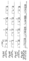
- Figs. 3A to 3G are explanatory views regarding an optical disk recording method and optical disk record formats according to Embodiment 2.
- the amount of selected-channel video data recorded within the unit frame time is substantially M/N.
- the audio data that is synchronous with the video data is arranged and recorded as shown in Fig. 5D. Specifically, the audio data is not compressed in any frames, and is recorded as in the data amount when decoded.
- the video data can be recorded substantially at a constant recording rate, regardless of the number of the selected video channels.
- the video and audio data selected by the playback-channel-time-division selection circuit 25 is separated by a video/audio-playback-frame separating circuit 26 into audio data and video data.
- the audio data separated and output is decoded by an audio decoding circuit 27.
- the decoded data is converted into an audio signal through an audio-signal processing circuit 28 and the audio signal is output from a speaker 29.
- the video data is decoded, and the decoded data is reproduced by a video decoding circuit 30 on a monitor 32 through a video-signal processing circuit 31.
- the video data is decoded by the video decoding circuit 30 after decompressed according to the compression-ratio information included in the video data.
- the audio data is not decompressed since it has not been compressed.
- the movie program on one channel is reproduced with a higher quality than music programs on other two channels.
- video data is recorded on track 1 of the optical disk by making the compression ratio for the video data on the a-channel lower than ratios for the video data on the other channels.
- the data compression ratios are set so that the record data amount of the a-channel is twice the record data amount of the b- channel or the c-channel.
- Va1 and Aa1 in the first frame Va2 and Aa2 in the second frame, Va3 and Aa3 in the third frame, and Va4 and Aa4 in the fourth frame are selected respectively and reproduced sequentially and intermittently. Then, the video data is decompressed and decoded.
- the audio data can be decoded without decompression since the audio data is not compressed at the recording step.
- the a-channel since the a-channel has the data amount twice as much as the data amount of the other b- or c-channel, the a-channel can be reproduced with a higher video quality.
- the total amount of video data Va1 to Van and audio data Aa1 to Aan for a period up to the broadcast-program end time is maintained less than or equal to a remaining data capacity 5 of the optical disk.
- Fig. 10D shows an example case where the video data in the a-channel is thinned out and recorded on every six frames, that is, Va4, Va10, Va16, ... are thinned out (or reduced). In this case, the audio data is not reduced.
- the a-channel is recorded at every six frames, and the data in each of the b-channel and the c-channel is recorded at every three frames.
Landscapes
- Engineering & Computer Science (AREA)
- Signal Processing (AREA)
- Multimedia (AREA)
- Signal Processing For Digital Recording And Reproducing (AREA)
- Optical Recording Or Reproduction (AREA)
Abstract
A recording method of the invention is for time-division
multiplexing and recording N channels of video
data such as broadcasting onto an optical disk. In the
method, a data compression ratio for video data on each
channel is determined so that a total amount of data on N
channels to be recorded in unit time is substantially
constant regardless of the number (N) of channels. Then,
the data is compressed at the compression ratio to be
recorded. Alternately, in the method, the video data is
recorded onto an optical disk by a method in which
intervals of frames to be recorded is determined so that a
total amount of data on the N channels to be recorded in a
unit time becomes substantially constant regardless of the
number of channels (N). Then, the frames on each channel
are thinning out to cause intervals of the frame to become
the determined intervals of frames, resulting in recording
of the video data on each channel onto the optical disk.
Description
The present invention relates to an optical disk
on which multi-channel video information is multiplexed
and recorded, and further to a method and an apparatus for
multiplexing multi-channel video information and recording
it onto the optical disk.
Optical disks such as DVD-RAMs are expected to be
widely usable as mass storage devices in multimedia
applications. The optical disks can be used as media that
replace conventional videotapes to record received
broadcast programs.
In a background in which the digital broadcasting
would be increasingly used in the future, it is expected
that the optical disk would be used to synchronously
receive multi-channel programs and to synchronously record
multi-channel programs.
An optical disk for recording video information
has a track structure as shown in Fig. 12. An optical disk
6 is formed of a material such as polycarbonate, and has a
track 1 formed to have a structure including a spiral
concave groove. The optical disk having such the structure
has a recording film formed thereon. A laser beam is
radiated onto the recording film to record information in
the form of record marks. More specifically, while
tracking servo is applied, video data and audio data in the
video information are thereby sequentially arranged and
recorded onto the track 1.
The track 1 has a recording field partitioned in
a plurality of sector fields 7 each having a specific
length of data field in which video information is to be
recorded. On the top of each of the sector field 7, an
address field 8 is prearranged with, for example, convex
and concave portions and embossed pits of a groove.
An example conceivable as a method of performing
video-recording for multi-channel broadcast programs on the
track 1 of the above-described optical disk 6 will
hereinbelow be described with reference to Figs. 11A to 11H.
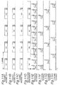
Figs. 11A to 11H are explanatory views showing a
method of recording video information onto an optical disk,
and a recording format. In more specific, Figs. 11A to 11H
explains an example case where video information in
broadcast programs of three selected channels (a-channel,
b-channel and c-channel) is synchronously recorded onto an
optical disk.
Fig. 11A shows a state where video information in
the selected a-channel is encoded to blocks each
representing a data signal in units of frames. Figs. 11B
and 11C also show states where video information on the
individual selected channels is encoded to blocks each
representing one-frame-unit data signal.
Regarding the notation of "Xyz" in Figs. 11A to
11H, the first symbol "X" represents video data when it is
"V", and represents audio data when it is "A". The second
symbol "y" represents a y-channel broadcast program, and
the last symbol "z" represents a z-th frame. For example,
"Va1" represents video data in a first frame of the a-channel.
Similarly, "Aa1" represents audio data in the
first frame of the a-channel.
Figs. 11A, 11B, and 11C show time sequences of
encoded video data and audio data on the respective a-channel,
b-channel, and c-channel.
Ordinary recording is performed through a single
record head, that is, one-channel record head. Hence, the
following method of recording data by performing time-wise
multiplexing when synchronously recording three channels.
In specific, all the blocks of data encoded in units of
each channel as shown in Figs. 11A, 11B, and 11C are
sequentially arranged in time series on the same time axis.
For example, as shown in Fig. 11D, video data and audio
data are arranged in the order of Va1/Aa1, Vb1/Ab1, Vc1/Ac1,
Va2/Aa2,···.
However, in such a simple sequential time-series
arrangement of the three-channel data, the amount of data
to be recorded per unit time increases three times, and
hence the data cannot be recorded in the optical disk at a
recording data rate as it is. To implement such recording,
the receding data rate of an optical disk device must be
heightened substantially three times to complete a
recording operation for the three-channel data within a
one-frame time (Such the recording operation hereinbelow
will be referred to as a "triple-rate recording
operation".). In specific, as shown in Fig. 11E, the
recording rate is increased substantially three times, and
the data is sequentially recorded onto the track 1 of the
optical disk 6.
The three-channel video data and audio data thus
recorded are reproduced as follows. When three-channel
data is recorded in the manner of triple-rate recording
operation, reproduction (playback) operation has to be done
at the triple rate. For example, as shown in Fig. 11F, to
reproduce (play back) the a-channel, only the data in
Va1/Aa1, Va2/Aa2, Va3/Aa3, and Va4/Aa4 need to be selected
and reproduced sequentially and intermittently at the
triple rate. Similarly, as shown in Fig. 11G, to reproduce
the b-channel, only the data in Vb1/Ab1, Vb2/Ab2, Vb3/Ab3,
and Vb4/Ab4 need to be selected and reproduced sequentially
and intermittently at the triple rate. Similarly, as shown
in Fig. 11H, to reproduce the b-channel, only the data in
Vc1/Ac1, Vc2/Ac2, Vc3/Ac3, and Vc4/Ac4 need to be selected
and reproduced sequentially and intermittently at the
triple rate.
With the configuration as described above, as the
number of selected channels for video information increases,
data rate of reproducing the optical disk device needs to
be increased by the channel-number multiple. This requires
a mechanism dedicated for driving an optical disk at a high
speed as well as an optical disk having a property capable
of performing high-rate recording. Generally, increase in
recording data rate of an optical disk device requires
complicated configuration elements of the apparatus, and
causes the manufacturing cost to raise. Because of those
factors and the nature of the recording material for the
optical disk, the increase of recording data rate cannot
easily be implemented.
In view of the above-described problems, the
present invention is directed to provide an optical disk
recording/reproducing method, an optical disk recording/reproducing
apparatus, and an optical disk in which video
information on selected N channels (N is an integer) can be
recorded/reproduced at a constantly maintained recording/reproducing
data rate of an optical disk device.
A recording method according to the present
invention is a method of recording video data on N (N is an
integer) channels synchronously onto an optical disk, in
which the video data is formed of a time series of video
frames. The method comprises: determining a compression
ratio for each channel so that a total data amount for the
N channels of video data after compression that is recorded
during a record time T is less than or equal to a data
amount that can be recorded at a maximum recording rate of
the optical disk during the record time T; compressing the
video data in units of frames in each channel at the
determined compression ratio; and recording the compressed
data onto the optical disk. The record time T being a
minimum time of record times individually comprising at
least one video frame for each channel. The video data is
recorded onto the optical disk so that a total amount of
data on the N channels to be recorded in a unit time is
substantially constant regardless of the number of channels
to be recorded.
In the method, the compression ratio for the
video data on each channel may be set to 1/N.
The method may further comprise determining an
allocation ratio of the data amount to be recorded for each
channel in the record time T to all data to be recorded in
the record time T according to contents of the video data
on each channel. In this case, the compression ratio for
each channel may be determined according to the determined
allocation ratio.
In the method, when the video data to be recorded
includes attribute data indicating the contents of the
video data, the attribute data may be detected from the
video data. The contents of the video data on each channel
may be determined according to the detected attribute data.
In the method, when the video data on each
channel is accompanied by audio data synchronizing
therewith, the determining may determine the compression
ratio for the video data on each channel so that a total
data amount for N channels of video and audio data after
compression that is recorded during the record time T is
substantially constant regardless of the input number of
channels. The method may comprise arranging the video
compressed at the determined compression ratio and audio
data into each frame in a predetermined order, to thereby
record the data onto the optical disk.
When the individual video data on the N channels
(N is an integer) in the predetermined record time is to be
synchronously recorded onto the optical disk, the method
may further comprise computing a total data amount of video
data on the N channels to be recorded in the predetermined
record time, and a capacity of free area of the optical
disk in which data can be recorded. In this case, the
compression ratio may be determined so that the total
amount of data to be recorded is less than or equal to the
capacity of free area of the optical disk in which data can
be recorded.
An another recording method according to the
invention is a method of recording video data of N (N is an
integer) channels synchronously onto an optical disk, in
which the video data is formed of a time series of video
frames. The method comprises: selecting one of the N
channels in units of video frames, as a channel of which
video data is recorded; and recording the video data in the
video frame on the selected channel onto the optical disk.
N channels of the video data are time-division multiplexed
in units of video frames and recorded onto the optical disk.
In the above another method, when each of the
video data on the N channels (N is an integer) in a
predetermined record time is to be synchronously recorded
onto the optical disk. The method comprises: computing a
total data amount for the N channels of video data to be
recorded in the predetermined record time, and a capacity
of free area of the optical disk in which data can be
recorded; comparing the total data amount to be recorded
with the capacity of free area of the optical disk; and
determining, when the total data amount to be recorded is
greater than the capacity amount of the optical disk, the
number of the video frames to be recorded in a
predetermined time so that in at least one of the N
channels the total data amount to be recorded is less than
or equal to the capacity of free are of the optical disk.
A reproducing method according to the invention
is a method of reproducing recorded data from an optical
disk onto which N channels (N is an integer) of video data
are compressed at a predetermined compression ratio and
arranged in a predetermined channel order to thereby be
recorded. The method comprises: inputting information for
designating a channel to be reproduced; reading data from
the optical disk in units of frames; reproducing video data
on the designated channel to be reproduced from the video
data recorded in the read frame, after the video data is
decompressed; and reproducing audio data that is included
in the read frame and is on the channel to be recorded.
An another reproducing method according to the
invention is a method of reproducing recorded data from an
optical disk having an area in which video data on N
channels (N is an integer) is recorded in units of frames
by a time-division multiplexing method. The optical disk
stores the video data selected in every predetermined
number of frames on one channel, and audio data on all
channels continuous to the video data. The method
comprising: inputting information for designating a channel
to be reproduced; reading data from the optical disk in
units of frames; and if video data included in the read
frame is video data of designated channel to be reproduced,
then reproducing the video data, and further reproducing
audio data that is included in the read frame and is on the
designated channel to be recorded.
An optical disk according to the invention is an
optical disk having an area in which video data on N
channels (N is an integer) are recorded in units of frames
by a time-division multiplexing method. The disk comprises
a frame area which is provided corresponding to a video
frame series in one channel and in which video data on each
channel is multiplexed and recorded in units of video
frames. The frame area has a data length equal to a total
for N channels of data length in one frame of video data
which is compressed at a predetermined compression ratio.
The predetermined compression ratio is determined so that a
total data amount for the N channels of video data to be
recorded during a record time T is less than or equal to a
data amount that can be recorded during the record time T
at a maximum recording rate of the optical disk. The
record time T is a minimum time in record times
individually including at least one video frame for each
channel.
An another optical disk according to the
invention is an optical disk having an area in which video
data of N (N is an integer) channels are recorded
synchronously onto an optical disk. The video data is
formed of a time series of video frames. One of the N
channels is selected as a channel of which video data is to
be recorded, in units of video frames. An area for
recording the video data in the video frame on the selected
channel onto the optical disk is arranged on a track of the
optical disk.
A recording apparatus according to the invention
is an apparatus for recording video data on N (N is an
integer) channels synchronously onto an optical disk, the
video data formed of a time series of video frames. The
apparatus comprises: a section that determines a
compression ratio for each channel so that a total data
amount for the N channels of video data after compression
that is recorded during a record time T is less than or
equal to a data amount that can be recorded at a maximum
recording rate of the optical disk during the record time
T; a section that compresses the video data in units of
frames in each channel at the determined compression ratio;
and a section that records the compressed data onto the
optical disk. The record time T is a minimum time of
record times individually comprising at least one video
frame for each channel. The video data is recorded onto
the optical disk so that a total amount of data on the N
channels to be recorded in a unit time is substantially
constant regardless of the number of channels to be
recorded.
An another recording apparatus according to the
invention is an apparatus for recording video data of N (N
is an integer) channels synchronously onto an optical disk.
The video data is formed of a time series of video frames.
The apparatus comprises: a section that selects one of the
N channels in units of video frames, as a channel of which
video data is recorded; and a section that records the
video data in the video frame on the selected channel onto
the optical disk. N channels of the video data are time-division
multiplexed in units of video frames and recorded
onto the optical disk.
A reproducing apparatus according to the
invention is an apparatus for reproducing recorded data
from an optical disk onto which N channels (N is an
integer) of video data are compressed at a predetermined
compression ratio and arranged in a predetermined channel
order to thereby be recorded. The apparatus comprises: a
section that inputs information for designating a channel
to be reproduced; a section that reads data from the
optical disk in units of frames; and a section that
reproduces video data on the designated channel to be
reproduced from the video data recorded in the read frame,
after the video data is decompressed, and audio data that
is included in the read frame and is on the channel to be
recorded.
An another reproducing apparatus according to the
invention is an apparatus for reproducing recorded data
from an optical disk having an area in which video data on
N channels (N is an integer) is recorded in units of frames
by a time-division multiplexing method. The optical disk
stores the video data selected in every predetermined
number of frames on one channel, and audio data on all
channels continuous to the video data. The apparatus
comprises: a section that inputs information for
designating a channel to be reproduced; a section that
reads data from the optical disk in units of frames; and a
section that, if video data included in the read frame is
video data of designated channel to be reproduced, then
reproduces the video data, and audio data that is included
in the read frame and is on the designated channel to be
recorded.
According to the present invention, regardless of
the number of selected video channels, video data on an
arbitrary number of channels can be recorded onto an
optical disk at a recording rate of the optical disk that
is substantially fixedly maintained. In addition, at a
recording rate of the optical disk that is substantially
fixedly maintained, video data on an arbitrary number of
channels can be recorded on the optical disk; moreover,
depending on the contents of video information, a specific
channel desired by a viewer/listener can be
recorded/reproduced to produce higher video quality.
Moreover, video data on an arbitrary number of channels as
well as audio data that less deteriorates in audio quality
can be recorded on the optical disk. Furthermore,
regardless of a remaining data capacity, video data on
selected multiple video channels can be recorded in a
period up to the end of broadcast program.
Hereinbelow, preferred embodiments of an optical
disk and an optical disk recording/reproducing apparatus
according to the present invention will be described with
reference to the accompanying drawings.
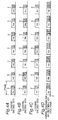
Figs. 1A to 1G are explanatory views of a
recording method and a data arrangement on an optical disk
according to Embodiment 1 of the present invention.
These figures are explanatory regarding a method
of selecting video information in three-channel programs
from broadcast programs and recording the video information
onto an optical disk loaded into an optical disk device in
which the recording rate and the reproducing rate are fixed.
Fig. 1A shows a state where video information on
a selected a-channel is encoded to blocks each representing
data signal in units of frames. Figs. 1B and 1C also show
states where video information on the individual selected
channels is encoded to blocks each representing one-screen-unit.
In the notation of "Xyz" in Figs. 1A to 1G, "V"
shown as the first symbol "X" represents video data, and
"A" shown as the first symbol represents audio data. The
second symbol "y" represents a y-channel broadcast program,
and the last symbol "z" represents a z-th frame. For
example, "Va1" represents video data in a first frame of
the a-channel. Similarly, "Aa1" represents audio data in
the first frame of the a-channel. (The above notation
manner is the same or similar in embodiments described
below).
The optical disk of the present embodiment has a
track structure that is similar to that of the conventional
optical disk shown in Fig. 12.
Hereinbelow, a description will be made regarding
a recording method of the present embodiment in which the
video data Vxy and the audio data Axy shown in Figs. 1A to
1G are arranged and recorded onto an optical disk 6 having
the track structure as shown in Fig. 12.
Fig. 1D is an explanatory view showing a
processing state in the recording method of the present
embodiment. As shown in the figure, a channel having data
to be recorded onto the optical disk is determined from
selected three channels, and video data on the determined
channel and audio data on all the selected channels are
arranged and recorded within a one-frame time onto the
track 1 of the optical disk 1.
For example, video data Va1 on the a-channel in a
first frame is determined as video data to be recorded, and
the video data Va1 is arranged and recorded within the time
zone onto the first frame on the track 1 of the optical
disk. Subsequently, video data Vb2 on the b-channel in a
second frame is determined as video data to be recorded,
and the video data Vb2 is arranged and recorded within the
time zone of the second frame on the track 1 of the optical
disk. Furthermore, video data Vc3 on the c-channel in a
third frame is determined as video data to be recorded, and
the video data Vc3 is arranged and recorded within the time
zone of the third frame on the track 1 of the optical disk.
In a fourth frame, in which one circle of the
operations has been completed, video data Va4 on the a-channel
is determined, and the video data Va4 is arranged
and recorded within the time zone of the fourth frame on
the track 1 of the optical disk.
Similarly, the b-channel is determined in a fifth
frame, the c-channel is determined in a sixth frame, and a-channel
is determined in a seventh frame. Then, video data
on each of the determined channels is arranged (time-division
multiplexed) and recorded within the time zone of
the respective frame on the track 1 of the optical disk.
As described, when video data on three channels
are to be selected and recorded, video data on specific
channels is recorded onto the track 1 of the optical disk
on a basis of three frames.
More specifically, in the method of determining
the video channel in each of the frames, video data. on a C-th
channel in video information on selected N channels is
arranged and recorded at a (mN+C)-th frame within a one-frame
time length field of the track of the optical disk,
where "m" is "0" or an integer, and "C" is an integer that
is equal to 1 or larger and is equal to N or smaller.
As in the above-described case where recording is
performed by determining one specific video channel in each
frame, the recording can be implemented substantially at a
fixed recording rate of the optical disk regardless of the
number of selected channels.
Further, regarding audio data synchronizing with
frame-unit video data, audio data on all the channels is
recorded in each frame regardless of the determined video
channels in each frame. The reason thereof is that when
audio data is intermittently or reductively recorded as is
done for video data, original audio data cannot be
reproduced or played back.
For example, the audio data synchronizing with
the video data Va1 on the a-channel is Aa1, the audio data
synchronizing with the video data Vb1 on the b-channel is
Ab1, and the audio data synchronizing with the video data
Vc1 on the a-channel is Ac1.
The audio data that have thus synchronized are
arranged and recorded as shown in Fig. 1D. In specific, in
the first frame, while the a-channel is determined for
video data, audio data Aa1, Ab1, and Ac1 on all the
channels are recorded. In the second frame, while the b-channel
is determined for video data, audio data Aa2, Ab2,
and Ac2 on all the channels are recorded. Similarly, in
the third frame, while the c-channel is determined for
video data, the audio data Aa3, Ab3 and Ac3 on all the
channels are recorded.
In the case shown in Fig. 1D, gaps 18 which are
unrecorded portions are arranged between the record-data
frames including the video and audio data. However, as a
matter of course, the data may be recorded continually
without the gaps 18 between the adjacent record-data frames.
In addition, the data may be recorded over different sector
fields 7 shown in Fig. 10.
Next, a description will be made regarding a
method for playing back video data and audio data arranged
and recorded onto the track 1 of the optical disk in a
manner as shown in Fig. 1D.
As shown in Fig. 1E, when playing back the a-channel,
data selection is individually performed for Va1
and Aa1 in the first frame, Aa2 in the second frame, Aa3 in
the third frame, Va4 and Aa4 in the fourth frame, Aa5 in
the fifth frame, Aa6 in the sixth frame, and Va7 and Aa7 in
the seventh frame. Then, sequential and intermittent
reproduction (playback) is performed for the selected data.
By performing the sequential reproduction, video data on
the a-channel can be intermittently played back in every
three frames, and audio data on the a-channel can be played
back in all the frames. Hence, the original sounds thereof
can be completely reproduced.
Similarly, as shown in Fig. 1F, when playing back
the b-channel, data selection is individually performed for
Ab1 in the first frame, Vb2 and Ab2 in the second frame,
Ab3 in the third frame, Ab4 in the fourth frame, Vb5 and
Ab5 in the fifth frame, Ab6 and in the sixth frame, and Ab7
in the seventh frame. Then, sequential and intermittent
reproduction is performed to reproduce the selected data.
By performing the sequential reproduction, video data on
the a-channel can be intermittently reproduced in every
three frames, and audio data on the a-channel can be
reproduced in all the frames. Hence, the original sounds
thereof can be completely reproduced.
Furthermore, as shown in Fig. 1G, when performing
playback of the c-channel, data selection is individually
performed for Ac1 in the first frame, Ac2 in the second
frame, Vc3 and Ac3 in the third frame, Ac4 in the fourth
frame, Ac5 in the fifth frame, Vc6 and Ac6 and in the sixth
frame, and Ac7 in the seventh frame. Then, sequential and
intermittent reproduction is performed to reproduce the
selected data. By performing the sequential reproduction,
video data on the a-channel can be intermittently played
back in units of three frames, and audio data on the a-channel
can be played back in all the frames. Hence, the
original sounds thereof can be completely reproduced.
When the number of selected channels is small,
the number of reduced frames is also small and therefore
the number of frames recorded in a unit time is increased.
Accordingly, reproduction with smoother motion can be
achieved. Thus, regardless of the number of channels
selected for recording, the recording rate of the optical
disk can be efficiently used.
In the above, the case where video information on
three channels has been selected has been described.
However, as a matter of course, even when arbitrary N
channels are selected, regardless of the number of the
selected channels, recording can be implemented
substantially at a fixedly maintained recording rate.
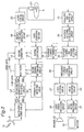
Fig. 2 is an explanatory view of a configuration
of an apparatus for recording and/or reproducing data
to/from the optical disk by using the recording method
described referring to Figs. 1A to 1G (the apparatus
hereinbelow will be referred to as an
"recording/reproducing apparatus"). The
recording/reproducing apparatus includes an antenna 9, a
multichannel tuner circuit 11, a video/audio-source-data
separating circuit 12, a multiplexer 17, a record formatter
16, a system controller 13, a record-encoding modulation
circuit 19, a laser driving circuit 20, and an optical
pickup 21. Each of the aforementioned components function
primarily in a recording operation for data onto the
optical disk 6. In addition, the recording/reproducing
apparatus includes, as a reproduction processing circuit
system, an equalizer and digitizing circuit 22, a playback-decoding-demodulating
circuit 23, a playback-channel
determining circuit 24, a playback-channel-time-division
selection circuit 25, a video/audio-playback-frame
separating circuit 26, an audio decoding circuit 27, an
audio-signal processing circuit 28, a video decoding
circuit 30, and a video-signal processing circuit 31.
Moreover, the recording/reproducing apparatus includes an
operation section 14 on which a user performs various
setting operations.
Hereinbelow, recording operation of the
recording/reproducing apparatus configured as above will be
described.
First, the antenna 9 receives a radio signal 10
including programs of a plurality of channels on a
broadcast such as digital broadcast. From the received
broadcast programs, a user selects programs desired to be
recorded onto the optical disk with the operation section
14. Thereby, a relevant command is issued to the system
controller 13.
The system controller 13 transfers channel
information in the broadcast programs selected by the user
to the multichannel tuner circuit 11. The multichannel
tuner circuit 11 converts in frequency only radio signals
of the channels selected by the user into a base-band
digital signals. The encoded video and audio data
described with reference to Figs. 1A, 1B, and 1C are output
from the multichannel tuner circuit 11.
The video/audio-source-data separating circuit 12
separates video and audio data on the individual channels
which have been output from the multichannel tuner circuit
11, into video data and audio data in each frame. The
separated audio data on the multiple channels is input to
the record formatter 16, and the video data on the multiple
channels is input to the multiplexer 17.
Subsequently, the system controller 13 transfers
information on the channels that is to be recorded in units
of a frame (for example, in the case shown in Fig. 1,
information that the individual channels are uniformly
recorded in every three frames) to a record-channel
determining circuit 15. According to the information
received from the system controller 13, the record-channel
determining circuit 15 outputs a gate signal for only an
interval of frame of the channel determined in units of a
frame. Then, the gate signal is used to control the
multiplexer 17, and only video signals of the channels to
be recorded are selectively output through the multiplexer
17.
Video data selectively output from the
multiplexer 17 is represented by a hatched data block in
Figs. 1A, 1B, and 1C.
The record formatter 16 couples the video data on
the channels selected by the multiplexer 17 to audio data
in the individual frames of all the channels, arranges the
coupled data, and thereby generates and outputs the coupled
data as data arrays that are to be practically recorded on
the track 1 of the optical disk (See Fig. 1D).
As described above, by selecting channels
containing video data desired to be recorded for each frame,
data on an arbitrary multiple number of video channels can
be arranged onto the track 1 of the optical disk 6 as shown
in Fig. 1D without increasing the recording rate of the
optical disk.
Subsequently, the record-encoding modulation
circuit 19 modulates binary data output from the record
formatter 16 into a modulated code that is to be recorded
onto the optical disk 6. The modulated signal is input to
the laser driving circuit 20, and a laser beam source in
the optical pickup 21 is applied with a pulse modulation
according to the modulated signal. Subsequently, the laser
beam is reduced by the optical pickup 21 into fine
spotlight, and recording-required data as shown in Fig. 1D
is recorded onto the track 1 of the optical disk 6.
Hereinbelow, reproduction operation of the
recording/reproducing apparatus will be described.
The equalizer and digitizing circuit 22 converts
a signal reproduced with the optical pickup 21 from the
track 1 of the optical disk 6 into a digital signal. Then,
the playback-decoding-demodulating circuit 23 demodulates
the digital signal into binary data. An output of the
playback-decoding-demodulating circuit 23 is demodulated
and output in the form of a data array as shown in Fig. 1D.
Using the operation section 14, a user selects a
playback-desired channel desired to be reproduced from
video channels recorded on the optical disk 6, and issues a
relative command to the system controller 13.
The system controller 13 transfers information
for specifying channels selected by the user to the
playback-channel determining circuit 24. According to the
specifying information received from the system controller
13, the playback-channel determining circuit 24 determines
a playback channel. In addition, according to the output
received from the playback-decoding-demodulating circuit,
the playback-channel determining circuit 24 identifies the
interval relating to video data and audio data which
includes data on the playback channel, and outputs a gate
signal only for the identified interval. In specific, the
top of the video and audio data in each frame includes a
flag indicating to which channel the data belongs. The
playback-channel determining circuit 24 references the flag
to thereby identify the channel to which read-out frame
data belongs, and outputs a gate signal at the interval of
the playback specified channel. Thereafter, according to
the gate signal from the playback-channel determining
circuit 24, the playback-channel-time-division selection
circuit 25 is controlled to select only a video channel
signal desired to be reproduced and output. Data arrays of
video and audio data of the playback-channel selected and
output as described above are formed as shown in Figs. 1E,
1F, and 1G.
Subsequently, the video and audio data selected
by the playback-channel-time-division selection circuit 25
is separated in the video/audio-playback-frame separating
circuit 26 into audio data and video data. The separated
audio data passes through the audio decoding circuit 27 and
the audio-signal processing circuit 28 to output sound from
a speaker 29. On the other hand, the separated video data
passes through the video decoding circuit 30 and the video-signal
processing circuit 31 to be displayed on a monitor
32.
As described above, with the
recording/reproducing apparatus having the configuration
shown in Fig. 2, recording-designated channels are
determined in units of a frame. Thereby,
recording/reproduction of an arbitrary number of selected
video channels can be implemented even though the recording
data rate of the recording/reproducing apparatus is
constant.
Figs. 3A to 3G are explanatory views regarding an
optical disk recording method and optical disk record
formats according to Embodiment 2.
In the above-described recording method, video
information on three channels is selected, and video data
is uniformly selected and recorded in units of three frames
in each of the channels. However, the intervals of the
frames selected in units of a channel may be changed. This
is effective when only a specific channel is desired to be
recorded/played back to produce a motion picture of high
quality, that is, a motion picture with a smoother motion.
For example, when synchronously recording a movie
program on one channel and music programs of two channels,
it may be desired that the movie program on one channel is
played back with a smoother motion picture than that of the
other two music programs.
Hereinbelow, a description will be made regarding
a method for implementing reproduction for the a-channel
data representing a motion picture that is smoother than
those on other b-channel and c-channel.
Fig. 3A shows a state where video information on
the selected a-channel is encoded to digital-signal blocks
arranged in units of frames. Figs. 3B and 3C each show a
state where video information on each on the other channels
is encoded to data blocks arranged in units of one screen
frame.
As is shown in Fig. 3D, from the three channels,
specific recording-desired channels are determined in units
of a screen frame. Then, video data on the determined
channels are arranged and recorded within a one-frame time
onto the track 1 of the optical disk.
To reproduce the a-channel video data with a
motion picture smoother than those of the b-channel and the
c-channel, as shown in Fig. 3D, the a-channel is recorded
onto the track 1 of the optical disk at every three frames,
and the b-channel and the c-channel are recorded thereto at
every four frames.
More specifically, recording-desired channels are
selected as follows. The a-channel is selected for the
first frame, the b-channel is selected for the second frame,
the a-channel is selected for the third frame, the c-channel
is selected for the fourth frame, the a-channel is
selected for the fifth frame, the b-channel is selected for
the sixth frame, and the a-channel is selected for the
seventh frame.
Subsequently, a description will be made
regarding a reproducing method for video data and audio
data arranged and recorded as shown in Fig. 3D.
As shown in Fig. 3E, to reproduce the a-channel,
Va1 and Aa1 are selected in the first frame, Aa2 is
selected in the second frame, Va3 and Aa3 are selected in
the third frame, Aa4 is selected in the fourth frame, Va5
and Aa5 are selected in the fifth frame, Aa6 is selected in
the sixth frame, and Va7 and Aa7 are selected in the
seventh frame. Then, the individually selected data is
sequentially and intermittently reproduced. By such the
sequential reproduction, video data is reductively or
intermittently reproduced in every two frames, and audio
data can be played back in all frames. Hence, original
sounds can be completely reproduced.
Similarly, as shown in Fig. 3F, to reproduce the
b-channel, Ab1 is selected in the first frame, Vb2 and Ab2
are selected in the second frame, Ab3 is selected in the
third frame, Ab4 is selected in the fourth frame, Ab5 is
selected in the fifth frame, Vb6 and Ab6 are selected in
the sixth frame, and Ab7 is selected in the seventh frame.
Then, the individually selected data is sequentially and
intermittently reproduced. By such the sequential
reproduction, video data of the b-channel is reductively
reproduced in every four frames, and audio data can be
reproduced in all the frames. Hence, original sounds can
be completely reproduced.
Furthermore, as shown in Fig. 3G, to reproduce
the c-channel, Ac1 is selected in the first frame, Ac2 is
selected in the second frame, Ac3 is selected in the third
frame, Vc4 and Ac4 are selected in the fourth frame, Ac5 is
selected in the fifth frame, Ac6 is selected in the sixth
frame, and Ac7 is selected in the seventh frame. Then, the
individually selected data is sequentially and
intermittently reproduced. By such the sequential
reproduction, video data of the c-channel is reductively
reproduced in every four frames, and audio data can be
played back in all the frames. Hence, original sounds can
be completely reproduced.
As described above, the individual channel is
reproduced intermittently with the same intermittent
interval as that at recording, that is, the a-channel is
reproduced in units of two frames, and the other channels
such as the b-channel and the c-channel are reproduced in
units of four channels. This enables the a-channel data to
be presented more smoothly than the b- and c-channel data.
In this way, the arbitrarily change in the frame
interval for recording video data on a specific channel
enables the video data on the specific channel to be
presented more smoothly.
With the configuration shown in Fig. 2, the frame
interval is set to two frames for the a-channel, and the
frame interval is set to four frames for the other b-channel
and c-channel. However, a viewer/listener may
arbitrarily set the frame intervals of the individual
channels depending on the contents of video information.
The recording method as illustrated in Fig. 3 can
be implemented in a configuration similar to the
recording/reproducing apparatus of Embodiment 1 (See Fig.
2). However, a viewer/listener of user inputs information
relating to a channel including video data which the
viewer/listener desires to present more smoothly (such
information is referred to as "priority channel
information" hereinbelow) in the user-operation section 14,
and a command is issued to the system controller 13.
The system controller 13 transfers the priority
channel information to the record-channel determining
circuit 15. According to the information received from the
system controller 13, the record-channel determining
circuit 15 outputs a gate signal in which a frame interval
of the priority channel reduced shorter than a frame
interval of the other channels. Others can be implemented
in the same configuration as that shown in Fig. 11.
With the above-described configuration, the frame
interval for recording the video data can be arbitrarily
changed depending on the contents of video information, and
the frame rate for a specific channel is thereby increased
to enable the video data to be presented more smoothly.
The above-described frame interval is arbitrarily
set by the viewer/listener depending on the contents of
video information. However, in a configuration in which
video data includes attribute information representing the
contents of video data, the attribute information may be
detected to determine the frame interval of each channel.
For example, video data transferred with a
digital broadcast includes attribute data representing the
contents of the broadcast program. The attribute includes,
for example, data representing the type of broadcast
programs (a news program, a music program, a movie program,
and an animation program). The attribute information is
built in video data on individual channels as a data flag.
The apparatus may be programmed such that the attribute
information is detected before the video data is recorded
onto an optical disk, and then, for example, the movie
program and the animation program are recorded at a half of
the frame interval for the news program or the music
program.
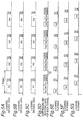
Figs. 4A and 4D show record formats, and are
explanatory views of formats of video data including built-in
attribute data. Attribute data D is arranged in a
latter-half portion of video data Vxy of each channel. Fig.
4A shows attribute data D1 built in a latter-half portion
of video data Vay of the a-channel. Fig. 3B shows
attribute data D2 built in a latter-half portion of video
data Vby of the b-channel. Fig. 4C shows attribute data D2
built in a latter-half portion of video data Vcy of the c-channel.
In the formats, the attribute data "D1"
represents a movie program, and the attribute data "D2"
represents a music program. Fig. 4D shows a state in which
the attribute data D1 and D2 are detected, channels to be
recorded are determined according to the detection result,
and the frame intervals are set. For example, when the
movie program having the attribute "D1" is detected, a 1/2
frame interval in comparison to a frame interval of the
other attributes is set therefor to thereby enable smooth
reproduction of the motion picture.
By using the attribute data as above, a
viewer/listener need not to carry out a complicated
procedure for determining the frame rate for each program.
Only by initially determining the frame-interval
arrangement, the frame interval can be set automatically.
A method of reproducing data in a record track
for which the frame interval is determined using the
attribute data is the same as that shown in Figs. 3E, 3F,
and 3G. Hence, description of the method will be omitted.
When the recording is performed according to the
above-described method, even though the frame rate is not
manually set by the viewer/listener, the movie program can
be automatically reproduced more smoothly than the music
program.
In a case where the attribute data is not
included in video data in a digital broadcast, the feature
of a motion vector included in the video data can be
extracted to presume the attribute thereof.
As above, referring to Figs. 3 and 4, description
has been made regarding the case in which the video
information on three channels is selected. As a matter of
course, however, even in a case where arbitrary N channels
are selected, regardless of the number of selected channels,
recording can be implemented at the optical disk recording
rate being maintained.
The recording method described with reference to
Fig. 4 can be implemented using the recording/reproducing
apparatus having the configuration shown in Fig. 11. In
this case, an attribute-data detecting circuit 34 detects
attribute data included in video data in a digital
broadcast. Specifically, the attribute-data detecting
circuit 34 separates attribute data from video and audio
source data to detect the attribute, and inputs the
attribute data to the record-channel determining circuit 15.
According to information received from the
attribute-data detecting circuit 34, the record-channel
determining circuit 15 outputs a gate signal representing
data of a narrowed frame interval for a channel of which
data needs to be reproduced more smoothly. For example, a
short frame interval is set for a channel which is detected
as a movie program, while a long frame interval is set for
a channel which is detected as a music program.
Figs. 5A to 5G are explanatory views showing an
optical disk recording method and a data arrangement on an
optical disk according to the present embodiment. These
figures show a method of selecting video information on
three-channel broadcast programs from broadcasted programs
and recording the video information at a predetermined
recording rate, and a method of reproducing the recorded
information; and the figures shows record formats of the
video information.
Fig. 5A shows a state where video information on
a selected a-channel is encoded to digital-signal blocks
arranged in units of frames. Figs. 5B and 5C show states
where video information on respective b- and c-channels
selected is encoded to digital-signal blocks arranged in
units of frames.
Fig. 5D shows that, in order to record video data
and audio data for three channels, video data and audio
data for each channel are compressed in units of frame and
arranged in one-frame time, so that the compressed data for
three channels can be included within one-frame time on the
track 1 of the optical disk.
For example, each of the video data Va1 to Va4 of
the a-channel is compressed so as to be of 1/3 in data
amount. Similarly, each of the video data Vb1 to Vb4 of
the b-channel is compressed so as to be of 1/3 in data
amount, and each of the video data Vc1 to Vc4 of the c-channel
is compressed so as to be of 1/3 in data amount.
Thus, the amounts of data are time-division multiplexed to
be recordable within a one-frame time and thereby recorded
into the track 1 of the optical disk.
In this way, the video data on each channel is
compressed in data amount so as to be of 1/3 of the amount
of encoded data. That is, the video data is compressed to
be of 1/(number of channels) in data amount. Thereby,
three-channel video data can be arranged in each frame.
More specifically, when the data amount of the
video data per unit frame time that can be recorded onto
the optical disk is M, the amount of selected-channel video
data recorded within the unit frame time is substantially
M/N.
In this way, by compressing the amount of video
data in units of frames at a rate of 1/(number of channels),
the video data can be recorded substantially at a constant
recording rate, regardless of the number of the selected
video channels.
The compression ratio for each channel is not
limited to 1/(number of channels). The compression ratio
can be set for each channel so that a total amount of N
channels of compressed video data to be recorded in a
record time T which is the minimum of time or period in
which at least one video frame of each channel is included
is less than or equal to a data amount that can be recorded
in the time T at the maximum recording rate of the optical
disk.
However, regarding the audio data synchronizing
with the video data in units of frames in each channel, the
audio data of all channels are recorded into each frame
regardless of, for example, the number of selected video
channels and the compression ratio of the video data. The
reason for the above is that the audio data has less data
amount in a frame than the amount of the video data and
therefore the audio data on all the channels can easily be
arranged in one frame.
In Figs. 5A to 5G, audio data synchronizing with
the video data Va1 of the a-channel is Aa1, audio data
synchronizing with the video data Vb1 of the b-channel is
Ab1, and audio data synchronizing with the video data Vc1
of the c-channel is Ac1.
The audio data that is synchronous with the video
data is arranged and recorded as shown in Fig. 5D.
Specifically, the audio data is not compressed in any
frames, and is recorded as in the data amount when decoded.
In Fig. 5D, gaps 18 which are unrecorded portions
are arranged between the record-data frames. However, the
data may be recorded continually without the gaps 18
provided.
In addition, one record frame may be recorded
over different sector fields 7 of the optical disk 6 (See
Fig. 12).
Next, a description will be made regarding a
method of reproducing video and audio data those arranged
and recorded onto the track 1 of the optical disk in a
manner as shown in Fig. 5D.
As shown in Fig. 5E, when reproducing the a-channel,
Va1 and Aa1 in the first frame, Va2 and Aa2 in the
second frame, Va3 and Aa3 in the third frame, and Va4 and
Aa4 in the fourth frame are selected respectively and
reproduced sequentially and intermittently. After such the
sequential reproduction, the video data is decompressed
and then decoded. Since the audio data is not compressed
at recording, it can be decoded without decompression.
As shown in Fig. 5F, when reproducing the b-channel,
Vb1 and Ab1 in the first frame, Vb2 and Ab2 in the
second frame, Vb3 and Ab3 in the third frame, and Vb4 and
Ab4 in the fourth frame are selected respectively and
reproduced sequentially and intermittently.
Similarly, as shown in Fig. 5G, when reproducing
the c-channel, Vc1 and Ac1 in the first frame, Vc2 and Ac2
in the second frame, Vc3 and Ac3 in the third frame, and
Vc4 and Ac4 in the fourth frame are selected respectively
and reproduced sequentially and intermittently.
In this way, by compressing the amount of video
data in units of frames at a rate of 1/(number of channels),
the video data can be recorded substantially at a constant
recording rate, regardless of the number of the selected
video channels.
With a small number of channels selected for data
recording, the compression ratio for the video data on each
channel becomes relatively small. Hence, higher-quality
image can be reproduced. Consequently, regardless of the
number of the selected channels, the recording rate of the
optical disk device can be efficiently used.
In the above, the case where video information on
three channels has been selected has been described.
However, even when arbitrary N channels are selected, the
embodiment can be carried out similar to the above.
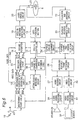
Fig. 6 shows a configuration of a
recording/reproducing apparatus designed to
record/reproduce the optical disk 6 by employing the
recording method described referring to Fig. 5.
First, recording operation will be described
referring to a configuration shown in Fig. 12.
The recording/reproducing apparatus receives a
radio signal 10 relating to a plurality of programs of
broadcast such as digital broadcast through an antenna 9.
A viewer/listener selects a broadcast program desired to be
recorded onto the optical disk from the received broadcast
programs by using an operation section 14 and commands a
system controller 13.
The system controller 13 transfers channel
information in the broadcast program selected by the user
to a multichannel tuner circuit 11. The multichannel tuner
circuit 11 converts in frequency only a radio signal of the
channel selected by the user to a base-band digital signal.
The encoded video and audio data on the individual a-, b-,
and c-channels in Figs. 5A, 5B, and 5C represent data
arrays that have been output from the multichannel tuner
circuit 11.
The video/audio-source-data separating circuit 12
separates video and audio data on the individual channels
which have been output from the multichannel tuner circuit
11 into video data and audio data respectively in units of
frames. The separated audio data on the multiple channels
is input to the record formatter 16, and the video data is
input to a video-data-amount compressing circuit 35.
Subsequently, the system controller 13 transfers
information relating to data compression for each selected
channel to a record-channel-compression-ratio determining
circuit 36. In the cases shown in Figs. 5A to 5H, the data
compression information is information for setting a
uniform compression ratio for all channels. According to
the information received from the system controller 13, the
record-channel-compression-ratio determining circuit 36
determines data compression ratios α for each channels so
that when recording is performed at a predetermined
recording rate of the recording/reproducing apparatus, the
total data amounts of video data on the individual selected
channels can be recorded within a one-frame time.
The data compression ratios α thus determined are
input to the video-data-amount compressing circuit 35, and
video data is compressed so as to enable the total data
amounts of the individual channels to be recorded within a
one-frame time. Specifically, the video data is compressed
so that data having data amount of (total data amount of
compressed video data)/(recording rate of the optical disk)
is recordable within a one-frame time. For example, when
"N" represents the number of selected channels, the
compression ratio α is obtained as expressed by α=(1/N).
Subsequently, as shown in Fig. 5D, a record
formatter 16 couples the individual-channel video data
compressed by the video-data-amount compressing circuit 35
and uncompressed all-channel audio data, and arranges the
coupled data. Thereby, the record formatter 16 generates
and outputs the coupled data as data arrays that are to be
practically recorded onto the track 1 of the optical disk 6.
As described above, the data compression ratio
for each selected channel is controlled such that the
amount of data to be recorded at a predetermined recording
rate specific to the optical disk can be recorded within a
one-frame time. This allows data on an arbitrary number of
video channels to be arranged onto the track 1 of the
optical disk 6 as shown in Fig. 5D without increasing the
recording rate of the optical disk.
Subsequently, a record-encoding modulation
circuit 19 modulates binary data output from the record
formatter 16 into a modulated code to be recorded onto the
optical disk 6. The modulated signal is input to a laser
driving circuit 20, and a laser optical source in an
optical pickup 21 is modulated in pulse according to the
modulated signal. Subsequently, the laser beam is reduced
in the optical pickup 21 into fine spot light, and data to
be recorded as shown in Fig. 5D is recorded onto the track
1 of the optical disk 6.
Hereinbelow, reproducing operation (playback
operation) will be described with reference to Fig 6.
An equalizer and digitizing circuit 22 converts a
signal reproduced with the optical pickup 21 from the track
1 of the optical disk 6 into a digital signal. Then, a
playback-decoding-demodulating circuit 23 demodulates the
digital signal into binary data. An output of the
playback-decoding-demodulating circuit 23 is demodulated in
the form of a data array as shown in Fig. 5D.
Using an operation section 14, a user selects a
channel which the user want to reproduce from video
channels recorded on the optical disk 6, and commands the
system controller 13.
The system controller 13 transfers the video-channel
information selectively specified by the user to a
playback-channel determining circuit 24. According to the
information received from the system controller 13, the
playback-channel determining circuit 24 outputs a gate
signal only for an interval of video and audio data on the
determined playback channel. At this time, according to an
output signal of the playback-decoding-demodulating circuit
and predetermined information included at the top of a read
out frame, the playback-channel determining circuit 24 is
capable of determining whether the frame is to be played
back. Then, the playback-channel-time-division selection
circuit 25 is controlled according to the gate signal, and
only a video channel signal which is desired to be
reproduced is selected and output by the selection circuit
25.
Data arrays of video and audio data selected and
output as described above are formed as shown in Figs. 5E,
5F, and 5G.
Subsequently, the video and audio data selected
by the playback-channel-time-division selection circuit 25
is separated by a video/audio-playback-frame separating
circuit 26 into audio data and video data. The audio data
separated and output is decoded by an audio decoding
circuit 27. The decoded data is converted into an audio
signal through an audio-signal processing circuit 28 and
the audio signal is output from a speaker 29. On the other
hand, the video data is decoded, and the decoded data is
reproduced by a video decoding circuit 30 on a monitor 32
through a video-signal processing circuit 31. At this time,
the video data is decoded by the video decoding circuit 30
after decompressed according to the compression-ratio
information included in the video data. However, the audio
data is not decompressed since it has not been compressed.
Fig. 7 is an explanatory view showing an optical
disk recording method and optical disk record formats
according to the present embodiment.
In the Embodiment 4, video information on three
channels is selected, and the video data for each channel
is compressed at the same compression rate, for recording.
However, the data compression ratio may be changed
depending on the channel when the video data for one
channel is desired to be recorded or reproduced with a
higher quality than other channels.
For example, when one channel with a movie
program and two channels of music programs are selected and
synchronously recorded, it is preferable that the movie
program on one channel is reproduced with a higher quality
than music programs on other two channels.
Assuming the case as above, Figs. 7A to 7G show
that the a-channel is reproduced with a higher quality than
b- and c-channels.
Fig. 7A shows a state where video information on
the selected a-channel is encoded to digital-signal blocks
arranged in units of frames. Figs. 7B and 7C each shows a
state where video information on each of the other channels
is encoded to data blocks arranged in units of screen
frames.
Fig. 7D shows a state where video data on each
channel is compressed in units of frames, and video data
and audio data on three channels are arranged to be
included within a one-frame time onto the track 1 of the
optical disk.
In the example shown in Fig. 7D, in order to
reproduce the video data of the a-channel with a higher
quality than other channels, video data is recorded on
track 1 of the optical disk by making the compression ratio
for the video data on the a-channel lower than ratios for
the video data on the other channels. For example, the
data compression ratios are set so that the record data
amount of the a-channel is twice the record data amount of
the b- channel or the c-channel.
By changing the compression ratio depending on
the channel as in the above-described example, video data
of only the specific channel can be recorded on the optical
disk with high quality.
Hereinbelow, a description will be given
regarding a reproducing method for the video data and the
audio data arranged and recorded onto the track 1 of the
optical disk, as shown in Fig. 7D.
As shown in Fig. 7E, to reproduce the a-channel,
Va1 and Aa1 in the first frame, Va2 and Aa2 in the second
frame, Va3 and Aa3 in the third frame, and Va4 and Aa4 in
the fourth frame are selected respectively and reproduced
sequentially and intermittently. Then, the video data is
decompressed and decoded. The audio data can be decoded
without decompression since the audio data is not
compressed at the recording step.
As in the playback for the a-channel, regarding
reproduction of the b-channel, video data and audio data on
only the b-channel are selected in units of frames and
sequentially and intermittently reproduced (See Fig. 7F).
However, the data amount of the b-channel is half of the
data amount of the a-channel, and therefore the decoded
played-back image quality of the b-channel is lower than
that of the a-channel.
As in the playback for the b-channel, regarding
reproduction of the c-channel, video data and audio data on
only the c-channel are selected in units of frames and
sequentially and intermittently reproduced (See Fig. 7G).
However, the data amount of the c-channel is half of the
data amount of the a-channel, and therefore the decoded
played-back image quality of the c-channel is lower than
that of the a-channel.
As described above, since the a-channel has the
data amount twice as much as the data amount of the other
b- or c-channel, the a-channel can be reproduced with a
higher video quality.
In this way, by arbitrarily changing the record
data amount depending on the contents of video information
on only a specific video channel, the specific channel can
be reproduced with a higher video quality.
While the data amount of the a-channel is set
twice as much as that of other channels in the example
shown in Figs. 7A to 7G, a viewer/listener may set an
arbitrary record data amount or compression ratio for each
video channel depending on the contents of the video
information.
The recording method described referring to Figs.
7A to 7G can be implemented with a recording/reproducing
apparatus having the configuration shown in Fig. 6. In
this case, a viewer/listener uses a user operation section
37 to input information (priority channel information)
relating to a video channel for which higher quality
reproduction is desired and to command the system
controller 13.
The system controller 13 transfers the priority
channel information to the record-channel-compression-ratio
determining circuit 36. According to the information
received from the system controller 13, the record-channel-compression-ratio
determining circuit 36 controls the
video-data-amount compressing circuit 35 so that the
compression ratio of video data on the priority channel is
determined with priority to the other channels to produce
the priority channel with a higher video quality. Other
operations are similar to those already described above.
In the configuration as described above, the
compression ratio of video data can be arbitrarily changed
depending on the contents of video data, and a specific
channel can be reproduced with a higher video quality.
Figs. 8A and 8D are explanatory views showing an
optical disk recording method and formats of an optical
disk according to the present embodiment. In this case,
attribute data is included in a latter-half portion of
video data Vxy of each channel. Fig. 8A shows attribute
data D1 built in a latter-half portion of video data Vay of
the a-channel. Fig. 8B shows attribute data D2 built in a
latter-half portion of video data Vby of the b-channel.
Fig. 8C shows attribute data D2 built in a latter-half
portion of video data Vcy of the c-channel.
In Figs. 8A to 8D, the attribute data "D1"
represents a movie program, and the attribute data "D2"
represents a music program. The attribute data is detected,
and record data amount or compression ratio for each
channel are set automatically (See Fig. 8D). For example,
when a movie program having the attribute "D1" is detected
according to the attribute data, the record data amount of
the a-channel is set twice as much as that of the other
attribute, resulting in reproduction of a smoother motion
picture.
By using the attribute data as above, a
viewer/listener need not to carry out a complicated
procedure for allocation of the data amount to each program.
Once the allocation of the record data amount depending on
the contents of video information is initially determined,
the frame interval can be set automatically thereafter.
A method of reproducing data on a record track
for which the frame interval is determined based on the
attribute data is the same as that shown in Figs. 7E, 7F,
and 7G. Hence, description of the method will be omitted.
According to the above described method, even
when the record data amount is not manually set by the
viewer/listener, it is possible to record or reproduce
automatically a movie program more smoothly than a music
program.
In a case where the attribute data is not
included in video data in a digital broadcast, the
attribute can be presumed by extracting a feature of a
motion vector included in the video data.
As above, referring to Figs. 7A to 7G and 8A to
8D, description has been made regarding the case in which
the video information on three channels is selected. As a
matter of course, however, even in a case where arbitrary N
channels are selected, regardless of the number of selected
channels, recording can be implemented at the constant
recording rate of the optical disk.
The recording method described with reference to
Figs. 8A to 8D can be implemented using a
recording/reproducing apparatus having the configuration
shown in Fig. 6. In this case, however, the attribute-data
detecting circuit 34 detects attribute data included in a
digital broadcast. Specifically, the attribute-data
detecting circuit 34 separates and detects attribute data
from video and audio source data to input the attribute
data to the record-channel-compression-ratio determining
circuit 36.
The record-channel-compression-ratio determining
circuit 36 determines the priority in the compression ratio
for each channel according to information received from the
attribute-data detecting circuit 34. For example, a low
data compression ratio is determined for a channel detected
as a movie program, while a high data compression ratio is
determined for a channel detected as a music program.
Other configuration is similar to that shown in Fig. 12.
According to the configuration described above,
the viewer/listener need not intentionally determine the
video quality, the movie program can be automatically
reproduced with a higher quality than the music program.
An optical disk recording apparatus of the
present embodiment records data by determining amount of
data to be recorded for each channel in units of frames
such that the total amount of data to be recorded until
broadcast programs in selected plurality of channels end is
less than or equal to a remaining data capacity (data
capacity of free area ) of the optical disk in which data
can be recorded.
Referring to Figs. 9A to 9H, operation of the
optical disk recording/reproducing apparatus of the present
embodiment will be described. The figures show the case
that three channels, namely, a-, b- and c-channels are
selected as channels to be recorded, and that programs
broadcasted on each channel in a predetermined time band is
recorded (same as Embodiment 8). In addition, the
recording/reproducing apparatus of the present embodiment
has the configuration shown in Fig. 6.
Fig. 9A shows a state where video information on
a selected a-channel is encoded to digital-signal blocks
arranged in units of frames. Figs. 9B and 9C show states
where video information on respective b- and c-channels
selected is encoded to digital-signal blocks arranged in
units of frames.
In the recording/reproducing apparatus, before
recording the video information, the system controller 13
detects a free area (remaining capacity) of the optical
disk onto which data is to be stored. The remaining
capacity can be known from a track address. In addition,
the system controller 13 computes the total amounts of the
encoded video data and audio data on three channels (See
Figs. 9A, 9B, and 9C) in a period up to the ends of the
broadcast programs (from start of recording to end of
recording). The record-channel-compression-ratio
determining circuit 36 sets, according to the data amounts,
a data compression ratio β for recording the video data on
each channel to cause the total data amounts of the three
channels to be less than or equal to the remaining capacity
of the optical disk. For example, the data compression
ratio β is obtained as follows;
β = (1/N)·(Dr/R)/Tf
where "N" represents the number of channels, "Tf"
represents the time from start of the broadcast program to
end of the broadcast program, "Dr" represents the remaining
data capacity of the optical disk, and "R" represents the
recording rate of the optical disk recording/reproducing
apparatus. Since the audio-data amount is substantially
and sufficiently smaller than the video-data amount, even
when audio data of N channels is recorded, the compression
ratio β can be obtained using the above expression.
The system controller 13 compares a period
required from the start of broadcast-program to the end of
broadcast-program (the time hereinbelow will be referred to
as a "data record time") and a time for which data can be
recorded onto the optical disk (the time hereinbelow will
be referred to as a "recordable time"). The recordable
time of the optical disk is obtained by (remaining data
capacity of the optical disk)/(recording rate of the
optical disk).
If the data record time is less than or equal to
the recordable time of the optical disk, according to the
method described in Embodiment 4, the encoded data on the
three channels is compressed at a compression ratio α, and
then recorded within the one-frame time.
If the data record time is longer than the
recordable time of the optical disk, the data is compressed
in units of frames at the compression ratio β, and is then
recorded. However, if video data and audio data that have
been compressed in units of frames at the compression ratio
β are recorded continuously in real time at the recording
rate of the optical disk, all the data for a period up to
the end of broadcast-program cannot be recorded. For this
reason, in the above case, intermittent recording is
performed as shown in Fig. 9D.
As shown in Fig. 9D, a record data time length 2
for one frame when compression is performed so that a total
amount of data to be recorded is less than or equal to the
remaining data capacity of the optical disk becomes shorter
than a time length of one frame when recording operation is
performed continuously in real time. Therefore, as shown
in Fig. 9D, it needs intermittent recording with gaps 3 for
temporarily halting the record operation to perform
physically efficient recording for the data onto a
recording area of the optical disk at a predetermined
recording rate of the recording/reproducing apparatus.
Fig. 9E shows a record-data array on the real
track 1 in a state after the intermittent recording has
thus been performed. The time length for recording one
frame data is shorter than one frame of time length on real
time at a predetermined recording rate of the
recording/reproducing apparatus. When excluding gaps 6
between record areas, the data is recorded without gaps on
the track 1 of the optical disk and thereby a high
recording efficiency in physical format is achieved.
When continuous reproduction is performed at a
predetermined reproduction rate of the
recording/reproducing apparatus, the reproduction is
performed with data timing as shown in Fig. 9E.
The total amount of video data Va1 to Van and
audio data Aa1 to Aan for a period up to the broadcast-program
end time is maintained less than or equal to a
remaining data capacity 5 of the optical disk.
In this way, the data compression ratio is
determined by the following such that the total amount of
data to be recorded is less than or equal to the remaining
data capacity of the optical disk. Then, the data is
recorded intermittently using the data compression ratio
thus determined. Thus, regardless of the remaining data
capacity of the optical disk, it can complete to record
programs of selected arbitrary video channels in a period
up to the end of the broadcast program at a predetermined
recording rate of the recording/reproducing apparatus.
A description will be made regarding a
reproducing method for video data and audio data that are
arranged and recorded onto the track 1 of the optical disk,
as shown in Fig. 9E.
As shown in Fig. 9F, to reproduce the a-channel,
Va1 and Aa1 are first reproduced. Before the subsequent
Va2 and Aa2 are played back, period 4 serving to
temporarily halt the reproduction operation is provided.
Similarly, the period 4 is provided between (Va2 and AA2)
and (Va3 and Aa3).
In order to reproduce data thus intermittently
recorded onto the track (See Fig. 9E), the data is
intermittently reproduced similar to the case of recording.
Thereby, the compressed recorded data can be reproduced in
real time in units of video/audio frames.
Similarly, regarding the b-channel and the c-channel,
period 4 serving to temporarily halt the
reproduction operation is provided, and intermittent
reproduction is performed, as shown in Figs. 9G and 9H.
Thereby, the compressed recorded data can be reproduced in
real time in units of video/audio frames.
As described above, even at a fixed reproduction
rate of the recording/reproducing apparatus, the
intermittent reproduction is performed to reproduce the
track onto which the data is intermittently recorded by
setting the data compression ratio to cause the total
amount of data to be recorded to be less than or equal to
the remaining data capacity of the optical disk. According
to this arrangement, broadcast programs of the data-recorded
channels can securely be recorded in a period up
to the end of the broadcast program.
As a matter of course, the intervals for
temporarily halting the recording operation and the
reproducing operation, i.e., the intervals in the
intermittent recording and the intermittent reproduction
need not be set in units of frames of video/audio data.
The intervals may be arbitrarily set depending on the
capacity of data buffer memory of the recording/reproducing
apparatus.
Moreover, the data compression ratios for the
individual channels need not be identical. The data
compression ratios may be arbitrarily set according to the
methods shown in Figs. 7 and 8 as long as the total amount
of data to be recorded in a period up to the end of the
broadcast program is less than or equal to the remaining
data capacity of the optical disk.
Referring to Fig. 9, description has been made
with reference to the example in which either the start
time or the end time of the broadcast programs of the
channels is the same. In addition, the number of the
audio-data frames thereof is also the same in the example.
However, the start time and the end time need not be
identical for the individual broadcast programs, and may be
arbitrarily set.
In this embodiment, in case that broadcast
programs of a plurality of channels are multiplexed and
recorded by thinning out frames according to the method
disclosed in Embodiment 1, the optical disk remaining data
capacity is also considered to cause the recording to be
completed regardless of the optical disk remaining data
capacity.
More specifically, in the present embodiment, a
total amount of data on selected plurality of channels for
a period from the start of recording to the end of
recording is compared with an optical disk remaining data
capacity in which further data can be recorded. Then, the
number of frames of video data on the individual channels
is regulated so that a total amount of data on selected
plurality of channels for a period from the start of
recording to the end of recording is less than or equal to
the optical disk remaining data capacity.
Figs. 10A to 10G are explanatory views showing an
optical disk recording method and optical disk record
formats according to the present embodiment. The optical
disk recording/reproducing apparatus of the present
embodiment has the configuration shown in Fig. 2.
Fig. 10A shows a state where video information on
a selected a-channel is encoded to digital-signal blocks
arranged in units of frames. Similarly, Figs. 10B and 10C
show states where video information on respective b- and c-channels
selected is encoded to digital-signal blocks
arranged in units of one screen frame.
The recording/reproducing apparatus of the
present embodiment determines the number of frames to be
recorded in a recording operation so that the total amount
of data relating to video and audio data on the channels to
be recorded for a period up to the end of program is less
than or equal to a detected optical disk remaining data
capacity.
For that purpose, in the recording/reproducing
apparatus, before recording the video information, the
system controller 13 computes a total amount of the encoded
video data and audio data on three channels (Figs. 10A, 10B,
and 10C) in a period up to the end of program.
Concurrently, the system controller 13 detects the
remaining data capacity of the optical disk to be recorded.
Then, the system controller 13 compares a time up to the
end of recording with a remaining recordable time of the
optical disk.
When the time up to the end of program is shorter
than or equal to the optical disk remaining time, the
encoded data in one frame of the selected channel is
continually recorded at a recording rate of the
recording/reproducing apparatus within the one-frame time
according to the method described in Embodiment 1.
When the time up to the end of program is longer
than the optical disk remaining time, the total number of
recordable frames in the optical disk becomes smaller than
the number of the encoded frames shown in Figs. 10A, 10B,
and 10C. Accordingly, it needs to thin out and record the
encoded frames so that the total number of data frames to
be recorded is smaller than or equal to the total number of
recordable frames.
Fig. 10D shows an example case where the video
data in the a-channel is thinned out and recorded on every
six frames, that is, Va4, Va10, Va16, ... are thinned out (or
reduced). In this case, the audio data is not reduced. In
the example shown in Fig. 10D, the a-channel is recorded at
every six frames, and the data in each of the b-channel and
the c-channel is recorded at every three frames.
When continuous reproduction is simply attempted
in real time at a recording rate of the
recording/reproducing apparatus for video data and audio
data that have been compressed in units of frames, all data
in a period up to the end of program can not be recorded.
Concretely, the total number of frames of video-data that
can be recorded in a period up to the end of the program
becomes smaller than the number of the encoded frames shown
in Figs. 10A, 10B, and 10C. Accordingly, as shown in Fig.
10D, it needs intermittent recording with periods 3 for
temporarily halting the recording operation to record the
data within the remaining recording area of the optical
disk without changing the recording rate of the
recording/reproducing apparatus.
Fig. 10E shows a record data array on the real
track 1 in a state after the intermittent recording has
thus been performed. In this case, regarding the portions
corresponding to reduced video frames (Va4, Va10, ...),
excluding gaps 6 between recording areas, the data is
recorded on the track 1 of the optical disk frames without
gaps, thereby resulting in a high physical format
efficiency.
When data is reproduced continuously at a
predetermined reproduction rate of the
recording/reproducing apparatus, the reproduction is
performed with data timing as shown in Fig. 10E.
In the case shown in the figure, the total amount
of video data and audio data to which the channel
determination and the frame reduction in the individual
frames in a period up to the end of the program are applied
is maintained less than or equal to a remaining data
capacity 5 of the optical disk.
In this way, an arrangement is made such that
intermittent recording is performed by setting the numbers
of frames of the individual channels so as to cause the
total amount of record data to be less than or equal to the
remaining data capacity of the optical disk. According to
this arrangement, broadcast programs of the video channels
to be recorded can securely be recorded in a period up to
the end of the broadcast programs, regardless of a fixed
recording rate of the recording/reproducing apparatus or a
remaining data capacity of the optical disk.
Hereinbelow, a description will be made regarding
a reproduction method for video data and audio data that
are arranged and recorded onto the track 1 of the optical
disk, as shown in Fig. 10E.
As shown in Fig. 10F, in order to reproduce the
a-channel, Va1, Aa1, Aa2, and Aa3 are reproduced
sequentially. Before Aa4 is reproduced, period 4 serving
to temporarily halt the reproduction operation is provided.
When reproducing data thus intermittently recorded onto the
track (Fig. 10E), areas relating to reduced frames are
intermittently reproduced as in the case of recording.
Thereby, video and audio can be reproduced on real time.
Similarly to the a-channel, regarding the b-channel
and the c-channel, intermittent reproduction is
performed, where period 4 serving to temporarily halt the
reproduction operation is individually provided, as shown
in Figs. 10G and 10H. Thereby, the compressed record data
can be reproduced on real time in units of frames relating
to video/audio data.
As described above, even at a fixed reproducing
rate, intermittent reproduction is performed to reproduce
the track for which intermittent recording has been
performed by determining the numbers of frames of the
individual channels so that the total amount of record data
is less than or equal to the remaining data capacity of the
optical disk.
It is noted that the interval for temporarily
halting the record operation and the reproduction operation,
i.e., the interval of the intermittent recording or the
intermittent reproduction, may be arbitrarily set depending
on the capacity of data buffer memory of the
recording/reproducing apparatus.
The video data on the a-channel is thinned out in
the example shown Figs. 10A to 10H. However, video data on
arbitrary channels may be thinned out depending on the
smoothness of a reproduced motion picture, as far as a
total amount of data required to be recorded in a period up
to the end of the broadcast-program is less than or equal
to the remaining data capacity of the optical disk.
Alternatively, data may be thinned out uniformly for
individual channels. For example, when a time of a
broadcast program to be recorded is 100 minutes and the
optical disk remaining data capacity has a space for
recording data for 40 minutes, the time differential is 60
minutes. In this case, the number of frames may be reduced
to result in 20-minute reduction in each channel.
Furthermore, referring to Fig. 9, description has
been made with reference to the example in which either the
start time or the end time of the broadcast program of each
channel is the same, and the number of the audio-data
frames thereof is also the same. However, it is clear that
the start time, the end time and the number of frames need
not be identical for the individual broadcast programs, and
they may be arbitrarily set.
The present invention has been described with
reference to the specific embodiments. However, many other
modifications, corrections and applications will be
apparent to those skilled in the art. The present
invention should not therefore be limited to the specific
embodiments disclosed herein, and it could be limited only
by the scope of the appended claims.
Claims (38)
- A method of recording video data on N (N is an integer) channels synchronously onto an optical disk, the video data formed of a time series of video frames, comprising:determining a compression ratio for each channel so that a total data amount for the N channels of video data after compression that is recorded during a record time T is less than or equal to a data amount that can be recorded at a maximum recording rate of the optical disk during the record time T, the record time T being a minimum time of record times individually comprising at least one video frame for each channel;compressing the video data in units of frames in each channel at the determined compression ratio; andrecording the compressed data onto the optical disk,
whereby the video data is recorded onto the optical disk so that a total amount of data on the N channels to be recorded in a unit time is substantially constant regardless of the number of channels to be recorded. - The method according to claim 1, wherein the compression ratio for the video data on each channel is set to 1/N.
- The method according to claim 1, further comprising determining an allocation ratio of the data amount to be recorded for each channel in the record time T to all data to be recorded in the record time T according to contents of the video data on each channel,
wherein the compression ratio for each channel is determined according to the determined allocation ratio. - The method according to claim 3, wherein, when the video data to be recorded includes attribute data indicating the contents of the video data, the attribute data is detected from the video data, and the contents of the video data on each channel is determined according to the detected attribute data.
- The method according to claim 1, wherein, when the video data on each channel is accompanied by audio data synchronizing therewith,
the determining determines the compression ratio for the video data on each channel so that a total data amount for N channels of video and audio data after compression that is recorded during the record time T is substantially constant regardless of the input number of channels, and
the method comprises arranging the video compressed at the determined compression ratio and audio data into each frame in a predetermined order, to thereby record the data onto the optical disk. - The method according to claim 1, wherein, when the individual video data on the N channels (N is an integer) in the predetermined record time is to be synchronously recorded onto the optical disk,
the method further comprises computing a total data amount of video data on the N channels to be recorded in the predetermined record time, and a capacity of free area of the optical disk in which data can be recorded,
whereby the compression ratio is determined so that the total amount of data to be recorded is less than or equal to the capacity of free area of the optical disk in which data can be recorded. - A method of recording video data of N (N is an integer) channels synchronously onto an optical disk, the video data formed of a time series of video frames, comprising:selecting one of the N'channels in units of video frames, as a channel of which video data is recorded; andrecording the video data in the video frame on the selected channel onto the optical disk,
whereby N channels of the video data are time-division multiplexed in units of video frames and recorded onto the optical disk. - The method according to claim 7, wherein each channel is selected at every N frames as a channel of which video data is recorded.
- The method according to claim 7, wherein an allocation ratio of the number of frames for each channel to be recorded in a predetermined time is determined according to the contents of the video data on each channel.
- The method according to claim 9, wherein, when the input video data comprises attribute data indicating the contents of the video data, the method comprises detecting the attribute data from the video data, and determining the contents of the video data on each channel according to the detected attribute data.
- The method according to claim 7, wherein, when the input video data on each channel is accompanied by audio data synchronizing therewith, the audio data on N channels accompanying the video data on the one channel is recorded in units of video frames.
- The method according to claim 7, wherein, when each of the video data on the N channels (N is an integer) in a predetermined record time is to be synchronously recorded onto the optical disk, the method comprises:computing a total data amount for the N channels of video data to be recorded in the predetermined record time, and a capacity of free area of the optical disk in which data can be recorded;comparing the total data amount to be recorded with the capacity of free area of the optical disk; anddetermining, when the total data amount to be recorded is greater than the capacity amount of the optical disk, the number of the video frames to be recorded in a predetermined time so that in at least one of the N channels the total data amount to be recorded is less than or equal to the capacity of free are of the optical disk.
- A method of reproducing recorded data from an optical disk onto which N channels (N is an integer) of video data are compressed at a predetermined compression ratio and arranged in a predetermined channel order to thereby be recorded, comprising:inputting information for designating a channel to be reproduced;reading data from the optical disk in units of frames;reproducing video data on the designated channel to be reproduced from the video data recorded in the read frame, after the video data is decompressed; andreproducing audio data that is included in the read frame and is on the channel to be recorded.
- A method of reproducing recorded data from an optical disk having an area in which video data on N channels (N is an integer) is recorded in units of frames by a time-division multiplexing method,
the optical disk storing the video data selected in every predetermined number of frames on one channel, and audio data on all channels continuous to the video data,
the method comprising:inputting information for designating a channel to be reproduced;reading data from the optical disk in units of frames; andif video data included in the read frame is video data of designated channel to be reproduced, then reproducing the video data, and further reproducing audio data that is included in the read frame and is on the designated channel to be recorded. - An optical disk having an area in which video data on N channels (N is an integer) are recorded in units of frames by a time-division multiplexing method, the disk comprising,
a frame area which is provided corresponding to a video frame series in one channel and in which video data on each channel is multiplexed and recorded in units of video frames,
the frame area having a data length equal to a total for N channels of data length in one frame of video data which is compressed at a predetermined compression ratio; and
wherein the predetermined compression ratio is determined so that a total data amount for the N channels of video data to be recorded during a record time T is less than or equal to a data amount that can be recorded during the record time T at a maximum recording rate of the optical disk, the record time T being a minimum time in record times individually including at least one video frame for each channel. - The optical disk according to claim 15, wherein the predetermined compression ratio is set to 1/N.
- The optical disk according to claim 15, wherein an allocation ratio of the data amount in the frame area for each channel is determined according to the contents of the video data.
- The optical disk according to claim 17, wherein, when the video data includes attribute data indicating the contents of the video data, the attribute data is detected from the video data, and the contents of the video data on each channel are determined according to the detected attribute data.
- The optical disk according to claim 15, wherein, when the input video data on each channel is accompanied by audio data synchronizing therewith, the audio data on the N channels accompanying the video data on the one channel is recorded in units of video frames.
- An optical disk having an area in which video data of N (N is an integer) channels are recorded synchronously onto an optical disk, the video data formed of a time series of video frames, wherein
one of the N channels is selected as a channel of which video data is to be recorded, in units of video frames, and
an area for recording the video data in the video frame on the selected channel onto the optical disk is arranged on a track of the optical disk. - The optical disk according to claim 20, wherein a video frame arranged at a (mN+C)th position on the track is arranged on the track of the optical disk as a recording area for a c-th channel of the N channels, where "m" is an integer that is 0 or larger, and "C" is an integer that is "1" or larger and is "N" or smaller.
- The optical disk according to claim 20, wherein the one channel is selected according to the contents of the video data.
- The optical disk according to claim 22, wherein, when the video data includes attribute data indicating the contents of the video data, the attribute data is detected from the video data, and the contents of the video data on each channel are determined according to the detected attribute data.
- The optical disk according to claim 20, wherein, when the input video data on each channel is accompanied by audio data synchronizing therewith, the audio data on the N channels accompanying the video data on the one channel is recorded in units of video frames.
- An apparatus for recording video data on N (N is an integer) channels synchronously onto an optical disk, the video data formed of a time series of video frames, comprising:a section that determines a compression ratio for each channel so that a total data amount for the N channels of video data after compression that is recorded during a record time T is less than or equal to a data amount that can be recorded at a maximum recording rate of the optical disk during the record time T, the record time T being a minimum time of record times individually comprising at least one video frame for each channel;a section that compresses the video data in units of frames in each channel at the determined compression ratio; anda section that records the compressed data onto the optical disk,
whereby the video data is recorded onto the optical disk so that a total amount of data on the N channels to be recorded in a unit time is substantially constant regardless of the number of channels to be recorded. - The apparatus according to claim 25, wherein the compression ratio for the video data on each channel is set to 1/N.
- The apparatus according to claim 25, further comprising a section that determines an allocation ratio of the data amount to be recorded for each channel in a predetermined time to all data to be recorded in the predetermined time according to contents of the video data on each channel,
whereby the compression ratio for each channel is determined according to the determined allocation ratio. - The apparatus according to claim 26, wherein, when the video data to be recorded includes attribute data indicating the contents of the video data, the attribute data is detected from the video data, and the contents of the video data on each channel is determined according to the detected attribute data.
- The apparatus according to claim 25, wherein, when the video data on each channel is accompanied by audio data synchronizing therewith,
the section for determining determines the compression ratio for the video data on each channel so that a total data amount for N channels of video and audio data after compression that is recorded during the record time T is substantially constant regardless of the input number of channels, and
the apparatus comprises a section that arranges the video and audio data compressed at the determined compression ratio into each frame in a predetermined order, to thereby record the data onto the optical disk. - The apparatus according to claim 25, wherein, when the individual video data on the N channels (N is an integer) in the predetermined record time is to be synchronously recorded onto the optical disk,
the apparatus further comprises a section that computes a total data amount of video data on the N channels to be recorded in the predetermined record time, and a capacity of free area of the optical disk in which data can be recorded,
whereby the compression ratio is determined so that the total amount of data to be recorded is less than or equal to the capacity of free area of the optical disk in which data can be recorded. - An apparatus for recording video data of N (N is an integer) channels synchronously onto an optical disk, the video data formed of a time series of video frames, comprising:a section that selects one of the N channels in units of video frames, as a channel of which video data is recorded; anda section that records the video data in the video frame on the selected channel onto the optical disk,
whereby N channels of the video data are time-division multiplexed in units of video frames and recorded onto the optical disk. - The apparatus according to claim 31, wherein each channel is selected at every N frames as a channel of which video data is recorded.
- The apparatus according to claim 31, wherein an allocation ratio of the number of frames for each channel to be recorded in a predetermined time is determined according to the contents of the video data on each channel.
- The apparatus according to claim 33, wherein, when the input video data comprises attribute data indicating the contents of the video data, the attribute data is detected from the video data, and the contents of the video data on each channel is determined according to the detected attribute data.
- The apparatus according to claim 31, wherein, when the input video data on each channel is accompanied by audio data synchronizing therewith, the audio data on N channels accompanying the video data on the one channel is recorded in units of video frames.
- The apparatus according to claim 31, wherein, in order to record synchronously each of the video data on the N channels (N is an integer) in a predetermined record time onto the optical disk, the apparatus comprises:a section that computes a total data amount for the N channels of video data to be recorded in the predetermined record time, and a capacity of free area of the optical disk in which data can be recorded;a section that compares the total data amount to be recorded with the capacity of free area of the optical disk; anda section that determines, when the total data amount to be recorded is greater than the capacity amount of the optical disk, the number of the video frames to be recorded in a predetermined time so that in at least one of the N channels the total data amount to be recorded is less than or equal to the capacity of free are of the optical disk.
- An apparatus for reproducing recorded data from an optical disk onto which N channels (N is an integer) of video data are compressed at a predetermined compression ratio and arranged in a predetermined channel order to thereby be recorded, comprising:a section that inputs information for designating a channel to be reproduced;a section that reads data from the optical disk in units of frames; anda section that reproduces video data on the designated channel to be reproduced from the video data recorded in the read frame, after the video data is decompressed, and audio data that is included in the read frame and is on the channel to be recorded.
- An apparatus for reproducing recorded data from an optical disk having an area in which video data on N channels (N is an integer) is recorded in units of frames by a time-division multiplexing method,
the optical disk storing the video data selected in every predetermined number of frames on one channel, and audio data on all channels continuous to the video data,
the apparatus comprising:a section that inputs information for designating a channel to be reproduced;a section that reads data from the optical disk in units of frames; anda section that, if video data included in the read frame is video data of designated channel to be reproduced, then reproduces the video data, and audio data that is included in the read frame and is on the designated channel to be recorded.
Applications Claiming Priority (3)
| Application Number | Priority Date | Filing Date | Title |
|---|---|---|---|
| JP20305699 | 1999-07-16 | ||
| JP20305699 | 1999-07-16 | ||
| PCT/JP2000/004746 WO2001006780A1 (en) | 1999-07-16 | 2000-07-14 | Optical disk, optical disk recording/reproducing apparatus, and recording/reproducing method |
Publications (2)
| Publication Number | Publication Date |
|---|---|
| EP1206137A1 true EP1206137A1 (en) | 2002-05-15 |
| EP1206137A4 EP1206137A4 (en) | 2006-01-04 |
Family
ID=16467618
Family Applications (1)
| Application Number | Title | Priority Date | Filing Date |
|---|---|---|---|
| EP00946337A Withdrawn EP1206137A4 (en) | 1999-07-16 | 2000-07-14 | OPTICAL DISK, OPTICAL DISC RECORDING / REPRODUCING APPARATUS, AND RECORDING / REPRODUCING METHOD |
Country Status (4)
| Country | Link |
|---|---|
| EP (1) | EP1206137A4 (en) |
| CN (1) | CN1204743C (en) |
| AU (1) | AU6017100A (en) |
| WO (1) | WO2001006780A1 (en) |
Families Citing this family (1)
| Publication number | Priority date | Publication date | Assignee | Title |
|---|---|---|---|---|
| CN101185341B (en) * | 2005-05-30 | 2010-07-14 | 松下电器产业株式会社 | Recording and reproducing device and integrated circuit |
Family Cites Families (12)
| Publication number | Priority date | Publication date | Assignee | Title |
|---|---|---|---|---|
| JP3122191B2 (en) * | 1991-10-16 | 2001-01-09 | 株式会社東芝 | Recording and playback device |
| KR940004478B1 (en) * | 1991-11-26 | 1994-05-25 | 주식회사 금성사 | Video cassette recorder |
| JPH05328293A (en) * | 1992-05-20 | 1993-12-10 | Hitachi Ltd | Image compression recorder with plural recording channels |
| JPH066774A (en) * | 1992-06-23 | 1994-01-14 | Olympus Optical Co Ltd | Television broadcasting method by time axis compression signal |
| US5625504A (en) * | 1992-09-10 | 1997-04-29 | Hitachi, Ltd. | Magnetic recording and reproducing system |
| JPH08172645A (en) * | 1994-12-17 | 1996-07-02 | Sanyo Electric Co Ltd | Stereoscopic information recording medium and stereoscopic information recorder |
| EP0762756B1 (en) * | 1995-09-11 | 2002-03-06 | Matsushita Electric Industrial Co., Ltd. | Video signal recording and reproducing apparatus |
| JPH09116870A (en) * | 1995-10-21 | 1997-05-02 | Sony Corp | Playback device |
| CN1866378B (en) * | 1996-02-28 | 2010-09-29 | 松下电器产业株式会社 | disc playback device |
| JP3567607B2 (en) * | 1996-05-16 | 2004-09-22 | ソニー株式会社 | Simultaneous recording and playback device |
| JP2985842B2 (en) * | 1997-08-25 | 1999-12-06 | 株式会社日立製作所 | Digital information recording / reproducing device |
| JPH11134795A (en) * | 1997-10-29 | 1999-05-21 | Sanyo Electric Co Ltd | Plural channel recording method, magneto-optical disk drive and magneto-optical disk |
-
2000
- 2000-07-14 CN CN00810308.9A patent/CN1204743C/en not_active Expired - Fee Related
- 2000-07-14 WO PCT/JP2000/004746 patent/WO2001006780A1/en not_active Ceased
- 2000-07-14 EP EP00946337A patent/EP1206137A4/en not_active Withdrawn
- 2000-07-14 AU AU60171/00A patent/AU6017100A/en not_active Abandoned
Also Published As
| Publication number | Publication date |
|---|---|
| CN1204743C (en) | 2005-06-01 |
| WO2001006780A1 (en) | 2001-01-25 |
| AU6017100A (en) | 2001-02-05 |
| CN1360792A (en) | 2002-07-24 |
| EP1206137A4 (en) | 2006-01-04 |
Similar Documents
| Publication | Publication Date | Title |
|---|---|---|
| US6266478B1 (en) | Information record medium, apparatus for recording the same and apparatus for reproducing the same | |
| EP1235221B1 (en) | Information record medium | |
| CN100409352C (en) | Information recording apparatus and information reproducing apparatus | |
| US6778761B1 (en) | Information record medium, apparatus for recording the same and apparatus for reproducing the same | |
| US7929828B1 (en) | Method for editing source video to slow motion or fast motion on the recordable media | |
| US6658196B2 (en) | Editing technique merging video signals recorded on the same optical disk | |
| US20010043784A1 (en) | Picture quality adjustment method and picture quality adjustment apparatus | |
| JP2003514419A (en) | MPEG bitstream decoding and image editing without re-encoding for rewritable DVDs | |
| JP4658277B2 (en) | Method and apparatus for recording and playback of transmitted program works | |
| JPH11259976A (en) | Optical disk drive | |
| US6768864B1 (en) | Recording and reproducing apparatus compressing reproduced information | |
| EP1206137A1 (en) | Optical disk, optical disk recording/reproducing apparatus, and recording/reproducing method | |
| US5809203A (en) | Selected screen reproducing method for video compact disc reproducing system and apparatus thereof | |
| US6453113B1 (en) | Editing apparatus and editing method | |
| US6744971B1 (en) | Information signal recording/reproducing apparatus and method thereof | |
| JP3518337B2 (en) | Data recording method and apparatus | |
| JP3665390B2 (en) | Playback device, optical disc, and recording device | |
| JP4223151B2 (en) | Audio additional recording method and optical disk recording / reproducing apparatus | |
| JP2001251580A (en) | Dvd video scenario reproducing device | |
| EP1331816B1 (en) | Method for editing source video to fast motion on the recordable media | |
| JPWO2001006780A1 (en) | Optical disc, optical disc recording/playback device, and recording/playback method | |
| JPH11134795A (en) | Plural channel recording method, magneto-optical disk drive and magneto-optical disk | |
| JP4611187B2 (en) | Video recording device | |
| KR100275873B1 (en) | Multi-optical disc player and control method | |
| JP3281741B2 (en) | Disc player |
Legal Events
| Date | Code | Title | Description |
|---|---|---|---|
| PUAI | Public reference made under article 153(3) epc to a published international application that has entered the european phase |
Free format text: ORIGINAL CODE: 0009012 |
|
| 17P | Request for examination filed |
Effective date: 20020218 |
|
| AK | Designated contracting states |
Kind code of ref document: A1 Designated state(s): AT BE CH CY DE DK ES FI FR GB GR IE IT LI LU MC NL PT SE |
|
| AX | Request for extension of the european patent |
Free format text: AL;LT;LV;MK;RO;SI |
|
| RBV | Designated contracting states (corrected) |
Designated state(s): DE FR GB |
|
| A4 | Supplementary search report drawn up and despatched |
Effective date: 20051116 |
|
| STAA | Information on the status of an ep patent application or granted ep patent |
Free format text: STATUS: THE APPLICATION HAS BEEN WITHDRAWN |
|
| 18W | Application withdrawn |
Effective date: 20070507 |