EP1206068A2 - Method of increasing data rate via clacl switching in a wireless data communication network - Google Patents
Method of increasing data rate via clacl switching in a wireless data communication network Download PDFInfo
- Publication number
- EP1206068A2 EP1206068A2 EP01000603A EP01000603A EP1206068A2 EP 1206068 A2 EP1206068 A2 EP 1206068A2 EP 01000603 A EP01000603 A EP 01000603A EP 01000603 A EP01000603 A EP 01000603A EP 1206068 A2 EP1206068 A2 EP 1206068A2
- Authority
- EP
- European Patent Office
- Prior art keywords
- clock rate
- sequence
- transmitting
- fixed sequence
- encoded data
- Prior art date
- Legal status (The legal status is an assumption and is not a legal conclusion. Google has not performed a legal analysis and makes no representation as to the accuracy of the status listed.)
- Granted
Links
Images


Classifications
-
- H—ELECTRICITY
- H04—ELECTRIC COMMUNICATION TECHNIQUE
- H04L—TRANSMISSION OF DIGITAL INFORMATION, e.g. TELEGRAPHIC COMMUNICATION
- H04L7/00—Arrangements for synchronising receiver with transmitter
- H04L7/04—Speed or phase control by synchronisation signals
- H04L7/06—Speed or phase control by synchronisation signals the synchronisation signals differing from the information signals in amplitude, polarity or frequency or length
-
- H—ELECTRICITY
- H04—ELECTRIC COMMUNICATION TECHNIQUE
- H04J—MULTIPLEX COMMUNICATION
- H04J3/00—Time-division multiplex systems
- H04J3/22—Time-division multiplex systems in which the sources have different rates or codes
-
- H—ELECTRICITY
- H04—ELECTRIC COMMUNICATION TECHNIQUE
- H04L—TRANSMISSION OF DIGITAL INFORMATION, e.g. TELEGRAPHIC COMMUNICATION
- H04L1/00—Arrangements for detecting or preventing errors in the information received
- H04L1/0078—Avoidance of errors by organising the transmitted data in a format specifically designed to deal with errors, e.g. location
- H04L1/0083—Formatting with frames or packets; Protocol or part of protocol for error control
Definitions
- This invention relates generally to wireless communications, and more particularly to a method of increasing the data rate in a wireless data communication network (e.g., Ethernet) via clock switching.
- a wireless data communication network e.g., Ethernet
- the present invention is directed to a method of increasing the data rate in a wireless data communication network such as Ethernet via clock switching.
- the method employs clock switching between the preamble and the encoded data portion of a packet structure.
- a shift block includes a tail sequence and a head sequence that is inserted between the preamble and the encoded data portion.
- the clock switching occurs within the shift block between the tail and the head sequences.
- the tail sequence and the head sequence are each constrained to be a fixed sequence.
- An embodiment of the present invention is directed to a method of increasing the data rate in a wireless data communication network wherein the method comprises the steps of: constraining an end portion of a preamble associated with a data packet to be a first fixed sequence; constraining a beginning portion of encoded data associated with the data packet to be a second fixed sequence; transmitting the data packet preamble at a first clock rate; changing the first clock rate to a second clock rate between the first fixed sequence and the second fixed sequence; and transmitting the encoded data at the second clock rate.
- a method of increasing the rate of data transmission in a wireless communication network comprises the steps of: transmitting at a first clock rate, a data packet preamble associated with a data packet and having an end portion comprising a first fixed sequence; and transmitting at a second clock rate, encoded data associated with the data packet and having a beginning portion comprising a second fixed sequence.
- the existing IEEE 802.11b standard, and the TI proposed 22 Mbps extension to the standard, are based upon an 11 Msps symbol rate and a bandwidth occupancy of 20 MHz.
- This parameter which expresses the amount of "waveform spreading" can be modeled with a (complex) baseband transmission signal of the form where the complex samples ⁇ C k ⁇ represent the encoded data and the real valued pulse shape p ( t ) determines the spectrum of the signal.
- the samples ⁇ C k ⁇ are drawn from the QPSK signal set while the 22 Mbps samples belong to the 8-PSK signal set.
- This second pulse 12 increases the symbol rate by 50% when compared to the first pulse 10; yet it maintains the same 20 MHz bandwidth.
- Figure 2B is an eye diagram illustrating a 20 MHz signal with an 11 Msps symbol rate
- Figure 2A is an eye diagram illustrating a 20 MHz signal with a 16.5 MHz symbol rate.
- a method to improve the throughput of transmission while maintaining interoperability with existing networks is achieved with a changing of the symbol clock after the packet preamble.
- This method of improving the date rate allows for the reuse of modulation and encoding methods of the IEEE standard and TI extension discussed herein before.
- the three PBCC® modes that operate at 5.5 Mbps, 11 Mbps and 22 Mbps without clock switching, transmit at the rate of 8.25 Mbps, 16.5 Mbps and 33 Mbps when the clock is switched from the 11 Mbps used in the header to 16.5 Mbps during the data portion of the packet.
- two baseband signals are generated such as: and where x 1 ( t ) represents the initial transmission (e.g., the preamble) and x 2 ( t ) represents the subsequent transmission.
- Figures 3A and 3B are diagrams illustrating waveform effects due to clock switching from 11 Msps to 16.5 Msps using a fixed 20 MHz bandwidth.
- Figure 3B shows the composite x ( t ) signal while
- Figure 3A shows the two component signals x 1 ( t ) and x 2 ( t - ⁇ ).
- Each signal consists of random data.
- the inter-symbol interference that occurs due to the change in the clock rate can be easily seen in Figure 3B. This distortion effects both the end of the first signal as well as the beginning of the second signal.
- one embodiment of the present inventive method constrains the end of the first signal (the "Tail”) to be a fixed sequence and further constrains the beginning of the second signal (the "Head”) to be a fixed sequence.
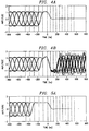
- This technique is demonstrated in Figures 4A and 4B that are diagrams illustrating waveform effects due to clock switching from 11 Msps to 16.5 Msps using a guard band having a head length 2 and a tail length 3.
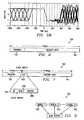
- Figures 5A and 5B are more diagrams illustrating waveform effects due to clock switching from 11 Msps to 16.5 Msps, but instead, using a guard band having a head length 4 and a tail length 6.
- the head is chosen to be a constant (+1) sequence and the tail is chosen to be a constant 180° rotation of the head (-1). This selection has the desirable property that a single well defined transition occurs at the clock change boundary.
- Figure 6 is a diagram illustrating a packet structure 100 without clock switching.
- the packet structure 100 can be seen to have a preamble 102 and an encoded data portion 104.
- the preamble 102 uses a common format that is detectable by all users on the associated network (enumerated as 300 in Figure 8), while the encoded data portion need only be decodable by the intended receiver (302, 304, 306).
- FIG. 7 is a diagram illustrating a clock switch packet structure 200 with clock switching according to one embodiment of the present invention.
- the clock switch packet structure 200 is obtained via insertion of a "shift" block 202 between the preamble 102 and the encoded data 104.
- the clock rate switch occurs within the shift block 202 between the tail sequence 204 and the head sequence 206.
- a ReSync sequence 208 is employed to aid the receiver (302, 304, 306) in re-calibrating tracking loops and other dynamic receiver elements such as adaptive filters and the like.
Landscapes
- Engineering & Computer Science (AREA)
- Computer Networks & Wireless Communication (AREA)
- Signal Processing (AREA)
- Multimedia (AREA)
- Mobile Radio Communication Systems (AREA)
- Small-Scale Networks (AREA)
- Communication Control (AREA)
- Digital Transmission Methods That Use Modulated Carrier Waves (AREA)
Abstract
Description



Claims (9)
- A method of increasing the rate of data transmission in a wireless communication network method comprising:transmitting at a first clock rate, a data packet preamble associated with a data packet and having an end portion comprising a first fixed sequence; andtransmitting at a second clock rate, encoded data associated with the data packet and having a beginning portion comprising a second fixed sequence.
- The method according to claim 1 further comprising:changing the first clock rate to the second clock rate between the end portion and the beginning portion.
- The method according to claim 2, wherein changing the first clock rate to the second clock rate comprises changing the first clock rate to a faster clock rate.
- The method according to claim 2 or claim 3, wherein changing the first clock rate to the second clock rate comprises changing the first clock rate from 11 MHz to 16.5 MHz.
- The method according to any preceding claim further comprising:constraining an end portion of the preamble associated with the data packet to be the first fixed sequence;constraining the beginning portion of encoded data associated with the data packet to be the second fixed sequence;changing the first clock rate to a second clock rate between the first fixed sequence and the second fixed sequence; andtransmitting the encoded data at the second clock rate.
- The method according to any of claims 1 to 5, wherein transmitting at a first clock rate, a data packet preamble associated with a data packet and having an end portion comprising a first fixed sequence, comprises transmitting an end portion constrained to be a constant plus one sequence.
- The method according to claim 6, wherein transmitting at the second clock rate, encoded data associated with the data packet and having a beginning portion comprising a second fixed sequence, comprises transmitting a beginning portion constrained to be a constant 180° rotation of the constant plus one sequence.
- The method according to any of claims 1 to 7, wherein transmitting at the second clock rate, encoded data associated with the data packet and having a beginning portion comprising a second fixed sequence, comprises transmitting a beginning portion constrained to be a constant 180° rotation of the first fixed sequence.
- The method according to any of claims 1 to 8 further comprising:transmitting a resynchronization sequence immediately following transmission of the beginning portion of the encoded data and before transmission of the remaining portion of the encoded data.
Applications Claiming Priority (4)
| Application Number | Priority Date | Filing Date | Title |
|---|---|---|---|
| US24666500P | 2000-11-08 | 2000-11-08 | |
| US30871501P | 2001-07-30 | 2001-07-30 | |
| US246665 | 2001-07-30 | ||
| US308715 | 2001-07-30 |
Publications (3)
| Publication Number | Publication Date |
|---|---|
| EP1206068A2 true EP1206068A2 (en) | 2002-05-15 |
| EP1206068A3 EP1206068A3 (en) | 2003-12-10 |
| EP1206068B1 EP1206068B1 (en) | 2005-11-02 |
Family
ID=26938135
Family Applications (1)
| Application Number | Title | Priority Date | Filing Date |
|---|---|---|---|
| EP20010000603 Expired - Lifetime EP1206068B1 (en) | 2000-11-08 | 2001-11-08 | Method of increasing data rate via clock switching in a wireless data communication network |
Country Status (3)
| Country | Link |
|---|---|
| EP (1) | EP1206068B1 (en) |
| JP (1) | JP3829085B2 (en) |
| DE (1) | DE60114543T2 (en) |
Cited By (4)
| Publication number | Priority date | Publication date | Assignee | Title |
|---|---|---|---|---|
| WO2006063769A1 (en) * | 2004-12-13 | 2006-06-22 | Fraunhofer-Gesellschaft zur Förderung der angewandten Forschung e.V. | Synchronisation device and device for generation of a synchronisation signal |
| US7529534B2 (en) | 2004-12-13 | 2009-05-05 | Fraunhofer-Gesellschaft Zur Foerderung Der Angewandten Forschung E.V. | Signal converter for converting a start signal to an end signal and method for converting a start signal to an end signal |
| US7602856B2 (en) | 2004-12-13 | 2009-10-13 | Fraunhofer-Gesellschaft Zur Foerderung Der Angewandten Forschung E.V. | Mixer for mixing a signal and method for mixing a signal |
| US7627063B2 (en) | 2004-12-13 | 2009-12-01 | Fraunhofer-Gesellschaft Zur Foerderung Der Angewandten Forschung E.V. | Device and method for determining a time of arrival of a receive sequence |
Family Cites Families (3)
| Publication number | Priority date | Publication date | Assignee | Title |
|---|---|---|---|---|
| US5748676A (en) * | 1995-05-01 | 1998-05-05 | Norand Corporation | Network utilizing modified preambles that support antenna diversity |
| US6373899B1 (en) * | 1997-06-30 | 2002-04-16 | Spacenet, Inc. | Combined preamble detection and information method for burst-type digital communication system |
| US6603801B1 (en) * | 1998-01-16 | 2003-08-05 | Intersil Americas Inc. | Spread spectrum transceiver for use in wireless local area network and having multipath mitigation |
-
2001
- 2001-11-07 JP JP2001342149A patent/JP3829085B2/en not_active Expired - Fee Related
- 2001-11-08 EP EP20010000603 patent/EP1206068B1/en not_active Expired - Lifetime
- 2001-11-08 DE DE2001614543 patent/DE60114543T2/en not_active Expired - Lifetime
Cited By (9)
| Publication number | Priority date | Publication date | Assignee | Title |
|---|---|---|---|---|
| WO2006063769A1 (en) * | 2004-12-13 | 2006-06-22 | Fraunhofer-Gesellschaft zur Förderung der angewandten Forschung e.V. | Synchronisation device and device for generation of a synchronisation signal |
| US7525483B2 (en) | 2004-12-13 | 2009-04-28 | Fraunhofer-Gesellschaft Zur Foerderung Der Angewandten Forschung E.V. | Receive device and method for receiving a receive sequence |
| US7529534B2 (en) | 2004-12-13 | 2009-05-05 | Fraunhofer-Gesellschaft Zur Foerderung Der Angewandten Forschung E.V. | Signal converter for converting a start signal to an end signal and method for converting a start signal to an end signal |
| US7602856B2 (en) | 2004-12-13 | 2009-10-13 | Fraunhofer-Gesellschaft Zur Foerderung Der Angewandten Forschung E.V. | Mixer for mixing a signal and method for mixing a signal |
| US7627063B2 (en) | 2004-12-13 | 2009-12-01 | Fraunhofer-Gesellschaft Zur Foerderung Der Angewandten Forschung E.V. | Device and method for determining a time of arrival of a receive sequence |
| US7653166B2 (en) | 2004-12-13 | 2010-01-26 | Fraunhofer-Gesellschaft Zur Foerderung Der Angewandten Forschung E.V. | Synchronization device and device for generating a synchronization signal |
| AU2005315887B2 (en) * | 2004-12-13 | 2010-07-08 | Fraunhofer-Gesellschaft Zur Foerderung Der Angewandten Forschung E.V. | Synchronisation device and device for generation of a synchronisation signal |
| AU2005315887C1 (en) * | 2004-12-13 | 2010-11-25 | Fraunhofer-Gesellschaft Zur Foerderung Der Angewandten Forschung E.V. | Synchronisation device and device for generation of a synchronisation signal |
| CN101116280B (en) * | 2004-12-13 | 2012-08-29 | 弗劳恩霍夫应用研究促进协会 | Synchronisation device and synchronisation method |
Also Published As
| Publication number | Publication date |
|---|---|
| EP1206068A3 (en) | 2003-12-10 |
| DE60114543D1 (en) | 2005-12-08 |
| JP3829085B2 (en) | 2006-10-04 |
| DE60114543T2 (en) | 2006-06-08 |
| EP1206068B1 (en) | 2005-11-02 |
| JP2002208988A (en) | 2002-07-26 |
Similar Documents
| Publication | Publication Date | Title |
|---|---|---|
| US20020172187A1 (en) | Method for data packet acquisition using split preamble | |
| JP2004538717A (en) | Channel Estimation in Multicarrier Transmit Diversity System | |
| KR19990036422A (en) | Burst Mode Preamble | |
| WO1994027388A1 (en) | High speed modem, method and system for achieving synchronous data compression | |
| US7068649B2 (en) | Extended bandwidth homePNA system compatible with homePNA 2.0 | |
| US20020150077A1 (en) | Data transmission method | |
| US9077410B2 (en) | Apparatus and method of transmitting data in multi-carrier system | |
| WO2002091659A3 (en) | Reordering data packets in a communication system | |
| IL185607A (en) | System and method for communicating data using constant amplitude equalized waveform | |
| EP2130306A1 (en) | Method and device for reducing transmission power of packet oriented data and communication system comprising such device | |
| EP1206068B1 (en) | Method of increasing data rate via clock switching in a wireless data communication network | |
| CN101326752A (en) | System, apparatus and method for single carrier block transmission with adaptive guard interval | |
| US7184412B2 (en) | Method of increasing data rate in a wireless data communication network via clock switching | |
| FR2820564A1 (en) | TRANSMITTING AND RECEIVING DEVICES OF MODULE SIGNAL | |
| EP1362449B1 (en) | Data transmission method with a level of error protection selected from among several pre-defined levels | |
| US20030128749A1 (en) | Method and device for the automatic selection of the bit rate in high frequency transmissions | |
| CN210274106U (en) | Medium converter, transmitter and receiver for such a medium converter | |
| Baier et al. | Performance of M-algorithm MLSE equalizers in frequency-selective fading mobile radio channels | |
| Dettmar et al. | Modulation for HIPERLAN type 2 | |
| AU718488B2 (en) | Method of digital demodulation | |
| US6111920A (en) | Method and system for timing recovery in a baud-rate sampled data stream | |
| Nafie et al. | Enhancements to the Bluetooth specification | |
| Nafie et al. | Decision feedback equalization for Bluetooth systems | |
| KR100436207B1 (en) | Homerf system using channel estimation and dc offset compensation | |
| EP1798917A1 (en) | Method of passing a constant bit rate digital signal through an ethernet interface and system for carrying out the method |
Legal Events
| Date | Code | Title | Description |
|---|---|---|---|
| PUAI | Public reference made under article 153(3) epc to a published international application that has entered the european phase |
Free format text: ORIGINAL CODE: 0009012 |
|
| AK | Designated contracting states |
Kind code of ref document: A2 Designated state(s): AT BE CH CY DE DK ES FI FR GB GR IE IT LI LU MC NL PT SE TR |
|
| AX | Request for extension of the european patent |
Free format text: AL;LT;LV;MK;RO;SI |
|
| PUAL | Search report despatched |
Free format text: ORIGINAL CODE: 0009013 |
|
| AK | Designated contracting states |
Kind code of ref document: A3 Designated state(s): AT BE CH CY DE DK ES FI FR GB GR IE IT LI LU MC NL PT SE TR |
|
| AX | Request for extension of the european patent |
Extension state: AL LT LV MK RO SI |
|
| 17P | Request for examination filed |
Effective date: 20040611 |
|
| AKX | Designation fees paid |
Designated state(s): AT BE CH CY DE DK ES FI FR GB GR IE IT LI LU MC NL PT SE TR |
|
| RTI1 | Title (correction) |
Free format text: METHOD OF INCREASING DATA RATE VIA CLOCK SWITCHING IN A WIRELESS DATA COMMUNICATION NETWORK |
|
| GRAP | Despatch of communication of intention to grant a patent |
Free format text: ORIGINAL CODE: EPIDOSNIGR1 |
|
| RBV | Designated contracting states (corrected) |
Designated state(s): DE FR GB |
|
| GRAS | Grant fee paid |
Free format text: ORIGINAL CODE: EPIDOSNIGR3 |
|
| GRAA | (expected) grant |
Free format text: ORIGINAL CODE: 0009210 |
|
| AK | Designated contracting states |
Kind code of ref document: B1 Designated state(s): DE FR GB |
|
| REG | Reference to a national code |
Ref country code: GB Ref legal event code: FG4D |
|
| REF | Corresponds to: |
Ref document number: 60114543 Country of ref document: DE Date of ref document: 20051208 Kind code of ref document: P |
|
| ET | Fr: translation filed | ||
| PLBE | No opposition filed within time limit |
Free format text: ORIGINAL CODE: 0009261 |
|
| STAA | Information on the status of an ep patent application or granted ep patent |
Free format text: STATUS: NO OPPOSITION FILED WITHIN TIME LIMIT |
|
| 26N | No opposition filed |
Effective date: 20060803 |
|
| REG | Reference to a national code |
Ref country code: FR Ref legal event code: PLFP Year of fee payment: 15 |
|
| REG | Reference to a national code |
Ref country code: FR Ref legal event code: PLFP Year of fee payment: 16 |
|
| PGFP | Annual fee paid to national office [announced via postgrant information from national office to epo] |
Ref country code: DE Payment date: 20161130 Year of fee payment: 16 Ref country code: GB Payment date: 20161026 Year of fee payment: 16 Ref country code: FR Payment date: 20161017 Year of fee payment: 16 |
|
| REG | Reference to a national code |
Ref country code: DE Ref legal event code: R119 Ref document number: 60114543 Country of ref document: DE |
|
| GBPC | Gb: european patent ceased through non-payment of renewal fee |
Effective date: 20171108 |
|
| REG | Reference to a national code |
Ref country code: FR Ref legal event code: ST Effective date: 20180731 |
|
| PG25 | Lapsed in a contracting state [announced via postgrant information from national office to epo] |
Ref country code: DE Free format text: LAPSE BECAUSE OF NON-PAYMENT OF DUE FEES Effective date: 20180602 Ref country code: FR Free format text: LAPSE BECAUSE OF NON-PAYMENT OF DUE FEES Effective date: 20171130 |
|
| PG25 | Lapsed in a contracting state [announced via postgrant information from national office to epo] |
Ref country code: GB Free format text: LAPSE BECAUSE OF NON-PAYMENT OF DUE FEES Effective date: 20171108 |