EP1205963A1 - Hochdruckentladungslampe und Bogenröhre - Google Patents
Hochdruckentladungslampe und Bogenröhre Download PDFInfo
- Publication number
- EP1205963A1 EP1205963A1 EP01309378A EP01309378A EP1205963A1 EP 1205963 A1 EP1205963 A1 EP 1205963A1 EP 01309378 A EP01309378 A EP 01309378A EP 01309378 A EP01309378 A EP 01309378A EP 1205963 A1 EP1205963 A1 EP 1205963A1
- Authority
- EP
- European Patent Office
- Prior art keywords
- conductive member
- capillary tube
- tube part
- discharge lamp
- pressure discharge
- Prior art date
- Legal status (The legal status is an assumption and is not a legal conclusion. Google has not performed a legal analysis and makes no representation as to the accuracy of the status listed.)
- Granted
Links
Images


Classifications
-
- H—ELECTRICITY
- H01—ELECTRIC ELEMENTS
- H01J—ELECTRIC DISCHARGE TUBES OR DISCHARGE LAMPS
- H01J61/00—Gas-discharge or vapour-discharge lamps
- H01J61/02—Details
- H01J61/36—Seals between parts of vessels; Seals for leading-in conductors; Leading-in conductors
- H01J61/366—Seals for leading-in conductors
-
- H—ELECTRICITY
- H01—ELECTRIC ELEMENTS
- H01J—ELECTRIC DISCHARGE TUBES OR DISCHARGE LAMPS
- H01J61/00—Gas-discharge or vapour-discharge lamps
- H01J61/02—Details
- H01J61/36—Seals between parts of vessels; Seals for leading-in conductors; Leading-in conductors
-
- H—ELECTRICITY
- H01—ELECTRIC ELEMENTS
- H01J—ELECTRIC DISCHARGE TUBES OR DISCHARGE LAMPS
- H01J61/00—Gas-discharge or vapour-discharge lamps
- H01J61/02—Details
- H01J61/36—Seals between parts of vessels; Seals for leading-in conductors; Leading-in conductors
- H01J61/361—Seals between parts of vessel
- H01J61/363—End-disc seals or plug seals
Definitions
- the present invention relates to a high-pressure discharge lamp and an arc tube built in the high-pressure discharge lamp.
- This metal halide lamp includes an arc tube having a main tube part and a pair of capillary tube parts.
- the main tube part has a pair of electrodes arranged opposite to each other in an internal discharge space.
- the pair of capillary tube parts is disposed at both ends of the main tube part and continues into the discharge space.
- a rod-like feeder for providing a current the corresponding electrode carries from outside.
- the feeder is sealed to the capillary tube part with a seal member such as frit glass.
- the feeder consists of two different types of metal which are connected into a rod. That is to say, a metal with high halogen resistance, such as tungsten, is used in one part of the feeder extending from the inner electrode to the middle of a capillary tube part, and niobium, whose thermal expansion coefficient is closer to that of the seal member, is used for the other part of the feeder extending from the middle to outside. Only the niobium portion of the feeder is sealed with the seal member.
- a metal with high halogen resistance such as tungsten
- having such a sealing structure prevents corrosion of the part of the feeder which is exposed to halides the discharge space, since that part of the feeder is made of tungsten which is highly resistant to halides. Also, no crack will be produced due to thermal stress, since the feeder is sealed with the seal member at the niobium portion and niobium has a thermal expansion coefficient approximate to those of the seal member and the capillary tube part. This extends the lamp life substantially.
- Another metal halide lamp is devised that uses as a feeder only a conductive cermet, which is a sintered mixture of tungsten and alumina, instead of using two types of metals of different properties as described above.
- this material is of low mechanical strength, and a portion of the conductive cermet that is protruding from a capillary tube part is easily broken by external impact and vibration.
- High-pressure discharge lamps other than metal halide lamps also contain some kinds of halides to extend a lamp life by using halogen cycle. Therefore, the above problem can occur in these high-pressure discharge lamps, too.
- a portion of the first conductive member of at least one of the feeders that is located inside the capillary tube part is halogen-resistant, which reduces the possibility of the feeder being corroded by halides that have penetrated in the seal member during the lighting. This prevents an enclosed substance from being leaked to outside.
- the feeder has a second conductive member located outside. the capillary tube part, which is different from the first conductive member.
- the fixing member which is the seal member.
- the sealing member used to seal the capillary tube part can also be used to fix the second conductive member to the capillary tube part, thus streamlining the manufacturing processing.
- the high-pressure discharge lamp is provided with the fixing member so as to completely cover a connecting portion where the first conductive member is connected with the second conductive member. With the stated construction, the mechanical strength of the connecting portion is further increased.
- the expression 'the connecting portion where the first conductive member and the second conductive member is connected' refers not only to a portion where they are connected mechanically in actual terms by laser welding or resistance welding, but also a portion where the first conductive member contacts to the second conductive member.
- the high-pressure discharge lamp is provided with the first conductive member and the second conductive member connected so that ends of the first conductive member and the second conductive member are placed side by side.
- the high-pressure discharge lamp is provided with an end surface of the second conductive member facing the first conductive member substantially so as to contact an end surface of the capillary tube part, and an inner diameter D(mm) of the capillary tube part, an outer diameter d 1(mm) of the first conductive member, and an outer diameter d 2(mm) of the second conductive member satisfy, d 1 + d 2 > D .
- the second conductive member can be used as a stopper, making it easier to determine the location of the electrodes in the main tube part during the manufacture.
- the high-pressure discharge lamp is provided so that at least an end of the second conductive member facing the first conductive member has a cylindrical shape, and the first conductive member is inserted into the cylindrical part of the second conductive member to be connected to the second conductive member.
- the high-pressure discharge lamp is provided so that a cylindrical end surface of the second conductive member facing the first conductive member is provided substantially in contact with an end surface of the capillary tube part, and an inner diameter D(mm) of the capillary tube part and an outer diameter d 3(mm) of the cylindrical portion satisfy, d 3> D.
- the second conductive member can be used as a stopper, serving to determine the location of the electrode in the main tube part during the manufacture.
- the high-pressure discharge lamp is provided so that a cylindrical end surface of the second conductive member facing the first conductive member is provided substantially in contact with an end surface of the capillary tube part, and an incision part is provided at an end of the capillary tube part, the incision part allowing for a connection between an inner space and outside, the inner space being situated between the capillary tube part and the first conductive member.
- the high-pressure discharge lamp includes a fringe at a cylindrical end of the second conductive member facing the first conductive member, the fringe being placed substantially in contact with an end surface of the capillary tube part.
- the fringe has a thickness of 0.2mm to 1.0mm. With the stated construction, the fringe is strong enough to be used for a backup use, which further reduces the possibility of the feeder being broken off.
- the high-pressure discharge lamp includes a taper at the cylindrical end of the second conductive member facing the first conductive member, the taper flaring towards the first conductive member, an end of the taper substantially contacts to an end surface of the capillary tube part.
- the high-pressure discharge lamp includes a ringed member through which the second conductive member is inserted, wherein the ringed member is provided substantially in contact with the end surface of the capillary tube part and fixed to the second conductive member and an end surface of the capillary tube part with the fixing member.
- the ringed member is attached to the second conductive member to fix the feeder to the capillary tube part firmly. This further reduces the possibility of the second conductive member being broken off.
- the high-pressure discharge lamp is provided wherein the so that the first conductive member is connected to the second conductive member so that the first conductive member is arranged perpendicular to the second conductive member longitudinally.
- the high-pressure lamp becomes shorter in length than in the case where the ends of the first conductive member and the second conductive member are placed in parallel.
- the high-pressure discharge lamp is provided so that a difference in a thermal expansion coefficient between the first conductive member and the seal member is equal to or smaller than a difference in the thermal expansion coefficient between tungsten and the seal member.
- the first conductive member is made of a conductive cermet. Since the conductive cermet has a thermal expansion coefficient approximate to that of frit glass which is used commonly as a seal member, the conductive cermet can more effectively prevent the occurrence of a crack produced by thermal stress.
- the high-pressure discharge lamp is provided so that the second conductive member is chiefly made of niobium.
- Niobium has a greater mechanical strength than the first conductive member, which is generally resistant to halides, and has a thermal expansion coefficient closer to that of the seal member.
- the use of the seal member as a fixing member therefore does not lead to the occurrence of a crack at a supporting point of the sealed area, increasing the mechanical strength of the arc tube considerably.
- the arc tube related to the present invention has an arc tube including an arc vessel including a main tube part and a pair of capillary tube parts, the main tube part having an inner discharge space, the capillary tube parts continuing into the discharge space; a pair of electrodes being opposed to each other in the discharge space: a pair of feeders, each of which is inserted through a different one of the capillary tube parts with an end connected to one of the electrodes on a side of the feeder and a remaining end protruding from the capillary tube part to outside; and a seal member for sealing the feeders in the capillary tube parts, wherein at least one of the feeders includes a first conductive member being sealed in the capillary tube part and a second conductive member being connected to the first conductive member outside the capillary tube part, the first conductive member being resistant to halides, the second conductive member being fixed with a fixing member at an end of the capillary tube part.
- the feeder includes a second conductive member located outside the capillary tube, which is different from the first conductive. member.
- Fig. 1 is a sectional view showing the construction of an arc tube 4 of a metal halide lamp of the first embodiment.
- a vessel containing the arc tube 4, which is an arc vessel, is a ceramic vessel that is made of alumina (whose thermal expansion coefficient is 8.1 ⁇ 10 -6 ), and has a main tube part 71 with an inner volume of 1.1 cm 3 , and a pair of cylindrical capillary tube parts 8 arranged at the ends of the main tube part 71.
- the emission part 7 of the arc tube 4 includes, inside an internal discharge space of the main tube part 71, a predetermined metal halide and a pair of opposing electrodes 11.
- a first conductive member 14 of a feeder 12 is sealed with a seal member 13.
- the feeder 12 has the first conductive member 14 and the second conductive member 15, which are arranged side by side, and the end of the first conductive member 14 and the second conductive member 15 are connected by laser welding and resistance welding in the vicinity of an end surface of the capillary tube part 8.
- the seal member is supplied so as to cover the connecting portion.
- An end of the first conductive member 14, which is penetrating into the discharge space, is connected to an electrode rod 10 of the electrode 11, so that the electrode 11 is fixed at a predetermined position in the discharge space and provided with an electric current. More detailed explanation of the materials for the first conductive member 14, the second conductive member 15 and the sealing structure in the feeder 12 will be given later.
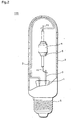
- Fig. 2 is a view, with portions broken away, of a metal halide lamp 100 having the arc tube 4.
- the metal halide lamp 100 which has a rated wattage of 150W, a total length of 140mm and the outer diameter of 40mm, includes an outer tube 2 with one end being closed and the other end being sealed by a stem 1. Referring to Fig. 2, two Monel stem wires 3 extend towards the inside of the outer tube 2 though the stem 1, and the second conductive members 15 of the arc tube 4 are connected to the stem wires 3.
- a base 5 is provided at the place where the outer tube 2 is sealed with the stem 1. Also, a predetermined volume of nitrogen gas is enclosed in the outer tube 2, in order to prevent the occurrence of discharge in the outer tube 2 due to a possible leakage in the arc tube 4.
- the reference numeral 6 refers to a known vicinity conductor that is used to start the lamp operation.
- a) metal halides such as dysprosium iodide (DyI 3 ) and sodium iodide (NaI)
- DyI 3 dysprosium iodide
- NaI sodium iodide
- mercury as a buffer
- argon gas neon gas, a mixture of them and other rare gases as starting gases.
- the feeder 12 for supplying electricity to the electrode 11 is sealed with the seal member 13, such as frit glass (with a thermal expansion coefficient of 6 ⁇ 10 -6 to 7 ⁇ 10 -6 ).
- the seal member 13 is introduced through a space between the capillary tube part 8 and the first conductive member 14 of the feeder 12, as described later, to an area 4mm to 6mm away from an end surface of the capillary tube part 8.
- the size of the space is within a range of 0.05mm to 0.07mm.
- the feeder 12 includes the first conductive member 14 and the second conductive member 15.
- the first conductive member 14 is a 20mm-long, rodded and halogen-resistant conductive cermet which is a sintered mixture of molybdenum and alumina (with the proportion of molybdenum and alumina 50% to 50%, by weight).
- the second conductive member 15 is a 20mm-long, rodded and heat-resistant substance, mainly composed of niobium, and has a greater mechanical strength than a conductive cermet.
- the first and the second conductive members are electrically connected by resistance welding or laser welding, so that their longitudinal shaft centers are placed in parallel, but not in a straight line. In other words, the ends of them are arranged side by side.
- a contact area where the first conductive member 14 electrically contacts with the second conductive member 15 increases in size. This improves their credibility as a feeder. Also, it is easier to weld them into such a rod-like shape than to weld the first conductive member 14 and the second conductive member 15 into a straight rod.
- the above conductive cermet As a material for the first conductive member 14, it is preferable to use the above conductive cermet whose thermal expansion coefficient is approximate to those of the capillary tube part 8 and the seal member 13. But this conductive cermet may be replaced with a conductive cermet having 40% of molybdenum and 60% of aluminum by weight, or a conductive cermet made of a sintered mixture of tungsten and aluminum. Tungsten may also be used as a material for the first conductive member 14.
- the second conductive member 15 As a material for the second conductive member 15, it is preferable to use niobium, which is thermal-resistant, flexible and has a thermal expansion coefficient approximate to the thermal expansion coefficient of the seal member 13. Other metals, such as tantalum, titanium, molybdenum and zirconium, may also be used. Obviously, the second conductive member 15 must be a heat-resistant metal so that it is not deformed as the temperature rises during the operation.
- the second conductive member 15 is chiefly made of niobium and contains several weight percentage of zirconium.
- the connecting portion of the first conductive member 14 and the second conductive member 15 is located outside the capillary tube part 8, being in the vicinity of an end surface of the capillary tube part 8, and is covered entirely with the seal member 13. Since the second conductive member 15 is fixed firmly at the end of the capillary tube part 8 by the seal member 13, and the connection between the first conductive member and the second conductive members is made stronger, it is less likely that the second conductive member 15 is broken off by external impact.
- the first conductive member 14 protrudes from the capillary tube part 8 by about 3mm.
- the seal member 13 covering the connecting portion of the first conductive member 14 and the second conductive member 15 is identical to and continuous to the seal member 13 that is introduced into the space between the capillary tube part 8 and the first conductive member 14.
- the shortest distance L is set substantially at 0mm.
- the second conductive member 15 effectively contacts the end surface of the capillary tube part 8.
- the inner diameter of the capillary tube part 8, D(mm), the outer diameter of the first conductive member 14, d1(mm) and the outer diameter of the second conductive member 15, d2(mm) should satisfy, d1+d2> D.
- the second conductive member 15 can be used as a stopper to determine the location of the electrode 11 in the main tube part 7 during the manufacture, which saves the need to provide the feeder with an additional stopper as has been required by a conventional manufacturing method. This results in the reduction in manufacturing cost, which improves production efficiency.
- the inner diameter D of the capillary tube part 8 is 1.0mm
- the outer diameter of the first conductive member 14 is 0.9mm
- the outer diameter of the second conductive member 15 is 0.5mm.
- the diameter of the first conductive member 14 is uniform along the rod.
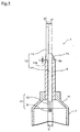
- Fig. 4 is a view, with portions broken away, which is used to explain the overview of a process of sealing the capillary tube part 8.
- the first conductive member 14 of the feeder 12 is inserted through a ringed frit glass block 130, and the electrode 11 that is connected to the tip of the first conductive member 14 is inserted into the capillary tube part 8 with an end to be closed facing upwards.
- the bottom surface of the ringed frit glass block 130 contacts to an end surface of the capillary tube part 8, as shown in Fig. 4, and an end surface 15a of the second conductive member 15 contacts the upside end surface of the frit glass block 130.
- the capillary tube part 8 With a heater arranged around the frit glass block 130, the capillary tube part 8, in this position, is heated at around 1500° , at which the frit glass block 130 melts down and turns into a liquid. As a result, the feeder 12 falls by the pull of gravity, so that the end surface 15a comes in contact with an end surface 8a of the capillary tube part 8, which determines an exact location of the feeder 12 and the electrode 11.
- a lamp included in a general light case was dropped perpendicularly from a point one-meter away from the floor so that the longitudinal axis of the lamp is laid in parallel to the floor.
- Such a metal halide lamp has the same construction as the metal halide lamp of the first embodiment which has a rated wattage of 150W, except that the feeder is made of tungsten and niobium which are connected together into a rod, and that the connecting part where tungsten and niobium are connected, or a part of the niobium portion, is inside the capillary tube part 8.
- the niobium portion arranged inside the capillary tube part 8 is completely covered by the seal member 13.
- An end surface of the niobium portion on the side facing the discharge space is situated 2mm away from an end surface of the seal member 13 on the side facing the discharge space.
- the luminous efficacy, correlated color temperature and general color rendering index Ra of the lamps of invention A, comparison A and comparison B are 901m/W, 4300K and 90, respectively.
- the metal halide lamp of the first embodiment has the feeder 12 including only the halogen-resistant first conductive member 14 in the capillary tube part 8, so that even if halides penetrate into a space between the capillary tube part 8 and the seal member 13 during the lamp operation, the feeder 12 is saved from the erosion by the halides. This prevents the occurrence of a possible leakage by the erosion, and as a result, the operating life can be extended.
- the breakage of the feeder 12 on external impact and vibration can be prevented, since the portion of the feeder 12 arranged outside the capillary tube part 8 is made of the second conductive member 15 having a greater mechanical strength, the strength of the connecting portion is increased with the seal member 13 covering at least a part of the connecting portion where the first conductive member 14 is connected to the second conductive member 15.
- a metal halide lamp of the second embodiment has the same structure except for a feeder in the arc tube 4.
- Fig. 5 is an enlarged cross-sectional view of a capillary tube part 8 of the arc tube 4 in the second embodiment.
- the connecting portion where the first conductive member 14 is connected to the second conductive member 17 is almost entirely covered by the seal member 13, so that the second conductive member 17 is supported securely by the capillary tube part 8.
- the size of an area where the first conductive member 14 is connected with the second conductive member 17 is within a range of 2.8mm 2 to 17mm 2 ; it may be 8.5mm 2 , for instance.
- the bottom surface of the second conductive member 17 substantially contacts to an end surface of the capillary tube part 8. It is preferable that the inner diameter D(mm)of the capillary tube part 8, (See Fig. 5) and the outer diameter d 3 (mm) of the second conductive member 17, (See Fig. 5) satisfy, d 3> D.
- the inner diameter D of the capillary tube part 8 is set at 1.0mm
- the outer diameter of the second conductive member 17 is set at 1.4mm.
- the second conductive member 17 can be used as a stopper to determine the location of the electrode 11 in the main tube part 7 during the manufacture effectively. This saves the need to provide an additional stopper to the feeder which was provided by conventional manufacturing methods, which reduces production cost and increases production efficiency.
- the first conductive member 14 of the feeder 16 of the metal halide lamp of the second embodiment that is placed inside the capillary tube part 8 is halogen-resistant. This being so, even if halides penetrate in between the capillary tube part 8 and the seal member 13 during the lamp operation, there is no risk of the feeder being eroded by halides. Therefore, it is possible to prevent the occurrence of leakage by halides, and thereby the operating life of the lamp is extended.
- a portion of the feeder 16 arranged outside the capillary tube part 8 which is the second conductive member 17 is made of niobium and has a greater mechanical strength than a conductive cermet, which is used as a material for the first conductive member 14.
- the first conductive member 14 is connected to the cylindrical second conductive member 17 inside the second conductive member 17, and the connecting portion where the first conductive member 14 is connected to the second conductive member 17 is at least partially covered by the seal member 13.
- the connecting portion is provided with a greater mechanical strength, which further reduces the possibility of the feeder 16 being broken off by external impact and vibration.
- the size of the contact area where the first conductive member 14 contacts the second conductive member 17 is increased, ensuring electrical connection between them.
- the size of the contact area increases, and as a result, resistance of the contact surface is reduced. This makes it easier to weld the first conductive member 14 and the second conductive member 17 together.
- the melted seal member 13 flows through the incision part 17b into the space between the capillary tube part 8 and the first conductive member 14 during the manufacture, which raises production efficiency.
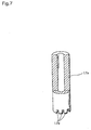
- Fig. 7 is a perspective view, with portions broken away, of the second conductive member 17a.
- three of incision part 17b are provided on the end surface of the second conductive member 17a that is facing towards the capillary tube part 8.
- Each of them has a depth of 0.2mm to 1.0mm and a width of 0.2mm to 1.0mm.
- the amount of the seal member 13 that is introduced in the circumference direction is equalized, which ensures the sealing for the first conductive member 14 and the capillary tube part 8.
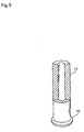
- Fig. 9 is a perspective view, with portion broken away, of the second conductive member 19.
- the connecting portion where the first conductive member 14 is connected to the second conductive member 19 is almost entirely covered by the seal member 13.
- the metal halide lamp of the third embodiment including the cylindrical second conductive member can achieve the same effects as in the case of the second embodiment, such as longer operating lifetime and resistance to impact. Also, with the presence of the fringe 20, which is provided at the end of the second conductive member 19 so as to substantially contacts to the end surface of the capillary tube part 8, it is less likely that the feeder 18 being broken by external impact and vibration in a direction vertical to the longitudinal direction of the second conductive member 19. This improves lamp's resistance to impact.
- the use of the ringed member 21 can reinforce the second conductive member 19, as does the fringe 20.
- the ringed member does not have to be conductive, which provides a wider choice of the material.
- the outer diameter of the ringed member 21 should be smaller than the outer diameter of the capillary tube part 8, as in the case of the fringe 20 of Fig. 8.
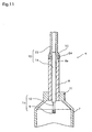
- Fig. 11 shows the construction of the capillary tube part 8 of the arc tube 4 in a metal halide lamp, which is the fourth embodiment.
- the fourth embodiment differs from the second and the third embodiments in that a taper 24 is provided at the end of the cylindrical second conductive member 23 of the feeder 22, and the end of the taper 24 is substantially connected to the end surface of the capillary tube part 8.
- the taper 24 flares outwardly (towards the capillary tube part 8), so that the inner rim of the taper 24 contacts the end surface of the capillary tube part 8 in the form of a line.
- the seal member 13 is supplied in a space between the first conductive member 14 and the taper 24 of the second conductive member 23.
- the other end of the arc tube 4 has the same construction.
- the metal halide lamp having the arc tube 4 with the stated construction can provide similar effects to those in the second embodiment; the metal halide lamp can operate for a longer lifetime and acquire stronger resistance to impact. Moreover, since the taper 24 is provided at the end of the second conductive member 23 and substantially contacts to the end surface of the capillary tube part 8, there is little possibility that the breakage of the feeder 22 occurs due to impact and vibration which are caused in a direction perpendicular to the longitudinal direction of the second conductive member 23. This gives the metal halide lamp more resistance to impact.
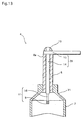
- Fig. 12 shows the construction of the capillary tube part 8 of the arc tube 4 of a metal halide lamp, which is the fifth embodiment.
- the second conductive member 26 of the feeder 25 includes a cylindrical part 28 which is made of niobium and has an inner diameter of 0.94mm, and a rod part 27 which is made of niobium and inserted from the above and connected to the cylindrical part 28.
- the arc tube 4 of the present embodiment is no different from that of the second embodiment.
- the rod part 27 of the second conductive member 26 is inserted into the cylindrical part 28 from the above to reach around the middle, so as to contact the end surface of the first conductive member 14.
- the first conductive member 14 is inserted at about 3mm away from the bottom of the cylindrical part 28. They are connected together into a rod.
- the first conductive member 14 and the second conductive member 26 are mechanically and electronically connected together by laser welding or resistant welding, which is performed on a specific area of the exterior of the cylindrical part 28 corresponding to the place where the first and second conductive members make contact.
- the capillary tube part 8 on the other end of the arc tube 4 has the same construction.
- the bottom surface of the cylindrical part 28 substantially contacts to the end surface 8a of the capillary tube part 8. It is preferable that the inner diameter D(mm) of the capillary tube part 8, and the outer diameter d 3(mm) of the cylindrical part 28 satisfy, d 3> D .
- the second conductive member 26 can be used as a stopper to determine the location of the electrode 11 in the main tube part 7 during the manufacture. This saves the need to provide an additional stopper to the feeder which is required by a conventional manufacturing method. This contributes to a reduction in production cost and an increase in production efficiency.
- the inner diameter D of the capillary tube part 8 is set at 1.0mm, and the outer diameter of the cylindrical part 28 is set at 1.4mm, so as to satisfy the above requirement.
- the metal halide lamp having the arc tube 4 with the stated construction can provide the same effects as the metal halide lamp of the second embodiment, increasing the operating life and resistance to impact.
- the end surface of the first conductive member 14 contacts to the end surface of the rod part 27, so that the contact area where the two members contact with each other increases in size, which ensures the electrical connection of them.
- the entire part of the second conductive member has a cylindrical shape, but a second conductive member may have a rod-like form if a connecting portion where the second conductive member is connected to the first conductive member 14 inserted has a cylindrical shape.
- the cylindrical part 28 of the fifth embodiment is made of niobium, but the same effects can be obtained when using a different material for the cylindrical part 28, including tantalum and molybdenum. It is not necessary that an identical material should be used for the rod part 27 and cylindrical part 28, as in the fifth embodiment.
- the first conductive member and the second conductive member, included in the feeder are connected together so that their respective longitudinal axis centers correspond or are arranged side by side. In the sixth embodiment, they are connected and cross at a right angle.
- a metal halide lamp of the sixth embodiment has the same construction as the embodiments 1 to 5.
- Fig. 13 is an enlarged cross-sectional view illustrating the construction of a capillary tube part 8 of the arc tube 4 in the metal halide lamp of the sixth embodiment.
- a feeder 29 includes a first conductive member 14 arranged inside the capillary tube part 8 and a second conductive member 15 placed perpendicular to the axial direction of the first conductive member 14.
- the end of the second conductive member 14 is connected to a protruding part of the first conductive member 14 that is protruding from the capillary tube part 8. Note that the other end of the arc tube 4 has the same construction.
- the metal halide lamp of the sixth embodiment can operate for a longer lifetime and acquire a greater resistance to impact, as in the case of the other embodiments.
- the first conductive member 14 and the second conductive member 15 are connected so that the longitudinal axis of the second conductive member 14 is positioned perpendicular to the longitudinal axial center of the second conductive member 15.
- a shorter metal halide lamp is obtained, which is shorter than the metal halide lamp of the first embodiment, where the end of the first conductive member 14 and the end of the second conductive member 15 are arranged side by side.
- the second conductive member 15, being substantially in contact with the end of the capillary tube part 8, serves as a stopper to determine the location of the electrode 11.
Applications Claiming Priority (2)
| Application Number | Priority Date | Filing Date | Title |
|---|---|---|---|
| JP2000338665 | 2000-11-07 | ||
| JP2000338665 | 2000-11-07 |
Publications (2)
| Publication Number | Publication Date |
|---|---|
| EP1205963A1 true EP1205963A1 (de) | 2002-05-15 |
| EP1205963B1 EP1205963B1 (de) | 2012-01-18 |
Family
ID=18813842
Family Applications (1)
| Application Number | Title | Priority Date | Filing Date |
|---|---|---|---|
| EP01309378A Expired - Lifetime EP1205963B1 (de) | 2000-11-07 | 2001-11-06 | Hochdruckentladungslampe und Bogenröhre |
Country Status (3)
| Country | Link |
|---|---|
| US (1) | US6650054B2 (de) |
| EP (1) | EP1205963B1 (de) |
| CN (2) | CN100521069C (de) |
Cited By (2)
| Publication number | Priority date | Publication date | Assignee | Title |
|---|---|---|---|---|
| WO2005124823A1 (en) * | 2004-06-14 | 2005-12-29 | Koninklijke Philips Electronics N.V. | Ceramic metal halide discharge lamp |
| EP2081214A1 (de) * | 2008-01-18 | 2009-07-22 | Flowil International Lighting (HOLDING) B.V. | Elektrodeneinheit für eine Hochdruck-Entladungslampe |
Families Citing this family (8)
| Publication number | Priority date | Publication date | Assignee | Title |
|---|---|---|---|---|
| US20030025455A1 (en) * | 2001-07-31 | 2003-02-06 | Alderman John C. | Ceramic HID lamp with special frame for stabilizing the arc |
| JP4153759B2 (ja) * | 2002-09-13 | 2008-09-24 | 松下電器産業株式会社 | 高圧放電ランプの製造方法 |
| JP4832717B2 (ja) * | 2003-12-22 | 2011-12-07 | パナソニック株式会社 | メタルハライドランプ、および照明装置 |
| JP4606281B2 (ja) * | 2004-10-14 | 2011-01-05 | 株式会社小糸製作所 | 放電ランプ装置用アークチューブ |
| US20060208641A1 (en) * | 2005-03-15 | 2006-09-21 | Takashi Maniwa | Cold-cathode fluorescent lamp having thin coat as electrically connected terminal, production method of the lamp, lighting apparatus having the lamp, backlight unit, and liquid crystal display apparatus |
| DE102005025155A1 (de) * | 2005-06-01 | 2006-12-07 | Patent-Treuhand-Gesellschaft für elektrische Glühlampen mbH | Hochdrucklampe und zugehöriges Betriebsverfahren für den Resonanzbetrieb von Hochdrucklampen im longitudinalen Mode und zugehöriges System |
| DE102007045071A1 (de) * | 2007-09-21 | 2009-04-02 | Osram Gesellschaft mit beschränkter Haftung | Hochdrucklampe und zugehöriges Betriebsverfahren für den Resonanzbetrieb von Hochdrucklampen im longitudinalen Mode und zugehöriges System |
| CN104747893A (zh) * | 2014-07-28 | 2015-07-01 | 李莹 | 密封性氧化铝陶瓷管 |
Citations (2)
| Publication number | Priority date | Publication date | Assignee | Title |
|---|---|---|---|---|
| US5424609A (en) * | 1992-09-08 | 1995-06-13 | U.S. Philips Corporation | High-pressure discharge lamp |
| EP1006560A2 (de) * | 1998-12-04 | 2000-06-07 | Toshiba Lighting & Technology Corporation | Durchführung für eine Hochdruckentladungslampe, Beleuchtungssystem mit Spannungsversorgung für eine solche Lampe |
Family Cites Families (7)
| Publication number | Priority date | Publication date | Assignee | Title |
|---|---|---|---|---|
| NL7612120A (nl) * | 1976-11-02 | 1978-05-05 | Philips Nv | Elektrische gasontladingslamp. |
| DE4242122A1 (de) * | 1992-12-14 | 1994-06-16 | Patent Treuhand Ges Fuer Elektrische Gluehlampen Mbh | Verfahren zur Herstellung einer vakuumdichten Abdichtung zwischen einem keramischen und einem metallischen Partner, insbesondere zur Anwendung bei der Herstellung eines Entladungsgefäßes für eine Lampe, sowie damit hergestellte Entladungsgefäße und Lampen |
| BE1008050A3 (nl) * | 1994-01-24 | 1996-01-03 | Philips Electronics Nv | Hoge-drukontladingslamp. |
| JP3318250B2 (ja) * | 1997-12-26 | 2002-08-26 | 松下電器産業株式会社 | 金属蒸気放電ランプ |
| JP3397145B2 (ja) * | 1998-09-18 | 2003-04-14 | ウシオ電機株式会社 | セラミック製ランプ |
| JP3275847B2 (ja) * | 1998-09-22 | 2002-04-22 | 松下電器産業株式会社 | 高圧金属蒸気放電灯 |
| JP2000285857A (ja) * | 1999-03-29 | 2000-10-13 | Toshiba Lighting & Technology Corp | 高圧放電灯 |
-
2001
- 2001-11-06 US US10/011,356 patent/US6650054B2/en not_active Expired - Lifetime
- 2001-11-06 EP EP01309378A patent/EP1205963B1/de not_active Expired - Lifetime
- 2001-11-07 CN CNB2005101310951A patent/CN100521069C/zh not_active Expired - Fee Related
- 2001-11-07 CN CNB011425555A patent/CN1264195C/zh not_active Expired - Fee Related
Patent Citations (2)
| Publication number | Priority date | Publication date | Assignee | Title |
|---|---|---|---|---|
| US5424609A (en) * | 1992-09-08 | 1995-06-13 | U.S. Philips Corporation | High-pressure discharge lamp |
| EP1006560A2 (de) * | 1998-12-04 | 2000-06-07 | Toshiba Lighting & Technology Corporation | Durchführung für eine Hochdruckentladungslampe, Beleuchtungssystem mit Spannungsversorgung für eine solche Lampe |
Cited By (2)
| Publication number | Priority date | Publication date | Assignee | Title |
|---|---|---|---|---|
| WO2005124823A1 (en) * | 2004-06-14 | 2005-12-29 | Koninklijke Philips Electronics N.V. | Ceramic metal halide discharge lamp |
| EP2081214A1 (de) * | 2008-01-18 | 2009-07-22 | Flowil International Lighting (HOLDING) B.V. | Elektrodeneinheit für eine Hochdruck-Entladungslampe |
Also Published As
| Publication number | Publication date |
|---|---|
| EP1205963B1 (de) | 2012-01-18 |
| US6650054B2 (en) | 2003-11-18 |
| CN100521069C (zh) | 2009-07-29 |
| CN1783420A (zh) | 2006-06-07 |
| CN1353446A (zh) | 2002-06-12 |
| CN1264195C (zh) | 2006-07-12 |
| US20020079841A1 (en) | 2002-06-27 |
Similar Documents
| Publication | Publication Date | Title |
|---|---|---|
| JP4798311B2 (ja) | 放電ランプ | |
| US5352952A (en) | High-pressure discharge lamp with ceramic discharge vessel | |
| JP4304902B2 (ja) | 高圧放電ランプ | |
| US6075314A (en) | Metal-halide lamp with specific lead through structure | |
| EP0722183A2 (de) | Hochspannungsentladungslampen | |
| EP1205963B1 (de) | Hochdruckentladungslampe und Bogenröhre | |
| KR100825132B1 (ko) | 고압 방전 램프 | |
| JP2008527677A (ja) | 高圧放電ランプ | |
| EP1058288B1 (de) | Metalldampfentladungslampe | |
| EP2122663B1 (de) | Hochdruckentladungslampe mit keramischem entladungsgefäss | |
| US20060049760A1 (en) | Metal halide lamp with ceramic discharge vessel | |
| US6815893B2 (en) | Metal halide lamp having a long lifespan | |
| HU214798B (hu) | Nagynyomású kisülőlámpa kerámia kisülőedénnyel | |
| EP0262979B1 (de) | Entladungsröhrenaufbau für Hochdruckentladungslampe | |
| JP2009032446A (ja) | 高圧放電ランプ | |
| EP1538661A2 (de) | Metallhalogenidlampe | |
| JP4791897B2 (ja) | セラミックメタルハライドランプおよび照明装置 | |
| JP4808552B2 (ja) | 自動車用放電ランプ | |
| JP5286536B2 (ja) | 高圧放電ランプおよび照明装置 | |
| JP4755024B2 (ja) | 放電ランプおよび放電ランプ装置 | |
| JP3576159B2 (ja) | 高圧放電ランプ | |
| JP2003297288A (ja) | セラミクス放電管を備えたメタルハライドランプ | |
| JP3540789B2 (ja) | 高圧放電ランプ | |
| KR20010023389A (ko) | 고압 가스 방전 램프 | |
| US20090072743A1 (en) | Electric discharge lamp |
Legal Events
| Date | Code | Title | Description |
|---|---|---|---|
| PUAI | Public reference made under article 153(3) epc to a published international application that has entered the european phase |
Free format text: ORIGINAL CODE: 0009012 |
|
| AK | Designated contracting states |
Kind code of ref document: A1 Designated state(s): AT BE CH CY DE DK ES FI FR GB GR IE IT LI LU MC NL PT SE TR |
|
| AX | Request for extension of the european patent |
Free format text: AL;LT;LV;MK;RO;SI |
|
| 17P | Request for examination filed |
Effective date: 20020613 |
|
| AKX | Designation fees paid |
Designated state(s): BE DE GB |
|
| 17Q | First examination report despatched |
Effective date: 20040128 |
|
| RAP1 | Party data changed (applicant data changed or rights of an application transferred) |
Owner name: PANASONIC CORPORATION |
|
| GRAP | Despatch of communication of intention to grant a patent |
Free format text: ORIGINAL CODE: EPIDOSNIGR1 |
|
| GRAS | Grant fee paid |
Free format text: ORIGINAL CODE: EPIDOSNIGR3 |
|
| GRAA | (expected) grant |
Free format text: ORIGINAL CODE: 0009210 |
|
| AK | Designated contracting states |
Kind code of ref document: B1 Designated state(s): BE DE GB |
|
| REG | Reference to a national code |
Ref country code: GB Ref legal event code: FG4D |
|
| REG | Reference to a national code |
Ref country code: DE Ref legal event code: R096 Ref document number: 60145979 Country of ref document: DE Effective date: 20120315 |
|
| REG | Reference to a national code |
Ref country code: DE Ref legal event code: R082 Ref document number: 60145979 Country of ref document: DE |
|
| PLBE | No opposition filed within time limit |
Free format text: ORIGINAL CODE: 0009261 |
|
| STAA | Information on the status of an ep patent application or granted ep patent |
Free format text: STATUS: NO OPPOSITION FILED WITHIN TIME LIMIT |
|
| 26N | No opposition filed |
Effective date: 20121019 |
|
| REG | Reference to a national code |
Ref country code: DE Ref legal event code: R097 Ref document number: 60145979 Country of ref document: DE Effective date: 20121019 |
|
| GBPC | Gb: european patent ceased through non-payment of renewal fee |
Effective date: 20121106 |
|
| PG25 | Lapsed in a contracting state [announced via postgrant information from national office to epo] |
Ref country code: GB Free format text: LAPSE BECAUSE OF NON-PAYMENT OF DUE FEES Effective date: 20121106 |
|
| PGFP | Annual fee paid to national office [announced via postgrant information from national office to epo] |
Ref country code: DE Payment date: 20151119 Year of fee payment: 15 |
|
| PGFP | Annual fee paid to national office [announced via postgrant information from national office to epo] |
Ref country code: BE Payment date: 20151111 Year of fee payment: 15 |
|
| PG25 | Lapsed in a contracting state [announced via postgrant information from national office to epo] |
Ref country code: BE Free format text: LAPSE BECAUSE OF NON-PAYMENT OF DUE FEES Effective date: 20161130 |
|
| REG | Reference to a national code |
Ref country code: DE Ref legal event code: R119 Ref document number: 60145979 Country of ref document: DE |
|
| PG25 | Lapsed in a contracting state [announced via postgrant information from national office to epo] |
Ref country code: DE Free format text: LAPSE BECAUSE OF NON-PAYMENT OF DUE FEES Effective date: 20170601 |
|
| REG | Reference to a national code |
Ref country code: BE Ref legal event code: MM Effective date: 20161130 |