EP1205819A2 - Process cartridge and image forming apparatus - Google Patents
Process cartridge and image forming apparatus Download PDFInfo
- Publication number
- EP1205819A2 EP1205819A2 EP01126703A EP01126703A EP1205819A2 EP 1205819 A2 EP1205819 A2 EP 1205819A2 EP 01126703 A EP01126703 A EP 01126703A EP 01126703 A EP01126703 A EP 01126703A EP 1205819 A2 EP1205819 A2 EP 1205819A2
- Authority
- EP
- European Patent Office
- Prior art keywords
- toner
- unit
- process cartridge
- development
- holding frame
- Prior art date
- Legal status (The legal status is an assumption and is not a legal conclusion. Google has not performed a legal analysis and makes no representation as to the accuracy of the status listed.)
- Granted
Links
- 238000000034 method Methods 0.000 title claims abstract description 77
- 238000011161 development Methods 0.000 claims abstract description 122
- 238000012546 transfer Methods 0.000 claims description 8
- 239000002699 waste material Substances 0.000 claims description 7
- 230000008878 coupling Effects 0.000 description 13
- 238000010168 coupling process Methods 0.000 description 13
- 238000005859 coupling reaction Methods 0.000 description 13
- 108091008695 photoreceptors Proteins 0.000 description 12
- 238000009434 installation Methods 0.000 description 6
- 238000012423 maintenance Methods 0.000 description 5
- 238000004519 manufacturing process Methods 0.000 description 4
- 229920002799 BoPET Polymers 0.000 description 3
- 239000005041 Mylar™ Substances 0.000 description 3
- 238000004140 cleaning Methods 0.000 description 2
- 239000006247 magnetic powder Substances 0.000 description 2
- 238000000926 separation method Methods 0.000 description 2
- 239000002131 composite material Substances 0.000 description 1
- 230000008021 deposition Effects 0.000 description 1
- 238000013461 design Methods 0.000 description 1
- 238000005192 partition Methods 0.000 description 1
- 239000011369 resultant mixture Substances 0.000 description 1
- 238000004804 winding Methods 0.000 description 1
Images


Classifications
-
- G—PHYSICS
- G03—PHOTOGRAPHY; CINEMATOGRAPHY; ANALOGOUS TECHNIQUES USING WAVES OTHER THAN OPTICAL WAVES; ELECTROGRAPHY; HOLOGRAPHY
- G03G—ELECTROGRAPHY; ELECTROPHOTOGRAPHY; MAGNETOGRAPHY
- G03G15/00—Apparatus for electrographic processes using a charge pattern
- G03G15/06—Apparatus for electrographic processes using a charge pattern for developing
- G03G15/08—Apparatus for electrographic processes using a charge pattern for developing using a solid developer, e.g. powder developer
- G03G15/0896—Arrangements or disposition of the complete developer unit or parts thereof not provided for by groups G03G15/08 - G03G15/0894
Definitions
- the present invention relates to a detachable process cartridge for use in image forming apparatuses, such as copying machines, printers and facsimile machines, and also relates to image forming apparatuses using this process cartridge.
- Image forming apparatuses such as copying machines, printers and facsimile machines, form an image through an exposure process of forming an electrostatic latent image by exposure of the surface of a photoreceptor, such as a photosensitive drum and a photosensitive belt, to light; a development process of visualizing the formed electrostatic latent image by deposition of toner; a transfer process of transferring a toner image formed on the photoreceptor surface by development to a predetermined sheet; and a fixing process of fixing the toner image transferred to the sheet by application of heat.
- the above exposure, development and transfer processes are sequentially carried out at an exposure section, a development section and a transfer section, respectively, which are provided on the periphery of the photoreceptor.
- a cleaning section for removing toner remaining on the photoreceptor surface after the transfer process and a charging section for uniformly charging the surface before exposure are provided on the periphery of the photoreceptor.
- Image forming apparatuses of this type are mainly classified into two kinds of structures according to the maintenance methods.
- the first structure is a CRU (Customer Replaceable Unit) structure whose maintenance is performed mostly by the user.
- the second structure is an SRU (Serviceman Replaceable Unit) structure whose principal maintenance is carried out by a special serviceman.
- process means such as the above-mentioned development section, charging section and cleaning section, for performing the respective processes with respect to the photoreceptor are constructed as cartridges (process cartridges) which are attachable and detachable to/from the periphery of the photoreceptor in the main body of the apparatus.
- process cartridges process cartridges
- Miner troubles are solved by making simple adjustments.
- a severe trouble occurs, a corresponding cartridge as a unit is replaced.
- the development section for the development process is constructed by a development roller that is adjoined the surface of the photoreceptor to face the photoreceptor and rotates about an axis parallel to the surface, and agitating means provided on the side opposite to the development roller.
- the development roller is a magnet roller incorporating a magnet.
- Toner for use in development is mixed with a carrier made of a magnetic powder and agitated by the action of the agitating means, and the resultant mixture is used as a developer.
- the toner is deposited on the entire surface of the development roller and transferred to a section opposing the photoreceptor.
- the toner is attracted and moved to an electrostatic latent image formed on the surface of the photoreceptor, thereby forming a toner image.
- the process cartridge of the development section is constructed by integrating a development unit comprising the development roller and agitating means and a toner unit including a container for containing toner for development and toner supply means as disclosed in Japanese Patent Application Laid-Open Nos. 5-197227/1993 and 2-141777/1990.
- a development unit comprising the development roller and agitating means
- a toner unit including a container for containing toner for development and toner supply means as disclosed in Japanese Patent Application Laid-Open Nos. 5-197227/1993 and 2-141777/1990.
- image forming apparatus of the SRU structure many of process means including the development section are highly accurately positioned and fixed on the periphery of the photoreceptor in the main body of the apparatus.
- This structure has been widely adopted by image forming apparatuses, such as apparatuses serving as copying machines exclusively, which are designed to meet a demand for supply of a large volume of good quality printed matter at a low unit cost.
- image forming apparatuses of the SRU structure can handle various kinds of troubles by adjustments and replacement of the respective process means which are carried out by periodical maintenance work of special servicemen, thereby keeping good image quality for a long time.
- toner replacement is performed by detaching the fixed toner unit comprising the toner containing space and the toner supply means from the development section.
- An object of the present invention is to provide a process cartridge capable of certainly achieving separation/coupling of a development unit and a toner unit with a simple structure and realizing sharing of a development section between the CRU structure and the SRU structure with high accuracy without making the manufacturing processes complicated or increasing the manufacturing costs. It is also an object of the present invention to provide an image forming apparatus implemented using this process cartridge.
- a process cartridge comprises: a toner unit including a toner containing space and a toner supply section; a development unit including a developing device; and a holding frame including a fixture section for the development unit and an accepting section for the toner unit, and is characterized in that the process cartridge is constructed selectively in a first arrangement in which the toner unit is fixed in a predetermined position in the accepting section of the holding frame or in a second arrangement in which the toner unit is detachably installed in the predetermined position.
- the development unit is fixed, the holding frame having an accepting section for the toner unit is provided, and the toner unit is fixed in the accepting section of this holding frame.
- the process cartridge can correspond to the CRU structure by the first arrangement in which the toner unit and the development unit are integrated through the holding frame.
- the process cartridge can correspond to the SRU structure by the second arrangement in which the toner unit is detachably installed in the accepting section of the holding frame integrated with the development unit. Accordingly, sharing of the process cartridge for use in the development process is realized.
- a process cartridge according to the present invention is characterized in that the holding frame includes a fixture section for fixing the toner unit to the predetermined position, and guide sections for guiding the toner unit to the predetermined position.
- a process cartridge according to the present invention is characterized in that the holding frame includes a guide section for guiding itself to an appropriate position in an image forming apparatus main body in which the process cartridge is to be installed, and a fixture section for fixing itself to the appropriate position.
- the fixture section and guide sections formed on the holding frame by selectively using the fixture section and guide sections formed on the holding frame, it is possible to easily realize the CRU structure where the holding frame in which the development unit and the toner unit are integrated is attached and detached with respect to the main body of the image forming apparatus and the SRU structure where the toner unit is attached and detached with respect to the holding frame which is fixed to the main body of the image forming apparatus together with the development unit.
- An image forming apparatus comprises a receiving section for receiving a holding frame of a process cartridge of the present invention constructed in the first arrangement, and is characterized by replacement of toner and developer performed by detachment and attachment of the holding frame with respect to the receiving section.
- An image forming apparatus is characterized by fixing a holding frame of a process cartridge of the present invention constructed in the second arrangement to a predetermined position therein, and replacement of toner performed by detachment and attachment of the holding frame with respect to the holding frame.
- a process cartridge comprises: a toner unit including a toner containing space and a toner supply section; and a development unit including a developing device, and is characterized in that the process cartridge is constructed selectively in a third arrangement in which the toner unit and the development unit are fixed or in a fourth arrangement in which the toner unit and the development unit are detachably attached.
- the process cartridge can correspond to the CRU structure by the third arrangement in which the development unit and the toner unit are integrated by fixation. Moreover, the process cartridge can correspond to the SRU structure by the fourth arrangement in which the development unit and the toner unit are mutually attachable and detachable. Accordingly, sharing of the process cartridge for use in the development process is realized.
- a process cartridge according to the present invention is characterized in that the toner unit further comprises a waste toner storing space for storing toner collected as non-transfer toner.
- An image forming apparatus comprises a receiving section for receiving a process cartridge of the present invention constructed in the third arrangement and fourth arrangement, and is characterized in that the toner unit and the development unit are attachable and detachable as one unit or separate units with respect to the receiving section.
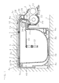
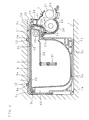
- FIGS. 1 and 2 are sectional side views showing the structures of process cartridges according to the present invention.
- a process cartridge according to the present invention is constructed by a development unit 2, a toner unit 3, and a holding frame 4 that is formed as a separate body with respect to the above units.
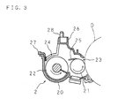
- FIG. 3 is a sectional side view of the development unit 2.
- the development unit 2 is constructed by installing and supporting a development roller 21 and an agitating roller 22 that rotate about mutually parallel axes in a housing 20.
- the development roller 21 is a magnet roller incorporating a magnet.
- the development roller 21 is disposed so that a part of its circumferential surface appears over the entire length from a window opening 23 formed on one side of the housing 20.
- the agitating roller 22 is positioned in an agitating space which is formed to have a circular-arc-shaped base below a toner opening 24 that opens upward.
- the window opening 23 is formed so that the circumferential surface of the development roller 21 appearing therefrom faces the circumferential surface of a photosensitive drum D indicated by the alternate long and two short dashes line in FIG. 3.
- the toner opening 24 is formed to receive toner for development supplied from the toner unit 3 as to be described later.
- the development unit 2 constructed as described above distributes toner introduced from the toner opening 24 into the housing 20 in the axial direction (a direction perpendicular to the plane of the paper) by rotation of the agitating roller 22 constructed as a screw roller while mixing and agitating the toner and a carrier made of a magnetic powder.
- the development unit 2 deposits the toner evenly on the circumferential surface of the development roller 21 and transfers the toner by the rotation of the development roller 21.
- the toner thus transferred is attracted and moved to an electrostatic latent image formed on the surface of the facing photosensitive drum D at a section where the development roller 21 appears from the window opening 23, thereby visualizing the electrostatic latent image. Meanwhile, the carrier and toner which were not attracted and remain on the circumferential surface of the development roller 21 are removed by the function of a scraper 25 attached slidably on the downstream side of the circumferential surface, and moved back into the housing 20 for reuse.
- the development unit 2 constructed as described above includes a supporting edge 26 projecting upward on one side of the toner opening 24 that opens at an upper portion of the housing 20 and a supporting edge 27 projecting sideways on the other side of the toner opening 24, and positioning pins 28 are provided on the upper face of the supporting edge 26 to project from a plurality of points in a cross direction.
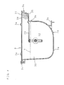
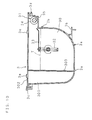
- FIG. 4 is a sectional side view of the toner unit 3. As shown in FIG. 4, the toner unit 3 is constructed by connecting a small-volume toner supply space 31 to one side of the upper portion of a large-volume toner containing space 30 having a pot-like cross section.
- toner T for use in development is stored in the toner containing space 30, in a predetermined depth from the bottom face.
- an agitator 32 as agitating means is installed laterally at substantially the center in the toner containing space 30.
- a highly elastic Mylar blade 33 is attached to one end of a blade body formed to protrude from both sides of a spindle. The Mylar blade 33 rotates in the direction indicated by an arrow in FIG. 4 so as to agitate the toner T.
- the Mylar blade 33 is constructed so as to feed an appropriate amount of the toner T into the toner supply space 31.
- a supply roller 34 constructed as a sponge roller by winding a sponge round the entire outer circumference is installed laterally.
- a toner outlet 35 through the bottom face is formed below the supply roller 34, on a side away from the toner containing space 30.
- the supply roller 34 rotates in the direction indicated by an arrow in FIG. 4.
- the supply roller 34 acts to successively output through the toner outlet 35 the toner T fed into the toner supply space 31 by the rotation of the agitator 32.
- a pair of support legs 3a, 3a are provided on the outside of the toner unit 3 thus constructed so that they protrude from the lower face of the toner containing space 30.
- a pair of guide protrusions 3b, 3b are provided on upper and lower portions of one side face, while a guide protrusion 3c is formed to protrude from an upper edge of the other side face.
- a guide protrusion 3d is formed to protrude from a side face of the toner supply space 31.
- short wide fixture seats 3e, 3e are provided on the upper face of the toner unit 3 to protrude from two locations appropriately separated in the cross direction of the toner containing space 30.
- FIG. 5 is a sectional side view of the holding frame 4.
- the holding frame 4 has a first accepting section 40 capable of accepting the toner containing space 30 of the toner unit 3. Moreover, a second accepting section 41 capable of accepting the toner supply space 31 is provided on one side of the first accepting section 40.
- the holding frame 4 is constructed as a frame whose front side is entirely open.
- Set-screw holes 42, 42 are formed in the upper face of the first accepting section 40 to run through the upper face at positions corresponding to the respective fixture seats 3e, 3e on the upper face of the toner unit 3. Additionally, a communicating hole 43 running through the bottom face of the second accepting section 41 is formed in an end of the bottom face at a position corresponding to a position on the lower face of the toner supply space 31 where the toner outlet 35 is formed.
- a fixture flange 44 for fixing the development unit 2 is formed on an outside upper portion of the end wall of the second accepting section 41 so that it projects outward.
- a positioning hole 44a is formed in the fixture flange 44 to run through a position corresponding to the positioning pin 28 protruding from the support edge 26 on the upper portion of the development unit 2.
- a pair of support legs 4a, 4a are provided to protrude from the outer side of the holding frame 4 at positions below the first accepting section 40.
- a pair of fixture flanges 4b, 4b are provided on both sides of the set-crews 42, 42 to protrude from the outer side of the holding frame 4.
- a pair of guide sections 4c, 4c are formed on both sides of these fixture flanges 4b, 4b.
- the fixture flanges 4b, 4b are flat plate-like members whose front faces coincide with the plane of the paper.
- a set-screw hole running through the front and rear faces is formed at substantially the center of each fixture flange 4b.
- each of the guide sections 4c, 4c is constructed by extending two protruding bars that face each other with a predetermined space therebetween in the cross direction along a direction orthogonal to the plane of the paper.
- the process cartridge according to the present invention is a combination of the development unit 2, toner unit 3 and holding frame 4 as described above, and is selectively used in the first arrangement shown in FIG. 1 or the second arrangement shown in FIG. 2.
- the development unit 2 is supported and fixed by a fixture flange 44 of the holding frame 4.
- the upper face of the support edge 26 of the development unit 2 is placed in position by bringing the upper face into contact with the lower face of the fixture flange 44.
- the upper face of the support edge 27 is placed in position by bringing the upper face into contact with the lower face of the second accepting section 41.
- the positioning pin 28 protruding from the support edge 26 is placed in position by fitting it into the positioning hole 44a running through the fixture flange 44. Accordingly, as shown in the drawings, the toner opening 24 formed in the development unit 2 is positioned below the communicating hole 43 formed in the bottom face of the second accepting section 41 of the holding frame 41.
- the toner unit 3 is fixed in the holding frame 4 in the first arrangement shown in FIG. 1, while it is detachably installed in the holding frame 4 in the second arrangement shown in FIG. 2.
- the toner unit 3 is inserted into the holding frame 4.
- the fixture seats 3e, 3e protruding from the upper positions of the toner containing space 30 are set inside of the set-screw holes 42, 42 formed in the upper face of the holding frame 4.
- Set-screws 5, 5 inserted into these set-screw holes 42, 42 from the upper part of the holding frame 4 are screwed into the screw holes formed in the center of the respective fixture seats 3e, 3e.
- the support legs 3a, 3a protruding from the lower positions of the toner containing space 30 come into contact with the bottom face of the first accepting section 40.
- the guide protrusions 3b, 3b and guide edge 3c protruding from both side faces of the toner containing space 30 come into contact with the inner face of the first accepting section 40.
- the guide protrusion 3d protruding from the side face of the toner supply space 31 comes into contact with the inner face of the second accepting section 41. Accordingly, the toner unit 3 is accurately placed in a predetermined position in the holding frame 4.
- the toner outlet 35 running through the bottom face of the toner supply space 31 is positioned above the communicating hole 43 running through the bottom face of the second accepting section 41 of the holding frame 4.
- the toner T outputted through the toner outlet 35 by the rotation of the supply roller 34 in the toner supply space 31 falls through the communicating hole 43.
- the toner T is surely supplied to the development unit 2 through the toner opening 24 positioned below the communicating hole 43.
- Such a process cartridge of the first arrangement is used by installing the holding frame 4 comprising the development unit 2 and the toner unit 3 integrally mounted therein in a receiving recession 1 provided at an appropriate position in the main body of the image forming apparatus.
- Guide rails 10, 10 formed at appropriate positions on the top face of the recession 1 are fitted into the gaps in the guide sections 4c, 4c extended in the depth direction on the upper face of the holding frame 4.
- the installation is achieved by pushing the holding frame 4 in the depth direction by the functions of these guides.
- the holding frame 4 installed in such a manner is placed in position in the vertical direction by bringing a pair of support legs 4a, 4a protruding from the lower outer face into contact with the bottom face of the recession 1. Further, the holding fame 4 is placed in position in the right-left direction by the guide rails 10, 10 fitted into the gaps in the guide sections 4c, 4c. As a result, as shown in FIG. 3, the circumferential face of the development roller 21 appearing from the window opening 23 on one side of the development unit 2 adjoins and faces the surface of the photosensitive drum D. Moreover, it is possible to certainly perform the above-described development operation of the development unit 2.
- the process cartridge of the first arrangement is applicable to image forming apparatuses having the above-mentioned CRU structure.
- installation of the toner unit 3 is achieved by pushing the toner unit 3 in the depth direction from an opening in the front side into the holding frame 4.
- the support legs 3a, 3a protruding from the lower positions of the toner containing space 30 come into contact with the bottom face of the first accepting section 40.
- the fixture seats 3e, 3e protruding from the upper positions come into contact with the top face of the first accepting section 40.
- the toner unit 3 is placed in position in the vertical direction.
- the guide protrusions 3b, 3b and the guide edge 3c protruding from both side faces of the toner containing space 30 respectively come into contact with the inner face of the first accepting section 40.
- the guide protrusion 3d protruding from the side face of the toner supply space 31 comes into contact with the inner face of the second accepting section 41. Accordingly, the toner unit 3 is placed in position in the right-left direction. With the pushing of the toner unit 3 by these guides, the toner unit 3 is accurately placed in a predetermined position in the holding frame 4. Note that the fixture seats 3e, 3e are used as the above-mentioned guide sections.
- Such a process cartridge of the second arrangement is used by fixing the holding frame 4 integrated with the development unit 2 in the receiving recession 1 provided at an appropriate position in the main body of the image forming apparatus.
- the support legs 4a, 4a protruding from the lower portion of the holding frame 4 are supported by bringing them into contact with the bottom face of the recession 1.
- the fixture flanges 4b, 4b protruding from the upper portion of the holding frame 4 are respectively aligned with fixture seats 11, 11 hanged from the top face of the recession 1.
- the set-screws 12, 12 inserted through the screw holes in the center of the respective fixture flanges 4b, 4b are screwed into the fixture seats 11, 11, respectively.
- the process cartridge of the second arrangement is applicable to image forming apparatuses having the above-mentioned SRU structure.
- a toner unit 3 for replacement is installed with high positioning accuracy by the above-mentioned guide function associated with the holding frame 4.
- the toner outlet 35 running through the bottom face of the toner supply space 31 is positioned above the communicating hole 43 formed in the bottom face of the second accepting section 41 of the holding frame 4.
- the toner T outputted by the rotation of the supply roller 34 in the toner supply space 31 falls through the toner outlet 35 and the communicating hole 43.
- the toner T is surely supplied into the development unit 2 through the toner opening 24 positioned below the communicating hole 43.
- the guide sections 4c, 4c protruding from the upper face of the holder flame 4 can be used to limit the movement of the holding frame 4 in the vertical direction by bringing the guide sections 4c, 4c into contact with the top face of the recession 1.
- the fixture flanges 4b, 4b protruding from the upper face of the holding frame 4 can be used as stoppers for positioning in the depth direction by bringing the fixture flanges 4b, 4b into contact with the circumferential edge of the recession 1.
- FIG. 6 is a sectional side view of the development unit 2 and toner unit 3 according to the third arrangement.
- a pair of guide sections 4c, 4c are provided to protrude from the upper part of the toner unit 3, and a first guide protrusion 30e is formed to extend in the direction of the development unit 2.
- a first coupling section 20a to be coupled with the first guide protrusion 30e is provided at an upper portion of the development unit 2.
- a second guide protrusion 30d is formed at substantially the center of the toner unit 3 to extend in the direction of the development unit 2, and correspondingly a second coupling section 20c to be coupled with the second guide protrusion 30d is formed at substantially the center of the development unit 2.
- the first guide protrusion 30e, the first coupling section 20a, the second guide protrusion 30d and the second coupling section 20c extend in a direction perpendicular to the plane of the paper.
- the toner unit 3 is installed by inserting the first guide protrusion 30e and second guide protrusion 30d of the toner unit 3 in a sliding manner into the first coupling section 20a and the second coupling section 20c of the development unit 2. Screw holes, not shown, are formed coaxially at predetermined positions in the first guide protrusion 30e and first coupling section 20a to couple them with a screw 20d.
- a pair of fixture flanges 20d, 20d are provided to protrude from upper portion of the development unit 2.
- the fixture flanges 20d, 20d are flat plate-like members whose front faces coincide with the plane of the paper, and a set-screw hole running through the front and back surfaces is formed at the center of each fixture flange 20d.
- FIG. 7 is a side sectional view of the development unit 2 and toner unit 3 according to the fourth arrangement.
- the fundamental structures are the same as those of the development unit 2 and toner unit 3 according to the third arrangement shown in FIG. 6.
- the toner unit 3 is installed by sliding the first guide protrusion 30e and second guide protrusion 30d of the toner unit 3 into the first coupling section 20a and second coupling section 20c of the development unit 2, without using the screw 20d.
- FIG. 8 is a side sectional view showing the structure of the third arrangement of the process cartridge according to the present invention.
- the toner unit 3 and the development unit 2 are coupled by the screw 20b.
- the process cartridge of the third arrangement integrated in this manner is used by installing it in the receiving recession 1 provided at an appropriate position in the main body of the image forming apparatus.
- the toner unit 3 is installed by fitting the guide rails 10, 10 into the gaps in the guide sections 4c, 4c and pushing the toner unit 3 and development unit 2 in the depth direction by the functions of these guides.
- the toner unit 3 and development unit 2 installed in this manner are placed in position in the vertical direction by bringing a pair of support legs 3a, 3a protruding from the lower outer face into contact with the bottom face of the recession 1. Further, the toner unit 3 and development unit 2 are placed in position in the right-left direction by the guide rails 10, 10 fitted into the gaps in the guide sections 4c, 4c. As a result, as shown in FIG. 3, the circumferential face of the development roller 21 appearing from the window opening 23 on one side of the development unit 2 adjoins and faces the surface of the photosensitive drum D. Moreover, it is possible to certainly perform the above-described development operation of the development unit 2.
- the process cartridge of the third arrangement is applicable to image forming apparatuses having the above-mentioned CRU structure.
- FIG. 9 is a side sectional view showing the structure of the fourth arrangement of the process cartridge according to the present invention.
- the toner unit 3 in the fourth arrangement is installed by inserting the first guide protrusion 30e and second guide protrusion 30d of the toner unit 3 in a sliding manner into the first coupling section 20a and second coupling section 20c of the development unit 2.
- the toner unit 3 is placed in position in the vertical direction by bringing the support legs 3a, 3a protruding at the lower positions of the toner containing space 30 into contact with the bottom face of the recession 1.
- the toner unit 3 is placed in position in the right-left direction by respectively bringing the guide protrusions 3b, 3b and the guide edge 3c protruding from both side faces of the toner containing space 30 into contact with the inner face of the recession 1. With the pushing of the toner unit 3 by these guides, the toner unit 3 is accurately installed in a predetermined position.
- Such a process cartridge of the fourth arrangement is used by fixing the development unit 2 in the receiving recession 1 provided at an appropriate position in the main body of the image forming apparatus.
- the fixture flanges 20d, 20d are respectively aligned with the fixture seats 11, 11 hanged from the top face of the recession 1.
- the set-screws 12, 12 inserted through the screw holes in the center of these fixture flanges 20d, 20d are screwed into the fixture seats 11, 11, respectively. Consequently, the development unit 2 is fixed.
- the process cartridge of the fourth arrangement is applicable to image forming apparatuses having the above-mentioned SRU structure.
- Embodiment 2 has the above-described structures, and, since other structures and functions are the same as those of Embodiment 1, the corresponding parts are designated with the same reference numbers and the detailed explanation thereof is omitted.
- FIG. 10 is a sectional side view of the toner unit 3 according to Embodiment 3.
- the toner unit 3 according to Embodiment 3 is constructed by two independent spaces 2, namely, the toner containing space 30 and a waste toner storing space 301.
- the toner containing space 30 and the waste toner storing space 301 are separated by a partition wall 303.
- the ceiling portion of the waste toner storing space 301 has a toner collecting opening 302. Toner collected as non-transfer toner is collected in the waste toner storing space 301 via the toner collecting opening 302.
- the toner unit 3 having the waste toner storing space 301 described in Embodiment 3 may be applied to the toner units 3 mentioned in Embodiments 1 and 2.
- Embodiment 3 has the above-described structures, and, since other structures and functions are the same as those of Embodiments 1 and 2, the corresponding parts are designated with the same reference numbers and the detailed explanation thereof is omitted.
Landscapes
- Physics & Mathematics (AREA)
- General Physics & Mathematics (AREA)
- Electrophotography Configuration And Component (AREA)
- Dry Development In Electrophotography (AREA)
- Photographic Developing Apparatuses (AREA)
Abstract
Description
Moreover, a cleaning section for removing toner remaining on the photoreceptor surface after the transfer process and a charging section for uniformly charging the surface before exposure are provided on the periphery of the photoreceptor.
Moreover, an
Moreover, the
Claims (8)
- A process cartridge comprising a toner unit (3) including a toner containing space (30) and a toner supply section (31); and a development unit (2) including a developing device, characterizedby comprising a holding frame (4) including a fixture section (44) for said development unit (2) and an accepting section (40) for said toner unit (3), andin that said process cartridge is constructed selectively in a first arrangement in which said toner unit (3) is fixed in a predetermined position in the accepting section (40) of said holding frame (4) or in a second arrangement in which said toner unit (3) is detachably installed in said predetermined position.
- The process cartridge of claim 1, wherein said holding frame (4) includes a fixture section (42) for fixing said toner unit (3) to said predetermined position, and guide sections (40, 41) for guiding said toner unit (3) to said predetermined position.
- The process cartridge of claim 1 or 2, wherein said holding frame (4) includes a guide section (4c) for guiding itself to an appropriate position in an image forming apparatus main body in which said process cartridge is to be installed, and a fixture section (4b) for fixing itself to said appropriate position.
- An image forming apparatus comprising a receiving section (1) for receiving a holding frame (4) of a process cartridge of any one of claims 1 through 3 constructed in said first arrangement, wherein replacement of toner and developer is performed by detachment and attachment of said holding frame (4) with respect to said receiving section (1).
- An image forming apparatus, wherein a holding frame (4) of a process cartridge of any one of claims 1 through 3 constructed in said second arrangement is fixed in a predetermined position therein, and replacement of toner is performed by detachment and attachment of said toner unit (3) with respect to said holding frame (4).
- A process cartridge comprising a toner unit (3) including a toner containing space (30) and a toner supply section (31); and a development unit (2) including a developing device, characterized in thatsaid process cartridge is constructed selectively in a third arrangement in which said toner unit (3) and said development unit (2) are fixed or in a fourth arrangement in which said toner unit (3) and said development unit (2) are detachably attached.
- The process cartridge of claim 1 or 6, characterized in that said toner unit (3) further comprises a waste toner storing space (301) for storing toner collected as non-transfer toner.
- An image forming apparatus, characterized by comprising a receiving section (1) for receiving a process cartridge of claim 6 constructed in said third arrangement and fourth arrangement, and characterized in that said toner unit (3) and said development unit (2) are attachable and detachable as one unit or separate units with respect to said receiving section (1).
Applications Claiming Priority (2)
| Application Number | Priority Date | Filing Date | Title |
|---|---|---|---|
| JP2000342712 | 2000-11-09 | ||
| JP2000342712A JP3572482B2 (en) | 2000-11-09 | 2000-11-09 | Process cartridge and image forming apparatus |
Publications (3)
| Publication Number | Publication Date |
|---|---|
| EP1205819A2 true EP1205819A2 (en) | 2002-05-15 |
| EP1205819A3 EP1205819A3 (en) | 2006-03-22 |
| EP1205819B1 EP1205819B1 (en) | 2010-04-21 |
Family
ID=18817207
Family Applications (1)
| Application Number | Title | Priority Date | Filing Date |
|---|---|---|---|
| EP01126703A Expired - Lifetime EP1205819B1 (en) | 2000-11-09 | 2001-11-08 | Process cartridge and image forming apparatus |
Country Status (5)
| Country | Link |
|---|---|
| US (1) | US6603940B2 (en) |
| EP (1) | EP1205819B1 (en) |
| JP (1) | JP3572482B2 (en) |
| CN (1) | CN1141625C (en) |
| DE (1) | DE60141879D1 (en) |
Families Citing this family (4)
| Publication number | Priority date | Publication date | Assignee | Title |
|---|---|---|---|---|
| US20030078614A1 (en) * | 2001-10-18 | 2003-04-24 | Amr Salahieh | Vascular embolic filter devices and methods of use therefor |
| JP2004206070A (en) * | 2002-10-31 | 2004-07-22 | Hitachi Ltd | Electrophotographic equipment |
| JP4738761B2 (en) * | 2004-06-04 | 2011-08-03 | 株式会社沖データ | Process cartridge and image forming apparatus |
| JP2007086392A (en) * | 2005-09-22 | 2007-04-05 | Fuji Xerox Co Ltd | Image forming apparatus |
Citations (2)
| Publication number | Priority date | Publication date | Assignee | Title |
|---|---|---|---|---|
| JPH02141777A (en) | 1988-11-22 | 1990-05-31 | Konica Corp | Color image forming device |
| JPH05197227A (en) | 1991-09-06 | 1993-08-06 | Xerox Corp | Electric connector for electrophotographic printing apparatus |
Family Cites Families (9)
| Publication number | Priority date | Publication date | Assignee | Title |
|---|---|---|---|---|
| JPS63220286A (en) * | 1987-03-10 | 1988-09-13 | Fuji Xerox Co Ltd | Developing device |
| US4974023A (en) * | 1988-06-23 | 1990-11-27 | Sharp Kabushiki Kaisha | Developing device for copier |
| JP3116583B2 (en) * | 1992-07-17 | 2000-12-11 | ブラザー工業株式会社 | Developer supply device |
| JP2918081B2 (en) * | 1992-09-22 | 1999-07-12 | 株式会社日立製作所 | Developing device and developer cartridge |
| JP3073102B2 (en) * | 1992-09-28 | 2000-08-07 | 富士通株式会社 | Process cartridge and image forming apparatus |
| JPH07319368A (en) * | 1994-03-30 | 1995-12-08 | Canon Inc | Toner cartridge, process cartridge, and electrophotographic image forming apparatus |
| JPH0836292A (en) * | 1994-07-25 | 1996-02-06 | Hitachi Ltd | Development device |
| JP3421545B2 (en) * | 1997-08-04 | 2003-06-30 | 株式会社日立製作所 | Developing device and image forming apparatus provided with the same |
| JP3639731B2 (en) * | 1998-08-31 | 2005-04-20 | キヤノン株式会社 | Method for stopping developer feeding member during distribution of development unit and method for stopping developer feeding member during distribution of image forming apparatus |
-
2000
- 2000-11-09 JP JP2000342712A patent/JP3572482B2/en not_active Expired - Fee Related
-
2001
- 2001-11-06 US US09/985,896 patent/US6603940B2/en not_active Expired - Lifetime
- 2001-11-08 EP EP01126703A patent/EP1205819B1/en not_active Expired - Lifetime
- 2001-11-08 DE DE60141879T patent/DE60141879D1/en not_active Expired - Lifetime
- 2001-11-09 CN CNB011378972A patent/CN1141625C/en not_active Expired - Fee Related
Patent Citations (2)
| Publication number | Priority date | Publication date | Assignee | Title |
|---|---|---|---|---|
| JPH02141777A (en) | 1988-11-22 | 1990-05-31 | Konica Corp | Color image forming device |
| JPH05197227A (en) | 1991-09-06 | 1993-08-06 | Xerox Corp | Electric connector for electrophotographic printing apparatus |
Also Published As
| Publication number | Publication date |
|---|---|
| JP3572482B2 (en) | 2004-10-06 |
| CN1141625C (en) | 2004-03-10 |
| CN1353345A (en) | 2002-06-12 |
| DE60141879D1 (en) | 2010-06-02 |
| JP2002148920A (en) | 2002-05-22 |
| US20020048467A1 (en) | 2002-04-25 |
| US6603940B2 (en) | 2003-08-05 |
| EP1205819A3 (en) | 2006-03-22 |
| EP1205819B1 (en) | 2010-04-21 |
Similar Documents
| Publication | Publication Date | Title |
|---|---|---|
| US7272342B2 (en) | Image forming apparatus having a detachable cartridge including a photoconductive drum with axis shaft having a minimal rotational eccentricity, and a method of assembling the image forming apparatus | |
| JPH0334070B2 (en) | ||
| US4792825A (en) | Rotary developing device for image-forming apparatus | |
| EP1168107A3 (en) | Remanufacturing method for process cartridge | |
| KR20010061976A (en) | Developer supplying cartridge, developer receiving cartridge, process cartridge, and image forming apparatus | |
| CN101627343A (en) | Process cartridge and image forming apparatus | |
| TW201308032A (en) | Process cartridge and image forming apparatus | |
| EP1168109A3 (en) | Remanufacturing method for process cartridge | |
| US11275325B2 (en) | Image forming apparatus including a process cartridge that includes a developing device | |
| EP0917025A2 (en) | Process cartridge | |
| EP1205819B1 (en) | Process cartridge and image forming apparatus | |
| US5327208A (en) | Color image forming apparatus with a multicolor detachable process unit | |
| CN104508571B (en) | Image forming apparatus with a toner supply device | |
| JP2020003530A (en) | Process cartridge and image forming apparatus having the same | |
| JP5394548B1 (en) | Image forming apparatus | |
| JP2017102165A (en) | Cartridge, process cartridge, and image forming apparatus | |
| EP0917024A2 (en) | Process cartridge | |
| JPS6052878A (en) | Electrostatic recorder | |
| JP5459735B2 (en) | Image forming apparatus | |
| JP6695374B2 (en) | Image forming device | |
| EP0397465A1 (en) | Color image forming apparatus | |
| JP2892731B2 (en) | Image forming device | |
| JP2596401Y2 (en) | Electrophotographic equipment | |
| JP6336016B2 (en) | Image forming apparatus | |
| EP0917018A2 (en) | Printing cartridge with planar drive train |
Legal Events
| Date | Code | Title | Description |
|---|---|---|---|
| PUAI | Public reference made under article 153(3) epc to a published international application that has entered the european phase |
Free format text: ORIGINAL CODE: 0009012 |
|
| AK | Designated contracting states |
Kind code of ref document: A2 Designated state(s): AT BE CH CY DE DK ES FI FR GB GR IE IT LI LU MC NL PT SE TR |
|
| AX | Request for extension of the european patent |
Free format text: AL;LT;LV;MK;RO;SI |
|
| PUAL | Search report despatched |
Free format text: ORIGINAL CODE: 0009013 |
|
| AK | Designated contracting states |
Kind code of ref document: A3 Designated state(s): AT BE CH CY DE DK ES FI FR GB GR IE IT LI LU MC NL PT SE TR |
|
| AX | Request for extension of the european patent |
Extension state: AL LT LV MK RO SI |
|
| 17P | Request for examination filed |
Effective date: 20060908 |
|
| AKX | Designation fees paid |
Designated state(s): DE FR GB |
|
| 17Q | First examination report despatched |
Effective date: 20071008 |
|
| RIC1 | Information provided on ipc code assigned before grant |
Ipc: G03G 21/18 20060101ALN20090112BHEP Ipc: G03G 15/08 20060101AFI20090112BHEP |
|
| GRAP | Despatch of communication of intention to grant a patent |
Free format text: ORIGINAL CODE: EPIDOSNIGR1 |
|
| GRAS | Grant fee paid |
Free format text: ORIGINAL CODE: EPIDOSNIGR3 |
|
| GRAA | (expected) grant |
Free format text: ORIGINAL CODE: 0009210 |
|
| AK | Designated contracting states |
Kind code of ref document: B1 Designated state(s): DE FR GB |
|
| REG | Reference to a national code |
Ref country code: GB Ref legal event code: FG4D |
|
| REF | Corresponds to: |
Ref document number: 60141879 Country of ref document: DE Date of ref document: 20100602 Kind code of ref document: P |
|
| PLBE | No opposition filed within time limit |
Free format text: ORIGINAL CODE: 0009261 |
|
| STAA | Information on the status of an ep patent application or granted ep patent |
Free format text: STATUS: NO OPPOSITION FILED WITHIN TIME LIMIT |
|
| 26N | No opposition filed |
Effective date: 20110124 |
|
| REG | Reference to a national code |
Ref country code: FR Ref legal event code: PLFP Year of fee payment: 15 |
|
| REG | Reference to a national code |
Ref country code: FR Ref legal event code: PLFP Year of fee payment: 16 |
|
| REG | Reference to a national code |
Ref country code: FR Ref legal event code: PLFP Year of fee payment: 17 |
|
| PGFP | Annual fee paid to national office [announced via postgrant information from national office to epo] |
Ref country code: DE Payment date: 20191121 Year of fee payment: 19 |
|
| PGFP | Annual fee paid to national office [announced via postgrant information from national office to epo] |
Ref country code: FR Payment date: 20191120 Year of fee payment: 19 |
|
| PGFP | Annual fee paid to national office [announced via postgrant information from national office to epo] |
Ref country code: GB Payment date: 20191120 Year of fee payment: 19 |
|
| REG | Reference to a national code |
Ref country code: DE Ref legal event code: R119 Ref document number: 60141879 Country of ref document: DE |
|
| GBPC | Gb: european patent ceased through non-payment of renewal fee |
Effective date: 20201108 |
|
| PG25 | Lapsed in a contracting state [announced via postgrant information from national office to epo] |
Ref country code: FR Free format text: LAPSE BECAUSE OF NON-PAYMENT OF DUE FEES Effective date: 20201130 |
|
| PG25 | Lapsed in a contracting state [announced via postgrant information from national office to epo] |
Ref country code: DE Free format text: LAPSE BECAUSE OF NON-PAYMENT OF DUE FEES Effective date: 20210601 Ref country code: GB Free format text: LAPSE BECAUSE OF NON-PAYMENT OF DUE FEES Effective date: 20201108 |