EP1205791A1 - Rear surface projection type display device - Google Patents
Rear surface projection type display device Download PDFInfo
- Publication number
- EP1205791A1 EP1205791A1 EP00951892A EP00951892A EP1205791A1 EP 1205791 A1 EP1205791 A1 EP 1205791A1 EP 00951892 A EP00951892 A EP 00951892A EP 00951892 A EP00951892 A EP 00951892A EP 1205791 A1 EP1205791 A1 EP 1205791A1
- Authority
- EP
- European Patent Office
- Prior art keywords
- reflective mirror
- reflective
- display device
- light
- image
- Prior art date
- Legal status (The legal status is an assumption and is not a legal conclusion. Google has not performed a legal analysis and makes no representation as to the accuracy of the status listed.)
- Withdrawn
Links
Images




Classifications
-
- H—ELECTRICITY
- H04—ELECTRIC COMMUNICATION TECHNIQUE
- H04N—PICTORIAL COMMUNICATION, e.g. TELEVISION
- H04N5/00—Details of television systems
- H04N5/74—Projection arrangements for image reproduction, e.g. using eidophor
-
- G—PHYSICS
- G02—OPTICS
- G02B—OPTICAL ELEMENTS, SYSTEMS OR APPARATUS
- G02B17/00—Systems with reflecting surfaces, with or without refracting elements
- G02B17/02—Catoptric systems, e.g. image erecting and reversing system
- G02B17/06—Catoptric systems, e.g. image erecting and reversing system using mirrors only, i.e. having only one curved mirror
- G02B17/0647—Catoptric systems, e.g. image erecting and reversing system using mirrors only, i.e. having only one curved mirror using more than three curved mirrors
- G02B17/0657—Catoptric systems, e.g. image erecting and reversing system using mirrors only, i.e. having only one curved mirror using more than three curved mirrors off-axis or unobscured systems in which all of the mirrors share a common axis of rotational symmetry
-
- G—PHYSICS
- G03—PHOTOGRAPHY; CINEMATOGRAPHY; ANALOGOUS TECHNIQUES USING WAVES OTHER THAN OPTICAL WAVES; ELECTROGRAPHY; HOLOGRAPHY
- G03B—APPARATUS OR ARRANGEMENTS FOR TAKING PHOTOGRAPHS OR FOR PROJECTING OR VIEWING THEM; APPARATUS OR ARRANGEMENTS EMPLOYING ANALOGOUS TECHNIQUES USING WAVES OTHER THAN OPTICAL WAVES; ACCESSORIES THEREFOR
- G03B21/00—Projectors or projection-type viewers; Accessories therefor
- G03B21/10—Projectors with built-in or built-on screen
-
- H—ELECTRICITY
- H04—ELECTRIC COMMUNICATION TECHNIQUE
- H04N—PICTORIAL COMMUNICATION, e.g. TELEVISION
- H04N5/00—Details of television systems
- H04N5/74—Projection arrangements for image reproduction, e.g. using eidophor
- H04N5/7408—Direct viewing projectors, e.g. an image displayed on a video CRT or LCD display being projected on a screen
-
- H—ELECTRICITY
- H04—ELECTRIC COMMUNICATION TECHNIQUE
- H04N—PICTORIAL COMMUNICATION, e.g. TELEVISION
- H04N9/00—Details of colour television systems
- H04N9/12—Picture reproducers
- H04N9/31—Projection devices for colour picture display, e.g. using electronic spatial light modulators [ESLM]
- H04N9/3141—Constructional details thereof
Definitions
- This invention relates to a rear projection display device so adapted as to receive an image projected from an image projector (an optical engine) on a rear surface of a screen and to project image light toward an observer positioned in front of the screen.
- an image projector an optical engine
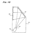
- Fig. 10 is a schematic view illustrating a structure of a conventional rear projection display device.
- the rear projection display device comprises an image projector (an optical engine) 102, a projection lens 103, a reflective mirror 104 and a transmissive diffusion screen 105 in a case 101.
- Image light projected from the image projector 102 is projected and magnified through the projection lens 103, reflected on the reflective mirror 104 and received on a rear surface of the translucent diffusion screen 105.
- An observer can watch the image in front of the diffusion screen 105.
- This type of the rear projection display device has an advantage in that upsizing of a screen is easily achieved in comparison with display devices using a direct view cathode-ray tube.
- the above-mentioned rear projection display device requires either using the projection lens 103 with a high magnification or extending an optical path between the image projector 102 and the screen 105.
- the projection lens has a limit to magnification under present circumstances.
- the case 101 increases its depth depending on the arrangement of the reflective mirror, leading to the difficulties in slimming.
- the case 101 increases its depth depending on the arrangement of the reflective mirror, leading the difficulties in slimming as well.
- JP 111458/1998 A discloses another conventional rear projection display device including an image forming system comprised of three reflective mirrors having curved surfaces.
- the image forming system comprises a first reflective mirror whose reflective surface is spherical and concave in shape, a second reflective mirror whose reflective surface is aspherical and convex in shape, and a third reflective mirror whose reflective surface is aspherical and convex in shape.
- Image light optically modulated in a liquid crystal panel is reflected on the first to third reflective mirrors in sequence and irradiated on the screen.
- the optical path is folded up by the first, second and third reflective mirrors, therefore the depth of the case can be reduced.
- image light should be emitted at an angle with respect to the screen, specifically; a main light beam of the image light should be emitted at an angle with respect to a normal to the screen.
- a main light beam of the image light should be emitted at an angle with respect to a normal to the screen.
- the mirror unit for forming and projecting image comprised of the first to third reflective mirrors is an optical part having a same function as that of a general projection lens. Considering efficiency of adjusting operations in assembling processes of the device, positioning accuracy of each mirror, and dust-resistance effect, it is preferable to shorten the distance between mirrors and integrally hold the mirrors in a holding body.
- Each of the first to third mirrors is placed in close to a front or rear side of the case.
- a holding system becomes big. Therefore it is difficult to hold the mirrors and place a dust-resistance mechanism by using the integral mechanism
- a rear projection display device comprising an image displaying liquid crystal panel of about 1 inch diagonally arranged in the optical engine, and magnifying and projecting an image onto a 50 inch diagonal screen
- the spacing between mirrors requires 20-30 cm with consideration given to the power arrangement of each mirror and image forming performance such as MTF. Therefore, it is difficult to integrally hold every mirror. Also another problem is found in assembling efficiency of the rear projection display device, positioning accuracy of the mirrors, and dust-resistance effect.
- one of the biggest problems of a reflective-type image forming optical system incorporating a reflective mirrors is interference between reflected light flux and members in the device.
- the light flux which travels from the first reflective mirror to the second reflective mirror passes in proximity to the upper part of the optical engine, which may cause interference between the light flux and the holding system for the image forming members. That places constraint on a design of the holding system and the mirror optical system.
- This invention was made to solve the above-mentioned problems and has an objective to reduce the depth of the display device.
- this invention has an objective to provide a rear projection display device capable of sending image light to a magnifying and projecting system without being cut off by the optical engine or the like.
- this invention has an objective to reduce the depth of the rear projection display device by projecting image light at an angle with respect to the screen without forming the first reflective mirror in an aspherical shape which is complicated to manufacture.
- This invention comprises an optical engine including an image forming unit for forming image information by spaciously modulating intensity of a light flux from a lightning unit including a light source, a first reflective mirror in a rotation-symmetric concave shape arranged opposite to the optical engine to receive the light flux from the optical engine, a second reflective mirror in a rotation-symmetric convex shape arranged opposite to the first reflective mirror, a third reflective mirror in a rotation-symmetric convex shape arranged opposite to the second reflective mirror, a fourth reflective mirror in a rotation-symmetric convex shape arranged opposite to the third reflective mirror, a plane reflective mirror arranged opposite to the fourth reflective mirror, and a screen on which an image from the plane reflective mirror is displayed.
- the second reflective mirror is in a position in proximity to an upper part of the optical engine and closer to the first reflective mirror than the optical engine is.
- the first, second, third reflective mirrors may be held in an integrated holding system.
- the described invention adopts four curved mirrors in all including the new curved reflective mirror arranged in proximity to the upper part of the optical engine, thereby preventing interference of the light flux reflected between reflective mirrors and the optical engine. Also the invention can improve assembling efficiency of the rear projection display device and positioning accuracy of the reflective mirrors and have dust-resistance effect by integrally holding the new reflective mirror arranged in proximity to the optical engine and other reflective mirrors around it in the holding system.
- the rear projection display device comprises an optical engine which optically modulates light emitted from a light source on the basis of image information and emits the modulated light, and projecting means for magnifying and projecting the emitted light from the optical engine at an angle to a rear surface of the screen.
- projecting means comprises an image forming system including a plurality of curved reflective mirrors and an auxiliary lens compensating the curved reflective mirrors for aberrations.
- an image light emitted from the optical unit is magnified and corrected for aberration by the projection means including the plurality of curved reflective mirrors and the auxiliary lens, and emitted at an angle to the screen.
- the invention is characterized by that the auxiliary lens is arranged between the optical unit and the first curved reflective mirror to which the light emitted from the optical unit is first irradiated.
- the auxiliary lens can be small because it is arranged between the optical unit and the first curved reflective mirror where the light flux passing through is the smallest.
- the image forming system of projecting means comprises a first curved reflective mirror having a concave surface opposite to the light flux from the optical unit, a second curved reflective mirror having a convex surface opposite to the light flux from the first curved reflective mirror, a third curved reflective mirror having a convex surface opposite to the light flux from the second curved reflective mirror and an auxiliary lens arranged on an optical path from the optical unit to the first curved reflective mirror.
- an image light emitted from the optical unit passes through the auxiliary lens, is reflected on the first curved reflective mirror, the second curved reflective mirror and the third curved reflective mirror in this order and is irradiated on the screen.
- the invention is characterized by comprising a first curved reflective mirror having a spherical reflective surface and an aspherical auxiliary lens.
- the spherical reflective surface of the first curved reflective mirror is formed with high accuracy as well as the auxiliary lens which compensates aspherical components.
- the reflective surface and the auxiliary lens can be accurately formed by a conventional polishing method, because the reflective surface of the curved reflective mirror is spherical in shape and the auxiliary lens is relatively small.
- the invention is characterized by that the second and third curved reflective mirrors have aspherical reflective surfaces.
- the second and third curved reflective mirror can be formed by a conventional polishing method, because they are big in comparison with the first curved reflective mirror and require moderate accuracy.
- Fig. 1 is a cross sectional view illustrating a schematic structure of a rear projection display device according to the present invention.
- Fig. 2 shows a schematic structure of an optical engine of the rear projection display device in Fig. 1.
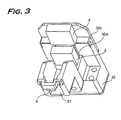
- Fig. 3 is a perspective view showing an example of a state where first, second, and third reflective mirrors were held in a holding member.
- Fig. 4 is a cross sectional view enlarging a screen structure of the rear projection display device in Fig. 1.
- a rear projection display device in the first embodiment comprises, as shown in Fig. 1, an optical engine 2 for generating image light, a screen 8 on which the image light is irradiated to form an image, a projection optical system for guiding the image light emitted from the optical engine 2 to the screen 8, and a case 1 for holding these components integrally.
- the projection optical system comprises first to fourth reflective mirrors 3, 4, 5, 6, which are aspherical reflective mirrors, have the functions of magnifying, projecting, and forming image, and are placed on a same axis, and a fifth reflective mirror 3, which is a flat reflective mirror and is placed perpendicular to an optical axis to fold up the image light.
- a feature of the first embodiment is that the functions of magnifying, projecting, and forming image are performed by an optimal disposition of power of three convex reflective mirrors and a spherical reflective mirror instead of two convex aspherical reflective mirrors and a concave aspherical reflective mirror.
- a reflective surface of the first reflective mirror 3 is spherical concave and arranged opposite to a part of the optical engine 2 from which an image light is emitted.
- the second reflective mirror 4 is aspherical convex and arranged opposite to the first reflective mirror 3 in the case 1.
- the third reflective mirror 5 is aspherical convex, like the second reflective mirror 4, and arranged opposite to the second reflective mirror 4 in the case 1.
- the fourth reflective mirror 6 is aspherical convex, like the third reflective mirror 5, and arranged between the third reflective mirror 5 and the screen 8.
- the fifth reflective mirror 7 is a flat plate and arranged above the third reflective mirror and parallel to the screen 8.
- the optical engine 2 is one of three-plate type optical engines and comprises a metal halide lamp 21 having a reflector 21a, a first dichroic mirror 22 selectively reflecting light in a wavelength band corresponding to red and transmitting light in other wavelength band, a second dichroic mirror 23 selectively reflecting light in a wavelength band corresponding to green and transmitting light in other wavelength band, first to third liquid crystal panels 27r, 27g, 27b optically modulating each color light separated on the first and second dichroic mirrors 22 and 23 on the basis of image information, and a dichroic prism 28 synthesizing each color light modulated on the first to third liquid crystal panels 27r, 27g, 27b.
- the white light emitted from the metal halide lamp 21 is reflected on the reflective mirror 21a. Then, ultra violet ray and infrared ray in the light are eliminated at an UV/IR filter (not shown), and the white light is irradiated to the first dichroic mirror 22 at an angle of 45° .
- the first dichroic mirror 22 selectively reflects light having red component (thereinafter it is referred to red light) in the irradiated white light.
- the reflected red light is reflected on the first reflective mirror 24 and then irradiated to the first liquid crystal panel 27r.
- the red light is incident to the dichroic prism 28 for color synthesis.
- the second dichroic mirror 23 selectively reflects light having green component (thereinafter it is referred to green light) in the irradiated colored light.
- the reflected green light is irradiated to the liquid crystal panel 27g.
- the green light is incident to the dichroic prism 28 for color synthesis.
- Blue light Light having blue component (thereinafter it is referred blue light) is transmitted through the second dichroic mirror 23, then is reflected on the second and third mirror 25 and 26 in sequence, and irradiated to the third liquid crystal panel 27b. After optically modulated on the third liquid crystal panel 27b on the basis of blue image information, the blue light is incident to the dichroic prism 28 for color synthesis.
- Each of color lights incident to the dichroic prism 28 is synthesized together to emit color image light.
- the image light emitted from the dichroic prism 28, as shown in Fig. 1, is emitted slantly up to right and irradiated to a first reflective mirror 3 in a spherical concave shape.
- the image light irradiated to the first reflective mirror 3 is reflected on the second to third reflective mirrors 4, 5, 6 in an aspherical convex shape in sequence and irradiated to the fifth reflective mirror 7 in a flat shape.
- the irradiated image light to the fifth reflective mirror 7 is corrected for an aberration such as astigmatism and a comatic aberration by the lens function of the first to fourth reflective mirrors 3 to 6, and is magnified at the same time.
- the image light reflected on the fifth reflective mirror 7 is irradiated on a back surface of the screen 8 to form an image thereon.
- the screen 7 includes a fresnel lens screen 81 formed with acrylic resin and a lenticular lens screen 82.
- a surface of the fresnel lens screen 81 on the incident side is flat, and a surface for emitting light is made with a plurality of protrusions in a loop shape.
- a surface of the lenticular lens screen 82 on the incident side is flat and a surface for emitting light is made with a plurality of protrusions in a semi-cylindrical shape.
- the fresnel lens 81 corrects the angle of the image light with its lens function and emits the image light.
- the image light emitted from the fresnel lens is irradiated to the back surface of the lenticular lens screen 82 to form an image thereon by the aid of the diffusing function of the lenticular lens screen 82.
- a light flux passing through between the first mirror and the second mirror may interfere the holding system for the image forming unit because the light flux passes in proximity to the upper part of the optical engine 2. This imposes restrictions in design regarding to the mechanism and the mirror optical system.
- the first embodiment resolves the above-mentioned problem by an optimal disposition of power of four reflective mirrors as keeping performance of the projection mirror unit.
- D/H 0.65 3.2 ⁇ f 123 /fa ⁇ 4.3 d1 + d2 ⁇
- f 123 synthetic focal length of the first, second, third reflective mirrors
- fa entire focal length (synthetic focal length of the first to fourth reflective mirrors)
- d1 distance between the first reflective mirror and the second reflective mirror
- d2 distance between the second reflective mirror and the third reflective mirror
- the projection mirror system can be thinner by satisfying the conditional expressions (1) and (2).
- the first, second, third reflective mirrors 3, 4, 5 can be arranged close to each other by satisfying the conditional expression (3), which allows the mirrors to be integrally held.
- three reflective mirrors 3, 4, 5 which are arranged closely to each other can be held by an integral holding system 30 as shown in Fig. 3.
- the first reflective mirror 3, the second reflective mirror 4, and the third reflective mirror 5 are fixed to the holding body 30.
- the holding body 30 has a window 31 through which a light flux from the optical engine 2 passes.
- a support section 30a is provided to install the first reflective mirror 3 in a rotation-symmetric convex shape at the position where is opposite to the window and light flax is introduced.
- a support section 30b is provided at a position where is opposite to the first reflective mirror 3 and on the upper part of the optical engine 2 to install the second reflective mirror 4 in a rotation-symmetric convex shape.
- a support section 30c is provided at a position where is opposite to the second reflective mirror 4 to install the third reflective mirror 5 in a rotation-symmetric convex shape.
- the reflective mirrors 3, 4, 5 are accurately installed to the holding body 30 by respectively fixing them to the support sections 30a, 30b, 30c of the holding body 30.
- the use of the holding body 30 has advantages to maintain assembling efficiency and positioning accuracy of mirrors.
- the reflected light from the first reflective mirror 3 is reflected again on the second reflective mirror 4 just before reaching the optical engine 2.
- a light flux which is supposed to pass over the optical engine 2 travels further upward, and a large amount of clearance for providing a mechanism above the optical engine 2 can be secured.
- an adjustment system for installing an image forming element or the like are provided on the optical engine 2, and such a system projects from the upper part of the optical engine 2 in many cases.
- the first embodiment has advantages in design of systems such as the adjustment system or the like and in design of reflective mirrors for controlling a light flux and preventing the light flux from interference.
- the mirrors basically should have an area large enough to reflect a light flux.
- the reflective mirrors should be circle rather than rectangular in consideration of processing cost of the mirrors.
- Fig. 5 is detailed data on the structure of the image forming system designed in accordance with this invention.
- fa is a focal length of the entire system.
- Each d1, d2, and d3 is the center-to-center liner distance between the first and the second reflective mirrors, the second and the third reflective mirrors, and the third and the fourth reflective mirrors.
- each surface number corresponds to the first to the fourth reflective mirrors respectively.
- K, A, B, C, and D respectively correspond to coefficients of expression 1 expressing the shape of the aspherical reflective mirror.
- the rear projection display device including the reflective-type image forming optical system can avoid interference between light flux reflected by the reflective mirrors and the optical engine. Holding integrally a reflective mirror in proximity to the optical engine and the other reflective mirrors around it allows to improve assembling efficiency and positioning accuracy of the reflective mirrors and to arrange the dust-resistance system.
- Fig. 6 is a cross sectional view showing a schematic structure of a rear projection display device according to a second embodiment of the present invention.
- a rear projection display device of the second embodiment comprises, as shown in Fig. 6, an optical engine 2 for generating image light, a screen 8 on which the image light is irradiated to form an image, a projection optical system for introducing the image light emitted from the optical engine 2 to the screen 8, and a case 1 for holding these components integrally.
- the projection optical system comprises first, second, third reflective mirrors 3a, 5a, 6a and an auxiliary lens 9.
- a reflective surface of the first reflective mirror 3a is spherical concave and arranged opposite to a part of the optical engine 2 from which an image light is emitted.
- the second reflective mirror 5a (corresponding to the third reflective mirror 5 in the first embodiment) is aspherical convex and arranged opposite to the first reflective mirror 3a in the case 1.
- the third reflective mirror 6a (corresponding to the fourth reflective mirror 6 in the first embodiment) is aspherical convex, like the second reflective mirror 5a, and arranged between the first reflective mirror 3a and the screen 8 in the case 1.
- the fourth reflective mirror 7 (corresponding to the fifth reflective mirror 7 in the first embodiment) is a flat plate and arranged above the second reflective mirror 5a and parallel to the screen 8.
- the optical engine 2 as described in the first embodiment and shown in Fig.2, is one of three-chips types.
- Image light emitted from a dichroic prism 28, as shown in Fig. 6, is emitted slantly up to left, passes through the aspherical auxiliary lens 9 and is irradiated to the reflective mirror 3a in a spherical concave shape.
- the image light irradiated to the first reflective mirror 3a is reflected on the second and the third reflective mirrors 5a, 6a in aspherical convex shapes in this order and irradiated to the fourth reflective mirror 7 of a flat plate.
- the irradiated image light to the fourth reflective mirror 7 is corrected for an aberration such as astigmatism and a comatic aberration by the optical power depending on shapes of the first, second, third reflective mirrors 3a, 5a, 6a and the auxiliary lens 9, and is magnified at the same time.
- the first, second, third reflective mirrors 3a, 5a, 6a and the auxiliary lens 9 is so designed as to build an optical structure as shown in Fig. 7.
- the image light reflected on the fourth reflective mirror 7 is irradiated to the back surface of the screen 8 to form an image.
- the angle of the image light is corrected by the lens function and emitted.
- the image light emitted from the fresnel lens is irradiated to the back surface of a lenticular lens screen 82 to form an image by the aid of the diffusing function.
- the auxiliary lens 9 according to the second embodiment comprises aspherical components required of the first reflective mirror 3a which should have the most accurate surface. Therefore, it is possible to form the well-accurate first reflective mirror 3a by polishing.
- the light flux is magnified in sequence after being emitted from the optical engine 2.
- the auxiliary lens 9 is arranged between the optical engine 2 and the first reflective mirror 3a where relatively thin light flux passes through, therefore, the auxiliary lens 9 can be made small with high-accuracy by polishing.
- the first reflective mirror 3a of a spherical concave shape, the auxiliary lens 9 of an aspherical shape for compensating the first mirror, and the second and third reflective mirrors of aspherical convex shapes 5a, 6a are used as members of the projection optical system, the system is not limited to the members and may use three or more curved reflective mirrors.
- the auxiliary lens 9 is arranged between the optical engine 2 and the first reflective mirror 3a to compensate the aspherical component of the first reflective mirror 3a
- the auxiliary lens 9 may be arranged either between the first reflective mirror 3a and the second reflective mirror 5a or both.
- the auxiliary lens comprises aspherical components required of the curved reflective mirror which should have the highly accurate surface, thus it is possible to form the well-accurate curved reflective mirror by polishing, resulting in improvement of reliability of the device.
- FIG. 8 is a schematic cross sectional view showing a rear projection display device with a 50-inch diagonal screen which applies the invention of the first embodiment.
- Fig. 9 is a schematic cross sectional view showing a rear projection display device with a 50-inch diagonal screen and an optical engine comprising lenses. As shown in Fig.
- image light which is emitted from an optical engine 2a comprising lenses to perform magnification, projection, and image formation instead of the first to third reflective lenses 3, 4, 5 is reflected on a flat reflective mirror 2b and a fourth reflective mirror 6 of an aspherical convex shape, then irradiated to the fifth reflective mirror 7 of a flat plate.
- the image light reflected on the fifth reflective mirror 7 is irradiated to the back surface of the screen 8 to form image.
- the depth of the rear projection display device in Fig. 8 is 30 mm
- its height needs 1400 mm.
- the depth of the rear projection display device in Fig. 9 its height needs 1600 mm.
- the rear projection display device applying the invention of the first embodiment which comprises four reflective mirrors can be smaller.
- this invention is suitably applicable to a slim display device which receives a projected image from an image projection device (an optical engine) on a back surface of a screen and emits the image light toward an observer positioned in front of the screen, for example, a large and slim display device and a large and slim television device.
- an image projection device an optical engine
Landscapes
- Physics & Mathematics (AREA)
- Engineering & Computer Science (AREA)
- Multimedia (AREA)
- Signal Processing (AREA)
- General Physics & Mathematics (AREA)
- Optics & Photonics (AREA)
- Projection Apparatus (AREA)
- Lenses (AREA)
- Overhead Projectors And Projection Screens (AREA)
- Devices For Indicating Variable Information By Combining Individual Elements (AREA)
Abstract
Description
H = height of the screen
f123 = synthetic focal length of the first, second, third reflective mirrors
fa = entire focal length (synthetic focal length of the first to fourth reflective mirrors)
d1 = distance between the first reflective mirror and the second reflective mirror
d2 = distance between the second reflective mirror and the third reflective mirror
Claims (7)
- A rear projection display device comprising:an optical engine comprising an image forming unit for forming image information by spaciously modulating intensity of light flux from a lighting unit including a light source;a first reflective mirror in a rotation-symmetric concave shape arranged opposite to the optical engine to receive the light flux from the optical engine;a second reflective mirror in a rotation-symmetric convex shape arranged opposite to the first reflective mirror;a third reflective mirror in a rotation-symmetric convex shape arranged opposite to the second reflective mirror;a fourth reflective mirror in a rotation-symmetric convex shape arranged opposite to the third reflective mirror;a plane reflective mirror arranged opposite to the fourth reflective mirror; anda screen on which an image from the plane reflective mirror is displayed, whereinthe second reflective mirror is in a position in proximity to an upper part of the optical engine and closer to the first reflective mirror than the optical engine is.
- The rear projection display device in claim 1, wherein
the first, second, third reflective mirrors are held integrally in an integrated holding system. - A rear projection display device comprising:an optical engine which optically modulates light emitted from a light source on the basis of image information and emits the modulated light; andprojecting means for magnifying and projecting the image light from the optical engine at an angle to a back surface of a screen, andthe image is observed from a front surface of the screen; whereinthe projecting means comprises an image forming system including a plurality of curved reflective mirrors and an auxiliary lens compensating the curved reflective mirrors for aberrations.
- The rear projection display device according to claim 3, wherein
the auxiliary lens is arranged between the optical unit and the first curved reflective mirror to which the light emitted from the optical unit is first irradiated. - The rear projection display device according to claim 3, wherein
the image forming system of the projecting means comprises a first curved reflective mirror having a concave surface opposite to the light flux from the optical unit, a second curved reflective mirror having a convex surface opposite to the light flux from the first curved reflective mirror, a third curved reflective mirror having a convex surface opposite to the light flux from the second curved reflective mirror and an auxiliary lens arranged on an optical path from the optical unit to the first curved reflective mirror. - The rear projection display device according either of claim 4 or 5, wherein
the first curved reflective mirror has a spherical reflective surface and the auxiliary lens is aspherical. - The rear projection display device according to claim 4, wherein
the second and third curved reflective mirrors have aspherical reflective surfaces.
Applications Claiming Priority (5)
| Application Number | Priority Date | Filing Date | Title |
|---|---|---|---|
| JP22125199 | 1999-08-04 | ||
| JP22125199 | 1999-08-04 | ||
| JP2000096563 | 2000-03-31 | ||
| JP2000096563 | 2000-03-31 | ||
| PCT/JP2000/005277 WO2001011425A1 (en) | 1999-08-04 | 2000-08-04 | Rear surface projection type display device |
Publications (2)
| Publication Number | Publication Date |
|---|---|
| EP1205791A1 true EP1205791A1 (en) | 2002-05-15 |
| EP1205791A4 EP1205791A4 (en) | 2006-09-13 |
Family
ID=26524185
Family Applications (1)
| Application Number | Title | Priority Date | Filing Date |
|---|---|---|---|
| EP00951892A Withdrawn EP1205791A4 (en) | 1999-08-04 | 2000-08-04 | Rear surface projection type display device |
Country Status (8)
| Country | Link |
|---|---|
| US (1) | US6752500B1 (en) |
| EP (1) | EP1205791A4 (en) |
| JP (1) | JP4063538B2 (en) |
| KR (1) | KR100726921B1 (en) |
| CN (1) | CN1178102C (en) |
| CA (1) | CA2381093C (en) |
| TW (1) | TW436662B (en) |
| WO (1) | WO2001011425A1 (en) |
Cited By (15)
| Publication number | Priority date | Publication date | Assignee | Title |
|---|---|---|---|---|
| WO2002100114A1 (en) * | 2001-06-07 | 2002-12-12 | Carl Zeiss Jena Gmbh | Array for projecting a polychromatic image on a projection surface |
| WO2003107663A1 (en) * | 2002-06-12 | 2003-12-24 | Silicon Optix Inc. | Short throw projection system and method |
| FR2856156A1 (en) * | 2003-06-11 | 2004-12-17 | Thomson Licensing Sa | Projection lens for retroprojection apparatus, has auxiliary lenses that emit diverging light beam towards plane screen, and hyperbolic mirror that is oriented such that it receives light from lenses on its convex surface |
| WO2004111699A1 (en) * | 2003-06-11 | 2004-12-23 | Thomson Licensing | Objective for a projection or backprojection apparatus |
| EP1646231A1 (en) * | 2004-10-05 | 2006-04-12 | Samsung Electronics Co, Ltd | Image projector |
| EP1652378A4 (en) * | 2004-05-11 | 2006-07-12 | Samsung Electronics Co Ltd | IMAGE TRAINING APPARATUS AND PROJECTION TELEVISION STATION HAVING THE APPARATUS |
| EP1681862A1 (en) * | 2005-01-14 | 2006-07-19 | Inshon Inc. | Optic projecting method and structure of rear projection TV for dual projecting system |
| EP1712953A1 (en) * | 2005-04-11 | 2006-10-18 | NEC Viewtechnology, Ltd. | Projection display apparatus |
| KR100811178B1 (en) | 2006-05-26 | 2008-03-07 | 삼성전자주식회사 | Image projection device |
| US7384158B2 (en) | 2003-01-08 | 2008-06-10 | Silicon Optix Inc | Image projection system and method |
| EP1939663A1 (en) * | 2006-12-29 | 2008-07-02 | Thomson Licensing | Projection display with an aspheric mirror |
| EP1745647A4 (en) * | 2004-05-14 | 2009-02-25 | Samsung Electronics Co Ltd | IMAGE FORMING APPARATUS HAVING A TWO-STAGE STRUCTURE AND TELEPROJECTOR PROVIDED WITH SAID APPARATUS |
| GB2463733A (en) * | 2008-09-29 | 2010-03-31 | Meistream Internat Optical Ltd | Wide angle projection lens module |
| US7714943B2 (en) | 2002-06-12 | 2010-05-11 | Geo Semiconductor Inc. | Ultra-thin image projection system |
| US7738190B2 (en) | 2008-09-27 | 2010-06-15 | Meistream International Optical Ltd. | Optical engine and wide angle projection lens module thereof |
Families Citing this family (49)
| Publication number | Priority date | Publication date | Assignee | Title |
|---|---|---|---|---|
| JP2003161885A (en) | 2001-11-29 | 2003-06-06 | Minolta Co Ltd | Oblique projection optical system |
| JP2003149744A (en) | 2001-11-09 | 2003-05-21 | Mitsubishi Electric Corp | Image display system |
| JP2004012749A (en) * | 2002-06-06 | 2004-01-15 | Canon Inc | Projector device |
| US20070165192A1 (en) * | 2006-01-13 | 2007-07-19 | Silicon Optix Inc. | Reduced field angle projection display system |
| US6984044B2 (en) * | 2002-07-30 | 2006-01-10 | Canon Kabushiki Kaisha | Projection optical system, projection type image display apparatus, and image display system |
| US7150537B2 (en) | 2002-08-16 | 2006-12-19 | Infocus Corporation | Projection television device and screen |
| US7175287B2 (en) * | 2002-08-16 | 2007-02-13 | Infocus Corporation | Wide angle projection lens |
| US7009765B2 (en) * | 2002-08-16 | 2006-03-07 | Infocus Corporation | Wide angle lens system having a distorted intermediate image |
| US7102820B2 (en) * | 2002-08-16 | 2006-09-05 | Infocus Corporation | Flat valley fresnel lens for a display device |
| US7341353B2 (en) * | 2002-08-16 | 2008-03-11 | Infocus Corporation | Variable fresnel screen for use in projection device |
| US6896375B2 (en) * | 2002-08-16 | 2005-05-24 | Infocus Corporation | Rear projection display device having multiple mirrors that are substantially parallel to a screen |
| KR20040020330A (en) * | 2002-08-30 | 2004-03-09 | 엘지전자 주식회사 | Projection system |
| JP2004271726A (en) * | 2003-03-06 | 2004-09-30 | Seiko Epson Corp | Rear projection display device |
| JP4123025B2 (en) * | 2003-03-28 | 2008-07-23 | コニカミノルタオプト株式会社 | Oblique projection optical system and image projection apparatus |
| TWM245695U (en) * | 2003-07-14 | 2004-10-01 | Coretronic Corp | Rear projection display apparatus |
| US7080910B2 (en) * | 2003-08-19 | 2006-07-25 | Infocus Corporation | Method and system for a thermal architecture and user adjustable keystone in a display device |
| US7259912B2 (en) | 2004-01-06 | 2007-08-21 | Infocus Corporation | Fresnel lens having reduced distortions |
| EP1745329B1 (en) * | 2004-03-30 | 2016-05-04 | Thomson Licensing | Projection module and projector incorporating same |
| US7055969B2 (en) * | 2004-04-29 | 2006-06-06 | Hewlett-Packard Development Company, L.P. | Reflective optical assembly |
| JP2006099071A (en) * | 2004-09-01 | 2006-04-13 | Konica Minolta Opto Inc | Image projecting apparatus |
| JP2006138882A (en) * | 2004-11-10 | 2006-06-01 | Konica Minolta Opto Inc | Oblique projection optical system |
| JP2006178406A (en) | 2004-11-25 | 2006-07-06 | Konica Minolta Opto Inc | Projection optical system |
| JP2006208553A (en) * | 2005-01-26 | 2006-08-10 | Tohoku Univ | Rear projection display optical system with limited projector light emission angle |
| US20060221309A1 (en) * | 2005-04-01 | 2006-10-05 | Konica Minolta Opto, Inc. | Projection type of image displaying apparatus |
| JP2006285044A (en) * | 2005-04-01 | 2006-10-19 | Konica Minolta Opto Inc | Projection-type image display apparatus |
| KR20060117072A (en) * | 2005-05-12 | 2006-11-16 | 삼성전기주식회사 | Back projection type display device using diffractive optical modulator |
| JP2006322981A (en) * | 2005-05-17 | 2006-11-30 | Konica Minolta Opto Inc | Projection optical system unit and projection type image display device using the same |
| KR20060131081A (en) * | 2005-06-15 | 2006-12-20 | 삼성전자주식회사 | Removable rear projection unit for the projector |
| JP4655813B2 (en) | 2005-08-09 | 2011-03-23 | 株式会社日立製作所 | Reflector and projection-type image display device using the same |
| US8092329B2 (en) | 2005-08-31 | 2012-01-10 | Wick Werks, LLC | Bicycle chain rings with ramps |
| US20070085980A1 (en) * | 2005-10-18 | 2007-04-19 | Scott Lerner | Projection assembly |
| US7611250B2 (en) * | 2005-10-27 | 2009-11-03 | Chunghwa Picture Tubes, Ltd. | Projector |
| JP2007212517A (en) * | 2006-02-07 | 2007-08-23 | Konica Minolta Opto Inc | Image projector |
| JP4584160B2 (en) * | 2006-03-01 | 2010-11-17 | Necディスプレイソリューションズ株式会社 | Projection display |
| US7660037B2 (en) | 2006-06-06 | 2010-02-09 | Seiko Epson Corporation | Screen, projector, and image display device |
| DE102007006094B4 (en) * | 2007-02-07 | 2017-06-01 | Young Optics Inc. | Rear projection device and method for a rear projection device |
| JP5166847B2 (en) * | 2007-12-14 | 2013-03-21 | 三洋電機株式会社 | Projection display device |
| TW200931155A (en) * | 2008-01-02 | 2009-07-16 | Young Optics Inc | Display device and design method thereof |
| WO2009117351A2 (en) * | 2008-03-19 | 2009-09-24 | Mezmeriz, Inc. | Micro electro-mechanical system (mems) based high definition micro-projectors |
| JP5202167B2 (en) * | 2008-08-01 | 2013-06-05 | 三菱電機株式会社 | Projection-type image display device |
| TW201033637A (en) * | 2009-03-12 | 2010-09-16 | Young Optics Inc | Fixed-focus lens and apparatus integrating optical projection and image detection |
| DE102010010328A1 (en) * | 2010-03-04 | 2011-09-29 | Jos. Schneider Optische Werke Gmbh | Planar imaging system |
| WO2012132294A1 (en) * | 2011-03-28 | 2012-10-04 | 富士フイルム株式会社 | Projection optical system and projection display device |
| JP5727591B2 (en) * | 2011-03-28 | 2015-06-03 | 富士フイルム株式会社 | Projection optical system and projection display device |
| CN107295283B (en) * | 2016-03-30 | 2024-03-08 | 芋头科技(杭州)有限公司 | Display system of robot |
| KR102479811B1 (en) | 2016-06-13 | 2022-12-23 | 삼성전자주식회사 | Air conditioner and control method thereof |
| CN107015427A (en) * | 2017-02-24 | 2017-08-04 | 联想(北京)有限公司 | Projection arrangement and electronic equipment |
| DE202018106156U1 (en) | 2018-10-26 | 2018-11-08 | E-Lead Electronic Co., Ltd. | Embedded head-up display device |
| CN113031238A (en) * | 2021-04-14 | 2021-06-25 | 中国科学院长春光学精密机械与物理研究所 | Multi-mirror integrated large-view-field long-focus off-axis four-mirror optical system |
Family Cites Families (13)
| Publication number | Priority date | Publication date | Assignee | Title |
|---|---|---|---|---|
| JPS5251538Y2 (en) * | 1972-04-25 | 1977-11-22 | ||
| JP2786796B2 (en) * | 1993-06-23 | 1998-08-13 | シャープ株式会社 | projector |
| US5410434A (en) * | 1993-09-09 | 1995-04-25 | Ultratech Stepper, Inc. | Reflective projection system comprising four spherical mirrors |
| JPH07109820B2 (en) * | 1994-03-14 | 1995-11-22 | キヤノン株式会社 | Circuit manufacturing method and exposure apparatus |
| WO1997001787A1 (en) | 1995-06-26 | 1997-01-16 | Nissho Giken Kabushiki Kaisha | Projection display |
| JPH09138349A (en) * | 1995-09-11 | 1997-05-27 | Semiconductor Energy Lab Co Ltd | Display device |
| US5677788A (en) | 1996-03-28 | 1997-10-14 | Hughes Electronics | Two-stage projection system |
| JPH10111458A (en) | 1996-10-03 | 1998-04-28 | Nissho Giken Kk | Reflective imaging optics |
| FR2764081B1 (en) * | 1997-06-03 | 1999-08-20 | Reosc | WIDE ANGLE CATOPTRIC SYSTEM WITH MIRRORS |
| US6002826A (en) * | 1998-08-28 | 1999-12-14 | Brookhaven Science Associates | Thin display optical projector |
| US6561649B1 (en) * | 1999-07-09 | 2003-05-13 | Sarnoff Corporation | Compact rear projection system using birefringent optics |
| JP3808293B2 (en) * | 2000-07-28 | 2006-08-09 | Necビューテクノロジー株式会社 | Reflective imaging optical system |
| JP3538128B2 (en) * | 2000-08-08 | 2004-06-14 | Necビューテクノロジー株式会社 | Projection device |
-
2000
- 2000-08-04 JP JP2001516020A patent/JP4063538B2/en not_active Expired - Fee Related
- 2000-08-04 KR KR1020027001512A patent/KR100726921B1/en not_active Expired - Fee Related
- 2000-08-04 CN CNB008137536A patent/CN1178102C/en not_active Expired - Fee Related
- 2000-08-04 CA CA002381093A patent/CA2381093C/en not_active Expired - Fee Related
- 2000-08-04 US US10/048,449 patent/US6752500B1/en not_active Expired - Fee Related
- 2000-08-04 WO PCT/JP2000/005277 patent/WO2001011425A1/en not_active Ceased
- 2000-08-04 EP EP00951892A patent/EP1205791A4/en not_active Withdrawn
- 2000-08-04 TW TW089115892A patent/TW436662B/en not_active IP Right Cessation
Cited By (22)
| Publication number | Priority date | Publication date | Assignee | Title |
|---|---|---|---|---|
| US6817719B2 (en) | 2001-06-07 | 2004-11-16 | Carl Zeiss Jena Gmbh | Array for projecting a polyciiromatic image on a projection surface |
| WO2002100114A1 (en) * | 2001-06-07 | 2002-12-12 | Carl Zeiss Jena Gmbh | Array for projecting a polychromatic image on a projection surface |
| WO2003107663A1 (en) * | 2002-06-12 | 2003-12-24 | Silicon Optix Inc. | Short throw projection system and method |
| US7714943B2 (en) | 2002-06-12 | 2010-05-11 | Geo Semiconductor Inc. | Ultra-thin image projection system |
| US7239360B2 (en) | 2002-06-12 | 2007-07-03 | Silicon Optix Inc. | Short throw projection system and method |
| US7384158B2 (en) | 2003-01-08 | 2008-06-10 | Silicon Optix Inc | Image projection system and method |
| CN100409062C (en) * | 2003-06-11 | 2008-08-06 | 汤姆森特许公司 | Objective lens for projection device or rear projection device |
| FR2856156A1 (en) * | 2003-06-11 | 2004-12-17 | Thomson Licensing Sa | Projection lens for retroprojection apparatus, has auxiliary lenses that emit diverging light beam towards plane screen, and hyperbolic mirror that is oriented such that it receives light from lenses on its convex surface |
| WO2004111699A1 (en) * | 2003-06-11 | 2004-12-23 | Thomson Licensing | Objective for a projection or backprojection apparatus |
| US7488077B2 (en) | 2003-06-11 | 2009-02-10 | Thomson Licensing | Objective for a projection apparatus, and corresponding front-projection or backprojection apparatus |
| EP1652378A4 (en) * | 2004-05-11 | 2006-07-12 | Samsung Electronics Co Ltd | IMAGE TRAINING APPARATUS AND PROJECTION TELEVISION STATION HAVING THE APPARATUS |
| EP1745647A4 (en) * | 2004-05-14 | 2009-02-25 | Samsung Electronics Co Ltd | IMAGE FORMING APPARATUS HAVING A TWO-STAGE STRUCTURE AND TELEPROJECTOR PROVIDED WITH SAID APPARATUS |
| EP1646231A1 (en) * | 2004-10-05 | 2006-04-12 | Samsung Electronics Co, Ltd | Image projector |
| EP1681862A1 (en) * | 2005-01-14 | 2006-07-19 | Inshon Inc. | Optic projecting method and structure of rear projection TV for dual projecting system |
| EP1712953A1 (en) * | 2005-04-11 | 2006-10-18 | NEC Viewtechnology, Ltd. | Projection display apparatus |
| US7717573B2 (en) | 2005-04-11 | 2010-05-18 | Nec Viewtechnology, Ltd. | Projection display apparatus |
| KR100811178B1 (en) | 2006-05-26 | 2008-03-07 | 삼성전자주식회사 | Image projection device |
| WO2008082476A1 (en) * | 2006-12-29 | 2008-07-10 | Thomson Licensing | Aspheric mirror for a projection display |
| EP1939663A1 (en) * | 2006-12-29 | 2008-07-02 | Thomson Licensing | Projection display with an aspheric mirror |
| US7738190B2 (en) | 2008-09-27 | 2010-06-15 | Meistream International Optical Ltd. | Optical engine and wide angle projection lens module thereof |
| GB2463733A (en) * | 2008-09-29 | 2010-03-31 | Meistream Internat Optical Ltd | Wide angle projection lens module |
| GB2463733B (en) * | 2008-09-29 | 2010-10-13 | Meistream Internat Optical Ltd | Wide angle projection lens module |
Also Published As
| Publication number | Publication date |
|---|---|
| JP4063538B2 (en) | 2008-03-19 |
| US6752500B1 (en) | 2004-06-22 |
| CA2381093A1 (en) | 2001-02-15 |
| CN1178102C (en) | 2004-12-01 |
| KR20020021807A (en) | 2002-03-22 |
| CN1377476A (en) | 2002-10-30 |
| KR100726921B1 (en) | 2007-06-14 |
| TW436662B (en) | 2001-05-28 |
| EP1205791A4 (en) | 2006-09-13 |
| WO2001011425A1 (en) | 2001-02-15 |
| CA2381093C (en) | 2008-02-05 |
Similar Documents
| Publication | Publication Date | Title |
|---|---|---|
| US6752500B1 (en) | Rear surface projection type display device | |
| JPWO2001011425A1 (en) | rear projection display device | |
| CN110832377B (en) | Image display device and projection optical system | |
| US7984994B2 (en) | Image display apparatus | |
| US8087789B2 (en) | Projection optical system and projection display device | |
| JP3538128B2 (en) | Projection device | |
| EP3415974A1 (en) | Display device and head-up display | |
| US12222636B2 (en) | Projection lens and projection device | |
| EP3677947A1 (en) | Headup display device | |
| JP5544711B2 (en) | projector | |
| JP3702890B2 (en) | Optical assembly and projector | |
| US6631039B2 (en) | Optical unit and projector using the same | |
| US20100103380A1 (en) | Critical abbe illumination configuration | |
| US20070252956A1 (en) | Projection type display apparatus | |
| CN115145014B (en) | Affiliated optical systems and projection display systems | |
| US8052290B2 (en) | Rear-projection-type display apparatus | |
| CN101160548A (en) | image display device | |
| JP2008102536A (en) | Rear surface projection type display device | |
| US7157688B2 (en) | Projection system and optical path transfer device thereof | |
| US12181788B2 (en) | Projection lens with a first optical system to form an intermediate image of an optical image and projection device | |
| US20210333700A1 (en) | Projection optical apparatus and projector | |
| JP2007025652A (en) | Image display device | |
| CN115145013B (en) | Auxiliary optical system and projection display system | |
| WO2024080170A1 (en) | Optical system and virtual image display device | |
| JP2022036752A (en) | Lens unit and image projection device |
Legal Events
| Date | Code | Title | Description |
|---|---|---|---|
| PUAI | Public reference made under article 153(3) epc to a published international application that has entered the european phase |
Free format text: ORIGINAL CODE: 0009012 |
|
| 17P | Request for examination filed |
Effective date: 20020228 |
|
| AK | Designated contracting states |
Kind code of ref document: A1 Designated state(s): DE FR GB |
|
| RIC1 | Information provided on ipc code assigned before grant |
Ipc: G09F 9/00 20060101ALI20060531BHEP Ipc: H04N 5/74 20060101AFI20060531BHEP Ipc: G03B 21/10 20060101ALI20060531BHEP Ipc: G02B 17/00 20060101ALI20060531BHEP Ipc: G02B 17/06 20060101ALI20060531BHEP |
|
| A4 | Supplementary search report drawn up and despatched |
Effective date: 20060817 |
|
| 17Q | First examination report despatched |
Effective date: 20080109 |
|
| STAA | Information on the status of an ep patent application or granted ep patent |
Free format text: STATUS: THE APPLICATION HAS BEEN WITHDRAWN |
|
| 18W | Application withdrawn |
Effective date: 20090730 |