EP1205640A2 - Combined system for cooling by water injection and washing of a gas turbine compressor - Google Patents
Combined system for cooling by water injection and washing of a gas turbine compressor Download PDFInfo
- Publication number
- EP1205640A2 EP1205640A2 EP01309250A EP01309250A EP1205640A2 EP 1205640 A2 EP1205640 A2 EP 1205640A2 EP 01309250 A EP01309250 A EP 01309250A EP 01309250 A EP01309250 A EP 01309250A EP 1205640 A2 EP1205640 A2 EP 1205640A2
- Authority
- EP
- European Patent Office
- Prior art keywords
- compressor
- nozzles
- dual function
- droplets
- manifolds
- Prior art date
- Legal status (The legal status is an assumption and is not a legal conclusion. Google has not performed a legal analysis and makes no representation as to the accuracy of the status listed.)
- Granted
Links
Images


Classifications
-
- F—MECHANICAL ENGINEERING; LIGHTING; HEATING; WEAPONS; BLASTING
- F02—COMBUSTION ENGINES; HOT-GAS OR COMBUSTION-PRODUCT ENGINE PLANTS
- F02C—GAS-TURBINE PLANTS; AIR INTAKES FOR JET-PROPULSION PLANTS; CONTROLLING FUEL SUPPLY IN AIR-BREATHING JET-PROPULSION PLANTS
- F02C7/00—Features, components parts, details or accessories, not provided for in, or of interest apart form groups F02C1/00 - F02C6/00; Air intakes for jet-propulsion plants
- F02C7/12—Cooling of plants
- F02C7/14—Cooling of plants of fluids in the plant, e.g. lubricant or fuel
-
- F—MECHANICAL ENGINEERING; LIGHTING; HEATING; WEAPONS; BLASTING
- F02—COMBUSTION ENGINES; HOT-GAS OR COMBUSTION-PRODUCT ENGINE PLANTS
- F02C—GAS-TURBINE PLANTS; AIR INTAKES FOR JET-PROPULSION PLANTS; CONTROLLING FUEL SUPPLY IN AIR-BREATHING JET-PROPULSION PLANTS
- F02C7/00—Features, components parts, details or accessories, not provided for in, or of interest apart form groups F02C1/00 - F02C6/00; Air intakes for jet-propulsion plants
- F02C7/12—Cooling of plants
- F02C7/14—Cooling of plants of fluids in the plant, e.g. lubricant or fuel
- F02C7/141—Cooling of plants of fluids in the plant, e.g. lubricant or fuel of working fluid
- F02C7/143—Cooling of plants of fluids in the plant, e.g. lubricant or fuel of working fluid before or between the compressor stages
- F02C7/1435—Cooling of plants of fluids in the plant, e.g. lubricant or fuel of working fluid before or between the compressor stages by water injection
-
- B—PERFORMING OPERATIONS; TRANSPORTING
- B05—SPRAYING OR ATOMISING IN GENERAL; APPLYING FLUENT MATERIALS TO SURFACES, IN GENERAL
- B05B—SPRAYING APPARATUS; ATOMISING APPARATUS; NOZZLES
- B05B7/00—Spraying apparatus for discharge of liquids or other fluent materials from two or more sources, e.g. of liquid and air, of powder and gas
- B05B7/02—Spray pistols; Apparatus for discharge
- B05B7/04—Spray pistols; Apparatus for discharge with arrangements for mixing liquids or other fluent materials before discharge
- B05B7/0416—Spray pistols; Apparatus for discharge with arrangements for mixing liquids or other fluent materials before discharge with arrangements for mixing one gas and one liquid
- B05B7/0441—Spray pistols; Apparatus for discharge with arrangements for mixing liquids or other fluent materials before discharge with arrangements for mixing one gas and one liquid with one inner conduit of liquid surrounded by an external conduit of gas upstream the mixing chamber
-
- B—PERFORMING OPERATIONS; TRANSPORTING
- B05—SPRAYING OR ATOMISING IN GENERAL; APPLYING FLUENT MATERIALS TO SURFACES, IN GENERAL
- B05B—SPRAYING APPARATUS; ATOMISING APPARATUS; NOZZLES
- B05B9/00—Spraying apparatus for discharge of liquids or other fluent material, without essentially mixing with gas or vapour
- B05B9/01—Spray pistols, discharge devices
-
- F—MECHANICAL ENGINEERING; LIGHTING; HEATING; WEAPONS; BLASTING
- F01—MACHINES OR ENGINES IN GENERAL; ENGINE PLANTS IN GENERAL; STEAM ENGINES
- F01D—NON-POSITIVE DISPLACEMENT MACHINES OR ENGINES, e.g. STEAM TURBINES
- F01D25/00—Component parts, details, or accessories, not provided for in, or of interest apart from, other groups
- F01D25/002—Cleaning of turbomachines
-
- F—MECHANICAL ENGINEERING; LIGHTING; HEATING; WEAPONS; BLASTING
- F04—POSITIVE - DISPLACEMENT MACHINES FOR LIQUIDS; PUMPS FOR LIQUIDS OR ELASTIC FLUIDS
- F04D—NON-POSITIVE-DISPLACEMENT PUMPS
- F04D29/00—Details, component parts, or accessories
- F04D29/70—Suction grids; Strainers; Dust separation; Cleaning
- F04D29/701—Suction grids; Strainers; Dust separation; Cleaning especially adapted for elastic fluid pumps
- F04D29/705—Adding liquids
Definitions
- This invention relates to turbo machinery and, more particularly, to a combined water-wash and wet-compression system for the compressor of a gas turbine.
- the compressor of a gas turbine requires periodic cleaning (sometimes referred to as water wash).
- One method of cleaning includes spraying droplets of cleanser into the inlet of the compressor. When this procedure is performed while the compressor is in operation, demineralized water is used and the droplets are sized to be large enough so that the drag forces are dominated by the inertia forces that tend to cause the droplets to impinge on the hardware of the compressor and provide the cleaning action.
- intercooling includes spraying droplets of coolant into the inlet of the compressor.
- wet compression When the mixture of gas and water is compressed (generally referred to as wet compression), the temperature of the gas increases and provides the driving potential for evaporation. The evaporation of water cools the gas, and so acts as an intercooler.
- coolant droplets are sized to be small enough so that the inertia forces are dominated by the drag forces that tend to cause the droplets to flow past the hardware of the compressor and travel into subsequent stages of the compressor where the droplets evaporate and provide the desired intercooling.
- the current practice is to use separate systems for water washing and wet compression, each having their own set of controls and hardware.
- This invention relates to a device or system that will provide a stream of large droplets for water wash that will impinge on the hardware of the compressor and provide the required cleaning of the compressor, as well as a stream of small droplets for wet compression that will not impinge on the hardware of the compressor, but will flow into the downstream stages of the compressor where the droplets will evaporate to provide intercooling.
- water droplets for both water wash and wet compression are supplied by dual-function nozzles within a single system.
- the nozzles may be of a commercially available twin-fluid type where a sheet of liquid is disturbed by a high-velocity sheet of air so as to eventually cause the sheet to disintegrate into ligaments and then into small drops when in the atomization mode.
- a sheet of liquid is disturbed by a high-velocity sheet of air so as to eventually cause the sheet to disintegrate into ligaments and then into small drops when in the atomization mode.
- the flow of atomizing air is halted, and the liquid sheet is simply broken up by ambient air into large droplets suitable for water wash.
- Electro-mechanical atomizers are a family of atomizers that includes pressure atomizers, rotary atomizers, electrostatic atomizers, ultrasonic atomizers, vibrating-capillary atomizers, windmill atomizers and flashing atomizers, for example.
- This family of atomizers produces small droplets when the pressure of the liquid is increased, when an electric field is applied, when gas is dissolved, or when some component of the nozzle is set into motion.
- An ultrasonic atomizer utilizing piezoelectric discs is described herein.
- the piezoelectric discs produce cyclic contraction and expansion that results in a pressure wave that travels axially along the nozzle, interacting with the liquid in the nozzle to cause a mist of small droplets to be ejected from the nozzle.
- the liquid droplets return to the larger size suitable for water wash.
- the present invention relates to a combined water-wash and wet-compression system for a gas turbine comprising a compressor having an inlet defining a flow direction; a plurality of manifolds arranged in proximity to the inlet and arranged transversely of the flow direction; a plurality of dual-function nozzles connected to the manifolds, each dual-function nozzle adapted to supply, selectively, relatively small droplets for introduction into the compressor for intercooling, or relatively large droplets for impingement on components of the compressor for cleaning the components.
- the invention in another aspect, relates to a gas turbine system including a compressor, a gas turbine and a generator, a combined water-wash and wet-compression system for a gas turbine comprising a compressor having an inlet defining a flow direction; a plurality of manifolds arranged in proximity to the inlet and arranged transversely of the flow direction; a plurality of dual-function nozzles connected to the manifolds, each dual-function nozzle adapted to supply, selectively, relatively small droplets for introduction into the compressor for intercooling, or relatively large droplets for impingement on components of the compressor for cleaning the components.
- the invention relates to a method of introducing a liquid into a compressor inlet for providing water wash for cleaning components of the compressor, and for providing wet compression for intercooling, the method comprising:
- Figure 1 shows a simple-cycle gas turbine system 10 including a compressor 12, turbine component 14 and generator 16 arranged in a single rotor or shaft 18.
- the compressor 12 supplies compressed air to the combustor 20 where it mixes with fuel supplied via stream 22.
- FIG. 2 illustrates in schematic form the bellmouth 24 at the inlet of the compressor 12.
- the conventional water-wash system employs three water manifolds 26, 28, 30 oriented transverse to the flow direction, each manifold mounting respective arrays of single-function nozzles 32, 34, 36.
- nozzles 36 on manifold 30 face in a direction opposite that of the nozzles 32, 34 of the manifolds 26, 28, respectively, to thereby insure good mixing and droplet formation.
- FIG. 3 a modified water-wash system is shown.
- three water manifolds 38, 40 and 42 are arranged in proximity to the bellmouth 40 at the inlet of the compressor 44.
- the manifolds supply water to respective arrays of dual-function nozzles 46, 48 and 50.
- an air manifold 52 supplies atomizing air to the nozzles 46 associated with water manifold 58;
- air manifold 54 supplies atomizing air to the nozzles 48 associated with water manifold 40;
- air manifold 56 supplies atomizing air to the nozzles 50 associated with water manifold 42.
- twin-fluid nozzles atomizers
- electro-mechanical nozzles atomizers
- Twin-fluid atomizers are sometimes referred to as air-assist atomizers or airblast atomizers, although the gas-phase fluid need not be air.
- initial hydrodynamic instabilities are augmented by aerodynamic instabilities.
- the liquid is spread into a thin conical sheet and then exposed to a high-velocity air stream.
- twin-fluid and electro-mechanical atomizers have several features in common when the atomization function is not being utilized. They both start with a flow of liquid and produce a liquid sheet or jet. Disturbances are produced at the interface between the liquid and vapor, and these disturbances grow and eventually lead to disintegration into ligaments and then drops. The drops are sufficiently large to achieve the desired cleaning of compressor components.
- the dual-function nozzles 46, 48, 50 in the first embodiment may be commercially available, twin-fluid nozzles of the type sold by Spraying Systems Co. of Wheaton, Illinois (e.g., the "1 ⁇ 2 J Series").
- One such nozzle is shown in Figure 4.
- This nozzle includes a nozzle body assembly 57 is formed with a main through bore 58 with an inlet 60 at one end thereof.
- the through bore 58 has a reduced diameter center portion 62 that expands into a mixing chamber 64 in a discharge end 66 of the nozzle.
- An atomizing air bore 68 in the nozzle body supplies air to an annulus 70 that, in turn, supplies the air to the mixing chamber 64.
- the water (or other liquid) is broken up by the atomizing air such that the droplets are reduced to a size adequate for bypassing the compressor and flowing downstream for wet compression where evaporation provides intercooling.
- atomizing air is not supplied via bore 68, water exiting the center portion 62 flows into the chamber 64 and exits the nozzle via the conical orifice 71 as a conical sheet.
- the sheet is broken by the ambient air, forming water droplets that are sufficiently large for impacting and thus washing the hardware of the compressor.
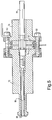
- each of the nozzles 46, 48, 50 in their respective arrays may also be a commercially available electro-mechanical, ultrasonic atomizer (146 in Figure 5) presently available from the Sono-Tek Corporation of Milton, New York.
- this nozzle includes an atomizing horn 72 and a reflecting horn 74 sandwiched about a pair of piezoelectric disks 76, 78 via assembly bolts or other suitable fasteners 80, 82.
- a liquid inlet tube 84 extends through the reflecting horn 74 as well as the disks 76, 78 and is joined with a sliding connection to a liquid feed tube 86 that is threadably secured in the atomizing horn 72.
- the piezoelectric disks 76, 78 expand and contract to produce cyclic expansion and contraction in the atomizing horn 72 and in the liquid feed tube 86. This, in turn, results in a travelling pressure wave that travels axially along the nozzle.
- the length of the nozzle is equal to one wavelength so that a standing wave pattern is established with an antinode at the nozzle discharge orifice or outlet 88.
- a checkerboard-like wave pattern appears at the interface between the liquid and vapor at the outlet 88.
- the wave crests increase to the point where they become unstable and collapse, causing a mist of small droplets to be ejected from the nozzle.
- the frequency of vibration is selected such that the resulting water droplets are small enough to avoid impaction of the compressor hardware, and thus provide droplets for wet compression.
- dual-function nozzles described above are exemplary only, and other suitable dual-function nozzles may be employed.
Landscapes
- Engineering & Computer Science (AREA)
- Mechanical Engineering (AREA)
- General Engineering & Computer Science (AREA)
- Chemical & Material Sciences (AREA)
- Combustion & Propulsion (AREA)
- Structures Of Non-Positive Displacement Pumps (AREA)
- Nozzles (AREA)
- Turbine Rotor Nozzle Sealing (AREA)
- Engine Equipment That Uses Special Cycles (AREA)
- Cleaning By Liquid Or Steam (AREA)
Abstract
Description
Claims (10)
- A combined water-wash and wet compression system for a gas turbine system 10 comprising:a compressor (12) having an inlet defining a flow direction;a plurality of manifolds (38, 40, 42, 52, 54, 56) arranged in proximity to said inlet and arranged transversely of said flow direction;a plurality of dual function nozzles (46, 48, 50) connected to said manifolds, each dual function nozzle adapted to supply, selectively, relatively small droplets for introduction into the compressor for intercooling, or relatively large droplets for impingement on components of the compressor for cleaning said components.
- The system of claim 1 wherein each of said nozzles (46, 48, 50) supplies said relatively small droplets via an atomization function of said dual function nozzles, and supplies said relatively large droplets when said atomization function is deactivated.
- The system of claim 2 wherein said dual function nozzles (46, 48, 50) each comprise a mechanical twin-fluid nozzle, and wherein each nozzle is connected to one of a plurality of air manifolds (52, 54, 56).
- The system of claim 2 wherein said dual function nozzles each comprise an ultrasonic atomizer (146).
- The system of claim 1 wherein said plurality of manifolds each have an array of said dual function nozzles (46, 48, 50).
- The system of claim 5 wherein one of said manifolds (42) and its respective array of dual function nozzles is arranged to direct flow in a direction opposite said flow direction.
- A gas turbine system (10) including a compressor (12), a turbine (14), a generator (16), and a combined water-wash and wet compression system in accordance with any one of claims 1 to 6.
- A method of introducing a liquid into a compressor inlet (24) for providing water wash for cleaning components of a compressor (12), and for providing wet compression for intercooling, said method comprising:a) providing at least one array of dual function nozzles (46, 48, 50) capable of supplying both large and small droplets of the liquid to the inlet (24) of the compressor;b) operating said array of dual function nozzles (46, 48, 50) in a first mode where the droplets of liquid are sufficiently large to impinge on the components of the compressor in a cleaning function; andc) operating said array of dual function nozzles (46, 48, 50) in a second mode where the droplets are sufficiently small to flow past the components of the compressor and into later stages of the compressor where the droplets evaporate for intercooling.
- The method of claim 8 wherein said dual function nozzles (46, 48, 50) each comprise a mechanical twin-fluid nozzle.
- The system of claim 8 wherein said dual function nozzles (46, 48, 50) each comprise an ultrasonic atomizer (146).
Applications Claiming Priority (2)
| Application Number | Priority Date | Filing Date | Title |
|---|---|---|---|
| US703577 | 2000-11-01 | ||
| US09/703,577 US6553768B1 (en) | 2000-11-01 | 2000-11-01 | Combined water-wash and wet-compression system for a gas turbine compressor and related method |
Publications (3)
| Publication Number | Publication Date |
|---|---|
| EP1205640A2 true EP1205640A2 (en) | 2002-05-15 |
| EP1205640A3 EP1205640A3 (en) | 2004-02-04 |
| EP1205640B1 EP1205640B1 (en) | 2008-02-06 |
Family
ID=24825933
Family Applications (1)
| Application Number | Title | Priority Date | Filing Date |
|---|---|---|---|
| EP01309250A Expired - Lifetime EP1205640B1 (en) | 2000-11-01 | 2001-10-31 | Combined system for cooling by water injection and washing of a gas turbine compressor |
Country Status (7)
| Country | Link |
|---|---|
| US (1) | US6553768B1 (en) |
| EP (1) | EP1205640B1 (en) |
| JP (1) | JP4138295B2 (en) |
| KR (1) | KR100671574B1 (en) |
| AT (1) | ATE385538T1 (en) |
| CZ (1) | CZ20013525A3 (en) |
| DE (1) | DE60132691T2 (en) |
Cited By (16)
| Publication number | Priority date | Publication date | Assignee | Title |
|---|---|---|---|---|
| DE10256193A1 (en) * | 2002-12-02 | 2004-06-09 | Alstom Technology Ltd | Method for controlling the liquid injection into an inflow channel of an engine or machine |
| WO2005120953A1 (en) * | 2004-06-14 | 2005-12-22 | Gas Turbine Efficiency Ab | System for washing an aero gas turbine engine |
| WO2007083088A1 (en) * | 2006-01-19 | 2007-07-26 | Power Generation Technology Limited | Method and apparatus for delivering liquid in droplet form |
| US7353655B2 (en) | 2001-12-06 | 2008-04-08 | Alstom Technology Ltd | Method and apparatus for achieving power augmentation in gas turbine using wet compression |
| US7353654B2 (en) | 2001-12-06 | 2008-04-08 | Alstom Technology Ltd | Method and apparatus for achieving power augmentation in gas turbines using wet compression |
| EP1903188A3 (en) * | 2006-09-11 | 2009-11-25 | Gas Turbine Efficiency Sweden AB | System and method for augmenting turbine power output |
| US7712301B1 (en) | 2006-09-11 | 2010-05-11 | Gas Turbine Efficiency Sweden Ab | System and method for augmenting turbine power output |
| US8206478B2 (en) | 2010-04-12 | 2012-06-26 | Pratt & Whitney Line Maintenance Services, Inc. | Portable and modular separator/collector device |
| US8216392B2 (en) | 2007-03-16 | 2012-07-10 | Lufthansa Technik Ag | Device and method for cleaning the core engine of a jet power plant |
| US9162262B2 (en) | 2006-11-28 | 2015-10-20 | Ecoservices, Llc | Automated detection and control system and method for high pressure water wash application and collection applied to aero compressor washing |
| EP3032044A1 (en) * | 2014-12-12 | 2016-06-15 | General Electric Company | Systems and methods for injecting fluids at one or more stages of a multistage component |
| EP2573365A3 (en) * | 2011-09-20 | 2018-01-24 | General Electric Company | Gas turbine inlet air cooling system using ultrasonic water atomization, corresponding cooling method and wet compression system |
| US9932895B2 (en) | 2013-10-10 | 2018-04-03 | Ecoservices, Llc | Radial passage engine wash manifold |
| RU2656801C1 (en) * | 2016-12-12 | 2018-06-06 | Закрытое акционерное общество "Турботект Санкт-Петербург" | External flushing system of gas air-cooling unit |
| EP3399161A1 (en) * | 2017-05-04 | 2018-11-07 | General Electric Company | Compressor circumferential fluid distribution system |
| WO2019229374A1 (en) * | 2018-05-31 | 2019-12-05 | Valeo Systemes Thermiques | Ventilation device for a motor vehicle |
Families Citing this family (44)
| Publication number | Priority date | Publication date | Assignee | Title |
|---|---|---|---|---|
| US6920749B2 (en) * | 2002-03-15 | 2005-07-26 | Parker-Hannifin Corporation | Multi-function simplex/prefilmer nozzle |
| SE522132C2 (en) * | 2002-12-13 | 2004-01-13 | Gas Turbine Efficiency Ab | Cleaning method for stationary gas turbine unit in operation, by spraying cleaning fluid into point in air inlet channel where air velocity has specific minimum value |
| US6932093B2 (en) * | 2003-02-24 | 2005-08-23 | General Electric Company | Methods and apparatus for washing gas turbine engine combustors |
| US6886345B2 (en) * | 2003-07-14 | 2005-05-03 | Siemens Westinghouse Power Corporation | Electrostatic evaporative cooling system |
| SE525924C2 (en) * | 2003-09-25 | 2005-05-24 | Gas Turbine Efficiency Ab | Nozzle and method for cleaning gas turbine compressors |
| US6938405B2 (en) * | 2003-11-13 | 2005-09-06 | General Electric Company | Spray nozzle grid configuration for gas turbine inlet misting system |
| DE10354864B4 (en) | 2003-11-24 | 2018-10-25 | Ansaldo Energia Switzerland AG | nozzle carrier |
| US8066816B2 (en) * | 2005-01-25 | 2011-11-29 | Pratt & Whitney Line Maintenance Services, Inc. | Probe cleaning method and apparatus |
| JP2006266549A (en) * | 2005-03-23 | 2006-10-05 | Osaka Gas Co Ltd | Combustion device for turbine and gas turbine equipped with it |
| US7454913B1 (en) * | 2005-04-29 | 2008-11-25 | Tassone Bruce A | Method and system for introducing fluid into an airstream |
| US20070028947A1 (en) * | 2005-08-04 | 2007-02-08 | General Electric Company | Gas turbine on-line compressor water wash system |
| US7428818B2 (en) * | 2005-09-13 | 2008-09-30 | Gas Turbine Efficiency Ab | System and method for augmenting power output from a gas turbine engine |
| DE102006057383A1 (en) * | 2006-12-04 | 2008-06-05 | Voith Patent Gmbh | Turbine arrangement for energy utilization from sea waves, has chamber that has opening at its lower and upper ends and pipe that opens at both ends to lead air flow |
| US20090320440A1 (en) * | 2007-02-22 | 2009-12-31 | General Electric Company | Wet compression systems in turbine engines |
| US8277647B2 (en) | 2007-12-19 | 2012-10-02 | United Technologies Corporation | Effluent collection unit for engine washing |
| DE102008019892A1 (en) * | 2008-04-21 | 2009-10-29 | Mtu Aero Engines Gmbh | Method for cleaning an aircraft engine |
| US7445677B1 (en) | 2008-05-21 | 2008-11-04 | Gas Turbine Efficiency Sweden Ab | Method and apparatus for washing objects |
| US7647777B2 (en) * | 2008-06-20 | 2010-01-19 | Gas Turbine Efficiency Sweden Ab | Skid architecture for a power augmentation system |
| US8245952B2 (en) | 2009-02-20 | 2012-08-21 | Pratt & Whitney Canada Corp. | Compressor wash nozzle integrated in an inlet case strut |
| US20100287944A1 (en) * | 2009-05-13 | 2010-11-18 | General Electric Company | Availability improvements to heavy fuel fired gas turbines |
| US9016293B2 (en) | 2009-08-21 | 2015-04-28 | Gas Turbine Efficiency Sweden Ab | Staged compressor water wash system |
| US20120134783A1 (en) | 2010-11-30 | 2012-05-31 | General Electric Company | System and method for operating a compressor |
| US8632299B2 (en) | 2010-11-30 | 2014-01-21 | Pratt & Whitney Canada Corp. | Engine case with wash system |
| US9816391B2 (en) | 2012-11-07 | 2017-11-14 | General Electric Company | Compressor wash system with spheroids |
| US9209730B2 (en) | 2013-01-28 | 2015-12-08 | General Electric Company | Gas turbine under frequency response improvement system and method |
| US8778091B1 (en) | 2013-01-31 | 2014-07-15 | Solar Turbines Inc. | Compressor wash with air to turbine cooling passages |
| US9631512B2 (en) | 2013-01-31 | 2017-04-25 | Solar Turbines Incorporated | Gas turbine offline compressor wash with buffer air from combustor |
| US9500098B2 (en) * | 2013-03-13 | 2016-11-22 | Ecoservices, Llc | Rear mounted wash manifold and process |
| FR3005108B1 (en) * | 2013-04-30 | 2018-01-05 | Safran Helicopter Engines | TURBOMACHINE AIR INTAKE CASTER WASHING DEVICE |
| US9951646B2 (en) * | 2013-07-01 | 2018-04-24 | General Electric Company | Gas turbine on-line water wash system and method |
| US9470105B2 (en) | 2013-11-21 | 2016-10-18 | General Electric Company | Automated water wash system for a gas turbine engine |
| US20150159509A1 (en) * | 2013-12-06 | 2015-06-11 | General Electric Company | Method and System for Dispensing Gas Turbine Anticorrosive Protection |
| GB201416928D0 (en) * | 2014-09-25 | 2014-11-12 | Rolls Royce Plc | A gas turbine and a method of washing a gas turbine engine |
| US20160115867A1 (en) * | 2014-10-27 | 2016-04-28 | General Electric Company | Water delivery system for gas turbine compressor |
| US9440353B1 (en) | 2014-12-29 | 2016-09-13 | Google Inc. | Offline determination of robot behavior |
| ES2786301T3 (en) * | 2015-06-24 | 2020-10-09 | Aaf Ltd | System to reduce the inlet air temperature of a device |
| US10428683B2 (en) | 2016-01-05 | 2019-10-01 | General Electric Company | Abrasive gel detergent for cleaning gas turbine engine components |
| US20170198635A1 (en) * | 2016-01-07 | 2017-07-13 | General Electric Company | High flow on-line water wash using sprint nozzle |
| JP7032015B2 (en) | 2016-05-03 | 2022-03-08 | ゼネラル・エレクトリック・カンパニイ | Liquid injection device, and compressor assembly with liquid injection device |
| FR3065993B1 (en) | 2017-05-03 | 2019-05-10 | Ge Energy Products France Snc | INTAKE DUCT FOR GAS OR FUEL TURBINE WITH WATER SATURATION STRUCTURE |
| US11371425B2 (en) | 2020-09-22 | 2022-06-28 | General Electric Company | System and method for cleaning deposit from a component of an assembled, on-wing gas turbine engine |
| US11555413B2 (en) | 2020-09-22 | 2023-01-17 | General Electric Company | System and method for treating an installed and assembled gas turbine engine |
| WO2025080624A1 (en) * | 2023-10-11 | 2025-04-17 | Hart Production Water Disposal, Llc | System and method for separation of solids from a liquid |
| US20250122833A1 (en) * | 2023-10-17 | 2025-04-17 | Ge Infrastructure Technology Llc | Airless sprint & water wash system |
Family Cites Families (27)
| Publication number | Priority date | Publication date | Assignee | Title |
|---|---|---|---|---|
| US2686631A (en) * | 1948-05-08 | 1954-08-17 | United Aircraft Corp | Coolant injection system for gas turbines |
| US2863282A (en) | 1953-01-09 | 1958-12-09 | United Aircraft Corp | Water injection system for gas turbine power plant |
| US2974482A (en) * | 1955-04-25 | 1961-03-14 | Curtiss Wright Corp | Coolant injection system for engines |
| US3623668A (en) * | 1968-03-04 | 1971-11-30 | Gen Electric | Wash manifold |
| US3693347A (en) | 1971-05-12 | 1972-09-26 | Gen Electric | Steam injection in gas turbines having fixed geometry components |
| US3747336A (en) | 1972-03-29 | 1973-07-24 | Gen Electric | Steam injection system for a gas turbine |
| US3785146A (en) | 1972-05-01 | 1974-01-15 | Gen Electric | Self compensating flow divider for a gas turbine steam injection system |
| US4017285A (en) | 1975-10-30 | 1977-04-12 | The Rovac Corporation | Heat pump-refrigeration system with water injection and regenerative heat exchanger |
| US4196020A (en) * | 1978-11-15 | 1980-04-01 | Avco Corporation | Removable wash spray apparatus for gas turbine engine |
| US4259837A (en) | 1979-06-13 | 1981-04-07 | General Electric Company | Water and steam injection system for emission control of gas turbines |
| SE8107798L (en) * | 1981-02-24 | 1982-08-25 | Avco Corp | DOUBLE FUNCTION COUNTER FOR EMERGENCY SYSTEM |
| US4785622A (en) | 1984-12-03 | 1988-11-22 | General Electric Company | Integrated coal gasification plant and combined cycle system with air bleed and steam injection |
| US4928478A (en) | 1985-07-22 | 1990-05-29 | General Electric Company | Water and steam injection in cogeneration system |
| US5011540A (en) * | 1986-12-24 | 1991-04-30 | Mcdermott Peter | Method and apparatus for cleaning a gas turbine engine |
| CH681381A5 (en) * | 1990-02-14 | 1993-03-15 | Turbotect Ag | |
| US5353585A (en) * | 1992-03-03 | 1994-10-11 | Michael Munk | Controlled fog injection for internal combustion system |
| US5537813A (en) | 1992-12-08 | 1996-07-23 | Carolina Power & Light Company | Gas turbine inlet air combined pressure boost and cooling method and apparatus |
| US5454518A (en) * | 1994-03-29 | 1995-10-03 | Munk; Michael | Ultrasonic fogging device |
| JPH08303257A (en) * | 1995-05-09 | 1996-11-19 | Mitsubishi Heavy Ind Ltd | Nox reducing method by wet type washing of gas turbine |
| SE504323C2 (en) * | 1995-06-07 | 1997-01-13 | Gas Turbine Efficiency Ab | Procedures for washing objects such as turbine compressors |
| DE19539774A1 (en) * | 1995-10-26 | 1997-04-30 | Asea Brown Boveri | Intercooled compressor |
| JP2877098B2 (en) * | 1995-12-28 | 1999-03-31 | 株式会社日立製作所 | Gas turbines, combined cycle plants and compressors |
| US5930990A (en) | 1996-05-14 | 1999-08-03 | The Dow Chemical Company | Method and apparatus for achieving power augmentation in gas turbines via wet compression |
| US5867977A (en) * | 1996-05-14 | 1999-02-09 | The Dow Chemical Company | Method and apparatus for achieving power augmentation in gas turbines via wet compression |
| US6012279A (en) * | 1997-06-02 | 2000-01-11 | General Electric Company | Gas turbine engine with water injection |
| GB2333805B (en) * | 1998-01-30 | 2001-09-19 | Speciality Chemical Holdings L | Cleaning method and apparatus |
| US6467252B1 (en) * | 1998-07-24 | 2002-10-22 | General Electric Company | Nozzles for water injection in a turbine engine |
-
2000
- 2000-11-01 US US09/703,577 patent/US6553768B1/en not_active Expired - Lifetime
-
2001
- 2001-10-01 CZ CZ20013525A patent/CZ20013525A3/en unknown
- 2001-10-31 EP EP01309250A patent/EP1205640B1/en not_active Expired - Lifetime
- 2001-10-31 AT AT01309250T patent/ATE385538T1/en not_active IP Right Cessation
- 2001-10-31 DE DE60132691T patent/DE60132691T2/en not_active Expired - Lifetime
- 2001-10-31 JP JP2001333595A patent/JP4138295B2/en not_active Expired - Fee Related
- 2001-10-31 KR KR1020010067423A patent/KR100671574B1/en not_active Expired - Fee Related
Cited By (39)
| Publication number | Priority date | Publication date | Assignee | Title |
|---|---|---|---|---|
| US7784286B2 (en) | 2001-12-06 | 2010-08-31 | Alstom Technology Ltd | Method and apparatus for achieving power augmentation in gas turbines using wet compression |
| US7353655B2 (en) | 2001-12-06 | 2008-04-08 | Alstom Technology Ltd | Method and apparatus for achieving power augmentation in gas turbine using wet compression |
| US7353654B2 (en) | 2001-12-06 | 2008-04-08 | Alstom Technology Ltd | Method and apparatus for achieving power augmentation in gas turbines using wet compression |
| US7353656B2 (en) | 2001-12-06 | 2008-04-08 | Alstom Technology Ltd | Method and apparatus for achieving power augmentation in gas turbines using wet compression |
| US7520137B2 (en) | 2002-12-02 | 2009-04-21 | Alstom Technology Ltd | Method of controlling the injection of liquid into an inflow duct of a prime mover or driven machine |
| DE10256193A1 (en) * | 2002-12-02 | 2004-06-09 | Alstom Technology Ltd | Method for controlling the liquid injection into an inflow channel of an engine or machine |
| US10041372B2 (en) | 2004-06-14 | 2018-08-07 | Ecoservices, Llc | System for washing an aero gas turbine engine |
| EP1897806A3 (en) * | 2004-06-14 | 2008-09-03 | Gas Turbine Efficiency AB | System for washing an aero gas turbine engine |
| US8628627B2 (en) | 2004-06-14 | 2014-01-14 | Ecoservices, Llc | Turboengine water wash system |
| US9708928B2 (en) | 2004-06-14 | 2017-07-18 | Ecoservices, Llc | Turboengine water wash system |
| WO2005120953A1 (en) * | 2004-06-14 | 2005-12-22 | Gas Turbine Efficiency Ab | System for washing an aero gas turbine engine |
| US9657589B2 (en) | 2004-06-14 | 2017-05-23 | Ecoservices, Llc | System for washing an aero gas turbine engine |
| US9376932B2 (en) | 2004-06-14 | 2016-06-28 | Ecoservices, Llc | Turboengine water wash system |
| EP2263809A3 (en) * | 2004-06-14 | 2011-11-02 | Gas Turbine Efficiency AB | System for washing an aero gas turbine engine |
| US9316115B2 (en) | 2004-06-14 | 2016-04-19 | Ecoservices, Llc | Turboengine wash system |
| RU2554188C2 (en) * | 2004-06-14 | 2015-06-27 | ЭКОСЕРВИСИЗ, ЭлЭлСи | Aircraft gas turbine engine flushing system |
| US8479754B2 (en) | 2004-06-14 | 2013-07-09 | Ecoservices, Llc | System for washing an aero gas turbine engine |
| WO2007083088A1 (en) * | 2006-01-19 | 2007-07-26 | Power Generation Technology Limited | Method and apparatus for delivering liquid in droplet form |
| US7703272B2 (en) | 2006-09-11 | 2010-04-27 | Gas Turbine Efficiency Sweden Ab | System and method for augmenting turbine power output |
| EP1903188A3 (en) * | 2006-09-11 | 2009-11-25 | Gas Turbine Efficiency Sweden AB | System and method for augmenting turbine power output |
| CN101487422B (en) * | 2006-09-11 | 2011-08-24 | 燃气涡轮机效率公司 | System for protecting the air intake of a gas turbine |
| EP2275648A1 (en) * | 2006-09-11 | 2011-01-19 | Gas Turbine Efficiency Sweden AB | System and method for augmenting turbine power output |
| US7712301B1 (en) | 2006-09-11 | 2010-05-11 | Gas Turbine Efficiency Sweden Ab | System and method for augmenting turbine power output |
| US9162262B2 (en) | 2006-11-28 | 2015-10-20 | Ecoservices, Llc | Automated detection and control system and method for high pressure water wash application and collection applied to aero compressor washing |
| US8216392B2 (en) | 2007-03-16 | 2012-07-10 | Lufthansa Technik Ag | Device and method for cleaning the core engine of a jet power plant |
| US10634004B2 (en) | 2007-03-16 | 2020-04-28 | Lufthansa Technik Ag | Device and method for cleaning the core engine of a jet engine |
| US10539040B2 (en) | 2007-03-16 | 2020-01-21 | Lufthansa Technik Ag | Device and method for cleaning the core engine of a jet engine |
| US8206478B2 (en) | 2010-04-12 | 2012-06-26 | Pratt & Whitney Line Maintenance Services, Inc. | Portable and modular separator/collector device |
| EP2573365A3 (en) * | 2011-09-20 | 2018-01-24 | General Electric Company | Gas turbine inlet air cooling system using ultrasonic water atomization, corresponding cooling method and wet compression system |
| US9932895B2 (en) | 2013-10-10 | 2018-04-03 | Ecoservices, Llc | Radial passage engine wash manifold |
| US20160169107A1 (en) * | 2014-12-12 | 2016-06-16 | General Electric Company | Systems and methods for injecting fluids at one or more stages of a multi-stage component |
| EP3032044A1 (en) * | 2014-12-12 | 2016-06-15 | General Electric Company | Systems and methods for injecting fluids at one or more stages of a multistage component |
| RU2656801C1 (en) * | 2016-12-12 | 2018-06-06 | Закрытое акционерное общество "Турботект Санкт-Петербург" | External flushing system of gas air-cooling unit |
| CN108800204A (en) * | 2017-05-04 | 2018-11-13 | 通用电气公司 | Compressor axial fluid distribution system |
| EP3399161A1 (en) * | 2017-05-04 | 2018-11-07 | General Electric Company | Compressor circumferential fluid distribution system |
| US11022038B2 (en) | 2017-05-04 | 2021-06-01 | General Electric Company | Compressor circumferential fluid distribution system |
| CN108800204B (en) * | 2017-05-04 | 2022-03-08 | 通用电气公司 | Compressor Circumferential Fluid Distribution System |
| WO2019229374A1 (en) * | 2018-05-31 | 2019-12-05 | Valeo Systemes Thermiques | Ventilation device for a motor vehicle |
| FR3081922A1 (en) * | 2018-05-31 | 2019-12-06 | Valeo Systemes Thermiques | VENTILATION DEVICE FOR A MOTOR VEHICLE |
Also Published As
| Publication number | Publication date |
|---|---|
| JP2002256889A (en) | 2002-09-11 |
| ATE385538T1 (en) | 2008-02-15 |
| DE60132691T2 (en) | 2009-02-05 |
| KR20020034936A (en) | 2002-05-09 |
| CZ20013525A3 (en) | 2002-06-12 |
| EP1205640A3 (en) | 2004-02-04 |
| DE60132691D1 (en) | 2008-03-20 |
| KR100671574B1 (en) | 2007-01-18 |
| US6553768B1 (en) | 2003-04-29 |
| EP1205640B1 (en) | 2008-02-06 |
| JP4138295B2 (en) | 2008-08-27 |
Similar Documents
| Publication | Publication Date | Title |
|---|---|---|
| EP1205640B1 (en) | Combined system for cooling by water injection and washing of a gas turbine compressor | |
| JP4312462B2 (en) | Air auxiliary fuel nozzle | |
| US7938910B2 (en) | Method for washing gas turbine compressor with nozzle | |
| US7033135B2 (en) | Method and apparatus for distributing fluid into a turbomachine | |
| US6539724B2 (en) | Airblast fuel atomization system | |
| US4928479A (en) | Annular combustor with tangential cooling air injection | |
| US5224333A (en) | Simplex airblast fuel injection | |
| US20040187474A1 (en) | Methods and apparatus for operating gas turbine engines | |
| JPH0642426A (en) | Droplet generator | |
| US20040098989A1 (en) | Multi function simplex/prefilmer nozzle | |
| EP1206973B1 (en) | Methods and apparatus for injecting water into gas turbine engines | |
| US20060230746A1 (en) | Turbineless jet engine | |
| JP2001214757A (en) | Gas turbine equipment | |
| JP3929874B2 (en) | High-pressure single-fluid atomizing nozzle for increased output of gas turbines | |
| JP4266239B1 (en) | Two-fluid atomizing nozzle | |
| EP0159153A1 (en) | Air blast fuel injection device | |
| JP2002355583A (en) | Atomization equipment | |
| JP2025069059A (en) | Airless sprint and water cleaning system | |
| GB1578418A (en) | Fuel injectors |
Legal Events
| Date | Code | Title | Description |
|---|---|---|---|
| PUAI | Public reference made under article 153(3) epc to a published international application that has entered the european phase |
Free format text: ORIGINAL CODE: 0009012 |
|
| AK | Designated contracting states |
Kind code of ref document: A2 Designated state(s): AT BE CH CY DE DK ES FI FR GB GR IE IT LI LU MC NL PT SE TR |
|
| AX | Request for extension of the european patent |
Free format text: AL;LT;LV;MK;RO;SI |
|
| PUAL | Search report despatched |
Free format text: ORIGINAL CODE: 0009013 |
|
| AK | Designated contracting states |
Kind code of ref document: A3 Designated state(s): AT BE CH CY DE DK ES FI FR GB GR IE IT LI LU MC NL PT SE TR |
|
| AX | Request for extension of the european patent |
Extension state: AL LT LV MK RO SI |
|
| 17P | Request for examination filed |
Effective date: 20040804 |
|
| AKX | Designation fees paid |
Designated state(s): AT BE CH CY DE DK ES FI FR GB GR IE IT LI LU MC NL PT SE TR |
|
| 17Q | First examination report despatched |
Effective date: 20041201 |
|
| GRAP | Despatch of communication of intention to grant a patent |
Free format text: ORIGINAL CODE: EPIDOSNIGR1 |
|
| GRAS | Grant fee paid |
Free format text: ORIGINAL CODE: EPIDOSNIGR3 |
|
| GRAA | (expected) grant |
Free format text: ORIGINAL CODE: 0009210 |
|
| AK | Designated contracting states |
Kind code of ref document: B1 Designated state(s): AT BE CH CY DE DK ES FI FR GB GR IE IT LI LU MC NL PT SE TR |
|
| REG | Reference to a national code |
Ref country code: GB Ref legal event code: FG4D |
|
| REG | Reference to a national code |
Ref country code: CH Ref legal event code: EP |
|
| REG | Reference to a national code |
Ref country code: IE Ref legal event code: FG4D |
|
| REF | Corresponds to: |
Ref document number: 60132691 Country of ref document: DE Date of ref document: 20080320 Kind code of ref document: P |
|
| REG | Reference to a national code |
Ref country code: CH Ref legal event code: NV Representative=s name: SERVOPATENT GMBH |
|
| REG | Reference to a national code |
Ref country code: SE Ref legal event code: TRGR |
|
| PG25 | Lapsed in a contracting state [announced via postgrant information from national office to epo] |
Ref country code: FI Free format text: LAPSE BECAUSE OF FAILURE TO SUBMIT A TRANSLATION OF THE DESCRIPTION OR TO PAY THE FEE WITHIN THE PRESCRIBED TIME-LIMIT Effective date: 20080206 Ref country code: ES Free format text: LAPSE BECAUSE OF FAILURE TO SUBMIT A TRANSLATION OF THE DESCRIPTION OR TO PAY THE FEE WITHIN THE PRESCRIBED TIME-LIMIT Effective date: 20080517 |
|
| PG25 | Lapsed in a contracting state [announced via postgrant information from national office to epo] |
Ref country code: AT Free format text: LAPSE BECAUSE OF FAILURE TO SUBMIT A TRANSLATION OF THE DESCRIPTION OR TO PAY THE FEE WITHIN THE PRESCRIBED TIME-LIMIT Effective date: 20080206 |
|
| ET | Fr: translation filed | ||
| PG25 | Lapsed in a contracting state [announced via postgrant information from national office to epo] |
Ref country code: BE Free format text: LAPSE BECAUSE OF FAILURE TO SUBMIT A TRANSLATION OF THE DESCRIPTION OR TO PAY THE FEE WITHIN THE PRESCRIBED TIME-LIMIT Effective date: 20080206 |
|
| PG25 | Lapsed in a contracting state [announced via postgrant information from national office to epo] |
Ref country code: PT Free format text: LAPSE BECAUSE OF FAILURE TO SUBMIT A TRANSLATION OF THE DESCRIPTION OR TO PAY THE FEE WITHIN THE PRESCRIBED TIME-LIMIT Effective date: 20080707 Ref country code: DK Free format text: LAPSE BECAUSE OF FAILURE TO SUBMIT A TRANSLATION OF THE DESCRIPTION OR TO PAY THE FEE WITHIN THE PRESCRIBED TIME-LIMIT Effective date: 20080206 |
|
| PLBE | No opposition filed within time limit |
Free format text: ORIGINAL CODE: 0009261 |
|
| STAA | Information on the status of an ep patent application or granted ep patent |
Free format text: STATUS: NO OPPOSITION FILED WITHIN TIME LIMIT |
|
| 26N | No opposition filed |
Effective date: 20081107 |
|
| PG25 | Lapsed in a contracting state [announced via postgrant information from national office to epo] |
Ref country code: MC Free format text: LAPSE BECAUSE OF NON-PAYMENT OF DUE FEES Effective date: 20081031 |
|
| PG25 | Lapsed in a contracting state [announced via postgrant information from national office to epo] |
Ref country code: CY Free format text: LAPSE BECAUSE OF FAILURE TO SUBMIT A TRANSLATION OF THE DESCRIPTION OR TO PAY THE FEE WITHIN THE PRESCRIBED TIME-LIMIT Effective date: 20080206 |
|
| PG25 | Lapsed in a contracting state [announced via postgrant information from national office to epo] |
Ref country code: IE Free format text: LAPSE BECAUSE OF NON-PAYMENT OF DUE FEES Effective date: 20081031 |
|
| PG25 | Lapsed in a contracting state [announced via postgrant information from national office to epo] |
Ref country code: LU Free format text: LAPSE BECAUSE OF NON-PAYMENT OF DUE FEES Effective date: 20081031 |
|
| PG25 | Lapsed in a contracting state [announced via postgrant information from national office to epo] |
Ref country code: TR Free format text: LAPSE BECAUSE OF FAILURE TO SUBMIT A TRANSLATION OF THE DESCRIPTION OR TO PAY THE FEE WITHIN THE PRESCRIBED TIME-LIMIT Effective date: 20080206 |
|
| PG25 | Lapsed in a contracting state [announced via postgrant information from national office to epo] |
Ref country code: GR Free format text: LAPSE BECAUSE OF FAILURE TO SUBMIT A TRANSLATION OF THE DESCRIPTION OR TO PAY THE FEE WITHIN THE PRESCRIBED TIME-LIMIT Effective date: 20080507 |
|
| REG | Reference to a national code |
Ref country code: FR Ref legal event code: PLFP Year of fee payment: 15 |
|
| PGFP | Annual fee paid to national office [announced via postgrant information from national office to epo] |
Ref country code: GB Payment date: 20151027 Year of fee payment: 15 |
|
| PGFP | Annual fee paid to national office [announced via postgrant information from national office to epo] |
Ref country code: NL Payment date: 20151026 Year of fee payment: 15 Ref country code: SE Payment date: 20151028 Year of fee payment: 15 |
|
| REG | Reference to a national code |
Ref country code: FR Ref legal event code: PLFP Year of fee payment: 16 |
|
| REG | Reference to a national code |
Ref country code: NL Ref legal event code: MM Effective date: 20161101 |
|
| GBPC | Gb: european patent ceased through non-payment of renewal fee |
Effective date: 20161031 |
|
| REG | Reference to a national code |
Ref country code: SE Ref legal event code: EUG |
|
| PG25 | Lapsed in a contracting state [announced via postgrant information from national office to epo] |
Ref country code: GB Free format text: LAPSE BECAUSE OF NON-PAYMENT OF DUE FEES Effective date: 20161031 |
|
| PG25 | Lapsed in a contracting state [announced via postgrant information from national office to epo] |
Ref country code: NL Free format text: LAPSE BECAUSE OF NON-PAYMENT OF DUE FEES Effective date: 20161101 Ref country code: SE Free format text: LAPSE BECAUSE OF NON-PAYMENT OF DUE FEES Effective date: 20161101 |
|
| REG | Reference to a national code |
Ref country code: FR Ref legal event code: PLFP Year of fee payment: 17 |
|
| REG | Reference to a national code |
Ref country code: FR Ref legal event code: PLFP Year of fee payment: 18 |
|
| PGFP | Annual fee paid to national office [announced via postgrant information from national office to epo] |
Ref country code: FR Payment date: 20180920 Year of fee payment: 18 Ref country code: IT Payment date: 20180919 Year of fee payment: 18 |
|
| PGFP | Annual fee paid to national office [announced via postgrant information from national office to epo] |
Ref country code: CH Payment date: 20180925 Year of fee payment: 18 |
|
| PGFP | Annual fee paid to national office [announced via postgrant information from national office to epo] |
Ref country code: DE Payment date: 20180819 Year of fee payment: 18 |
|
| REG | Reference to a national code |
Ref country code: DE Ref legal event code: R119 Ref document number: 60132691 Country of ref document: DE |
|
| REG | Reference to a national code |
Ref country code: CH Ref legal event code: PL |
|
| PG25 | Lapsed in a contracting state [announced via postgrant information from national office to epo] |
Ref country code: LI Free format text: LAPSE BECAUSE OF NON-PAYMENT OF DUE FEES Effective date: 20191031 Ref country code: CH Free format text: LAPSE BECAUSE OF NON-PAYMENT OF DUE FEES Effective date: 20191031 Ref country code: DE Free format text: LAPSE BECAUSE OF NON-PAYMENT OF DUE FEES Effective date: 20200501 |
|
| PG25 | Lapsed in a contracting state [announced via postgrant information from national office to epo] |
Ref country code: IT Free format text: LAPSE BECAUSE OF NON-PAYMENT OF DUE FEES Effective date: 20191031 Ref country code: FR Free format text: LAPSE BECAUSE OF NON-PAYMENT OF DUE FEES Effective date: 20191031 |