EP1205638A2 - Inlet guide vane and shroud support contact - Google Patents
Inlet guide vane and shroud support contact Download PDFInfo
- Publication number
- EP1205638A2 EP1205638A2 EP01309382A EP01309382A EP1205638A2 EP 1205638 A2 EP1205638 A2 EP 1205638A2 EP 01309382 A EP01309382 A EP 01309382A EP 01309382 A EP01309382 A EP 01309382A EP 1205638 A2 EP1205638 A2 EP 1205638A2
- Authority
- EP
- European Patent Office
- Prior art keywords
- shroud
- vane
- retainer
- bushing
- arcuate
- Prior art date
- Legal status (The legal status is an assumption and is not a legal conclusion. Google has not performed a legal analysis and makes no representation as to the accuracy of the status listed.)
- Granted
Links
Images


Classifications
-
- F—MECHANICAL ENGINEERING; LIGHTING; HEATING; WEAPONS; BLASTING
- F01—MACHINES OR ENGINES IN GENERAL; ENGINE PLANTS IN GENERAL; STEAM ENGINES
- F01D—NON-POSITIVE DISPLACEMENT MACHINES OR ENGINES, e.g. STEAM TURBINES
- F01D9/00—Stators
- F01D9/02—Nozzles; Nozzle boxes; Stator blades; Guide conduits, e.g. individual nozzles
- F01D9/04—Nozzles; Nozzle boxes; Stator blades; Guide conduits, e.g. individual nozzles forming ring or sector
- F01D9/042—Nozzles; Nozzle boxes; Stator blades; Guide conduits, e.g. individual nozzles forming ring or sector fixing blades to stators
-
- F—MECHANICAL ENGINEERING; LIGHTING; HEATING; WEAPONS; BLASTING
- F01—MACHINES OR ENGINES IN GENERAL; ENGINE PLANTS IN GENERAL; STEAM ENGINES
- F01D—NON-POSITIVE DISPLACEMENT MACHINES OR ENGINES, e.g. STEAM TURBINES
- F01D17/00—Regulating or controlling by varying flow
- F01D17/10—Final actuators
- F01D17/12—Final actuators arranged in stator parts
- F01D17/14—Final actuators arranged in stator parts varying effective cross-sectional area of nozzles or guide conduits
- F01D17/16—Final actuators arranged in stator parts varying effective cross-sectional area of nozzles or guide conduits by means of nozzle vanes
- F01D17/162—Final actuators arranged in stator parts varying effective cross-sectional area of nozzles or guide conduits by means of nozzle vanes for axial flow, i.e. the vanes turning around axes which are essentially perpendicular to the rotor centre line
-
- F—MECHANICAL ENGINEERING; LIGHTING; HEATING; WEAPONS; BLASTING
- F04—POSITIVE - DISPLACEMENT MACHINES FOR LIQUIDS; PUMPS FOR LIQUIDS OR ELASTIC FLUIDS
- F04D—NON-POSITIVE-DISPLACEMENT PUMPS
- F04D29/00—Details, component parts, or accessories
- F04D29/40—Casings; Connections of working fluid
- F04D29/52—Casings; Connections of working fluid for axial pumps
- F04D29/54—Fluid-guiding means, e.g. diffusers
- F04D29/56—Fluid-guiding means, e.g. diffusers adjustable
- F04D29/563—Fluid-guiding means, e.g. diffusers adjustable specially adapted for elastic fluid pumps
-
- Y—GENERAL TAGGING OF NEW TECHNOLOGICAL DEVELOPMENTS; GENERAL TAGGING OF CROSS-SECTIONAL TECHNOLOGIES SPANNING OVER SEVERAL SECTIONS OF THE IPC; TECHNICAL SUBJECTS COVERED BY FORMER USPC CROSS-REFERENCE ART COLLECTIONS [XRACs] AND DIGESTS
- Y02—TECHNOLOGIES OR APPLICATIONS FOR MITIGATION OR ADAPTATION AGAINST CLIMATE CHANGE
- Y02T—CLIMATE CHANGE MITIGATION TECHNOLOGIES RELATED TO TRANSPORTATION
- Y02T50/00—Aeronautics or air transport
- Y02T50/60—Efficient propulsion technologies, e.g. for aircraft
-
- Y—GENERAL TAGGING OF NEW TECHNOLOGICAL DEVELOPMENTS; GENERAL TAGGING OF CROSS-SECTIONAL TECHNOLOGIES SPANNING OVER SEVERAL SECTIONS OF THE IPC; TECHNICAL SUBJECTS COVERED BY FORMER USPC CROSS-REFERENCE ART COLLECTIONS [XRACs] AND DIGESTS
- Y10—TECHNICAL SUBJECTS COVERED BY FORMER USPC
- Y10T—TECHNICAL SUBJECTS COVERED BY FORMER US CLASSIFICATION
- Y10T29/00—Metal working
- Y10T29/49—Method of mechanical manufacture
- Y10T29/49826—Assembling or joining
- Y10T29/49863—Assembling or joining with prestressing of part
- Y10T29/4987—Elastic joining of parts
- Y10T29/49872—Confining elastic part in socket
-
- Y—GENERAL TAGGING OF NEW TECHNOLOGICAL DEVELOPMENTS; GENERAL TAGGING OF CROSS-SECTIONAL TECHNOLOGIES SPANNING OVER SEVERAL SECTIONS OF THE IPC; TECHNICAL SUBJECTS COVERED BY FORMER USPC CROSS-REFERENCE ART COLLECTIONS [XRACs] AND DIGESTS
- Y10—TECHNICAL SUBJECTS COVERED BY FORMER USPC
- Y10T—TECHNICAL SUBJECTS COVERED BY FORMER US CLASSIFICATION
- Y10T29/00—Metal working
- Y10T29/49—Method of mechanical manufacture
- Y10T29/49826—Assembling or joining
- Y10T29/49908—Joining by deforming
- Y10T29/49938—Radially expanding part in cavity, aperture, or hollow body
Definitions
- This invention relates generally to gas turbine engines and more particularly to inlet guide vanes and shroud supports for such engines.
- a turbofan gas turbine engine used for powering an aircraft in flight typically includes, in serial flow communication, a fan, a low pressure compressor or booster, a high pressure compressor, a combustor, a high pressure turbine, and a low pressure turbine.
- the combustor generates combustion gases that are channeled in succession to the high pressure turbine where they are expanded to drive the high pressure turbine, and then to the low pressure turbine where they are further expanded to drive the low pressure turbine.
- the high pressure turbine is drivingly connected to the high pressure compressor via a first rotor shaft
- the low pressure turbine is drivingly connected to both the fan and the booster via a second rotor shaft.
- the high pressure compressor typically includes a series of stator vane stages used to compress air for engine and aircraft use.
- the first compressor stage adjacent to the booster is the inlet guide vane stage formed of a plurality of circumferentially arranged cantilevered inlet guide vanes.
- the inlet guide vanes may be actuated through a control system so as to optimize air flow for power and stall avoidance purposes.
- the guide vanes are retained between a stator case and an inner vane shroud.
- the stator case is coupled to the engine case.
- the space between the stator case and the shroud defines the volume of air passing through the high pressure compressor.
- the shroud provides an aerodynamic flowpath boundary of the high pressure compressor.
- the inlet guide vanes as well as other downstream stator vanes are variably actuated through the operation of one or more controllable vane actuators.
- An outer trunnion or spindle of the vane passes through the stator case and is coupled to a lever arm.
- the lever arm is coupled to an actuation ring that is connected to a vane actuator.
- One or more vane actuators effect movement to the series of circumferentially arranged stator vanes of each compressor stage.
- the vane is retained to the stator case through a combination of bushings, washers, and a lock nut that is threaded onto the outer trunnion.
- the vane also includes an inner trunnion at its opposing end. That inner trunnion is used to retain the vane to the inner vane shroud. In most cases, a plurality of vanes spanned and retained by one shroud section. A plurality of shroud sections extends completely around the inner circumference of the compressor to retain all vanes.
- the inner trunnion of the vane is removably affixed to the shroud by way of a bushing.
- two shroud pins one at each of the inner trunnions of the two end vanes of a particular shroud section, secure the shroud section to that set of vanes.
- a shroud section made for five is secured to the inner trunnions of those five vanes by way of bushings. That is the only securing mechanism for the three interior vanes.
- the two outer vanes of the shroud section each has a modified inner trunnion or spindle with a hemispherical cut-out for accepting a retaining pin.
- the retaining pin passes transversely through the bushing and is designed to remain captured in the hemispherical cutout of the modified inner trunnion.
- shroud retainer is designed to capture flanges or wings of the shroud sections below the inner trunnion.
- shroud retainers are formed to provide coverage to approximately one-quarter of the inner circumference of the compressor stage. That is, they extend approximately 90° of the inner 360° circumference, thereby capturing a plurality of shroud sections.
- Linking a series of vanes together using the shroud sections and then coupling a series of shroud sections together using the set of shroud retainers is intended tighten together the vanes. That along with the shroud pins is designed to reduce vane loosening, much like the spokes of a bicycle wheel are captured and retained together on a wheel hub.
- the above-mentioned need is met by the present invention, which provides a coupling assembly for retaining a rotatable structure to a fixed casing.
- the coupling or contact assembly includes a bushing designed to pass through the port of the segmented arcuate inner shrouds and to retain the rotatable structure and a washer disposed within the port and positioned by way of a recessed hole in the shroud.
- a retainer removably coupleable to the inner shroud and disposed thereon captures the bushing between the inner shroud and the retainer.
- the assembly is suitable for use with turbofan engines having compressor stages.
- the inlet guide vane stage of the compressor includes a plurality of variable guide vanes disposed between the stator casing and the inner vane shroud.
- the contact assembly of the present invention includes for each vane-to-shroud contact assembly a bushing removably retained within a port of the vane shroud for receiving the trunnion of the vane.
- the assembly also includes a washer positioned between a contact face of either the bushing or the inner shroud recessed hole shoulder and a trunnion button of the vane.
- a shroud sealing retainer removably coupleable to the outer surface of the shroud and disposed thereon captures the bushing between the washer and that retainer.
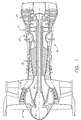
- Figure 1 is a partial schematic cross-sectional view of a turbofan engine incorporating the inlet guide vane coupling system of the present invention.
- Figure 2 is a partial cut-away perspective view of the high pressure compressor section of the engine of Figure 1.
- Figure 3 is a partial exploded perspective view of the inlet guide vane coupling system of the engine of Figure 1.
- Figure 4 is a simplified side view of an inlet guide vane and showing the vane-to-shroud coupling mechanism of the present invention.
- Figure 5 is a cross-sectional side view of an inlet guide vane showing the vane-to-shroud coupling mechanism of the present invention.
- Figure 6 is an exploded side view of a portion of an inlet guide vane showing the inner trunnion retained by the contact mechanism of the present invention.
- Figure 1 illustrates a longitudinal cross-sectional view of a high bypass ratio turbofan engine 10.
- the engine 10 includes, in serial axial flow communication about a longitudinal centerline axis 12, a fan 14, a booster 16, a high pressure compressor 18, a combustor 20, a high pressure turbine 22, and a low pressure turbine 24.
- the high pressure turbine 22 is drivingly connected to the high pressure compressor 18 with a first rotor shaft 26, and the low pressure turbine 24 is drivingly connected to both the booster 16 and the fan 14 with a second rotor shaft 28, which is disposed within the first rotor shaft 26.
- ambient air passes through the fan 14, the booster 16, and the compressor 18 to be pressurized in succession. Some of the ambient air is bled off for supplemental functions while the primary pressurized air stream enters the combustor 20 where it is mixed with fuel and burned to provide a high energy stream of hot combustion gases.
- the high-energy gas stream passes through the high-pressure turbine 22 where it is further expanded, with energy being extracted to drive the first rotor shaft 26.
- the gas stream then passes through the low-pressure turbine 24 where energy is extracted to drive the second rotor shaft 28 and, thus, the fan 14.
- Spent products of combustion and unused gas pass out of the engine 10 through an exhaust duct.
- the compressor 18 includes an inlet guide vane stage 30 and a set of following variable vane stator stages 32, 34, and 36.
- the annular dimensions of each of stages 30-36 becomes increasingly smaller to compress the air for use in following engine stages.
- Each of the stages of the compressor 18 includes a set of circumferentially arranged vanes 38 captured between a stator case 40 of the compressor 18 and a vane shroud 42.
- the shroud 42 is actually formed of a set of shroud sections 42.
- the vanes 38 are variably actuated by a set of variable vane actuators 44, 46.
- the vanes 38 are coupled through the stator case 40 to the actuators 44,46 by way of a vane outer trunnion 48.
- the outer trunnion 48 passes through a stator case port 50 and is retained by way of an inner bushing 52 and an outer nut 54.
- a lever arm 56 is captured between the bushing 52 and the outer nut 54.
- the lever arm 56 is coupled to the vane actuators 44,46 through linkage arms 58.
- each shroud section includes a plurality of shroud ports 60, each port 60 designed to accept an inner trunnion 62 of individual ones of the vanes 38.
- the inner trunnion 62 includes a contact shoulder or trunnion button 64 that resides in a shroud port recess 66 having a recess shoulder.
- the inner trunnion 62 is initially captured in the port 60 using a shroud bushing 68 that fits in the port 60.
- a shroud washer 70 forms an intermediate contact area between a bushing face of the trunnion button 64 and a trunnion face of the shroud bushing 68.
- the washer 70 prevents the shroud section 42 from moving upward and significantly increases the capturing contact area between that capturing component and the inner trunnion 62. This increases the longevity of the guide vane system and reduces maintenance obligations.
- the shroud sections 42 are further coupled together with a shroud seal retainer 74.
- the retainer 74 includes channel sections 76,78 designed to capture shoulders 80,82 of the shroud section 42.
- the retainer 74 extends approximately one-half of the entire inner circumference of the compressor 18, as shown in Figure 3. This span of the retainer 74 is substantially greater than the span of the 90° retainers previously in use. It more effectively ties together groups of shroud sections 42 and, thereby, groups of vanes 38. The result is a spoke effect on the interconnected cantilevered vanes 38.
- the longer span of the retainer 74 also provides improved prevention of movement of the shroud sections 42 downward away from the inner space of the compressor 18. Actuation and vibration effects on the shroud-to-vane interfaces are therefore reduced.
Landscapes
- Engineering & Computer Science (AREA)
- Mechanical Engineering (AREA)
- General Engineering & Computer Science (AREA)
- Structures Of Non-Positive Displacement Pumps (AREA)
- Turbine Rotor Nozzle Sealing (AREA)
- Rotary Pumps (AREA)
Abstract
Description
Claims (10)
- A contact assembly for retaining a rotatable structure (38) in a port (60) of an inner shroud (42), the assembly comprising:a bushing (68) designed to pass through the port (60) of the inner shroud (42) and to retain the rotatable structure (38);a washer (70) disposed within the port (60) and mounted on the bushing (68); anda retainer (74) removably coupleable to the inner shroud (42) and disposed thereon to capture said bushing (68) between said washer (70) and said retainer (74).
- The contact assembly of claim 1 wherein the inner shroud (42) is of arcuate configuration and said retainer (74) is of corresponding arcuate configuration.
- The contact assembly of claim 2 wherein the inner shroud (42) is formed of a plurality of arcuate sections (42) and said retainer (74) is a unitary component spanning the plurality of arcuate sections (42).
- The contact assembly of claim 3 wherein the plurality of arcuate sections (42) forms an annulus and said retainer (74) includes a pair of said retainers (74), wherein each of said retainers (74) spans about one-half of the entire outer circumference of the annulus.
- A gas turbine engine having a compressor (18) including an inlet guide vane stage (30), wherein the inlet guide vane stage (30) includes a plurality of variable guide vanes (38) disposed between a stator casing (40) and an inner vane shroud (42), wherein the shroud (42) includes a recessed hole shoulder (66), and for each vane (38) a vane-to-shroud contact assembly, the contact assembly comprising:a bushing (68) removably retained within a port (60) of the vane shroud (42) for receiving a trunnion (62) of the vane (38);a washer (70) positioned between a face of said bushing (68) or the recessed hole shoulder (66) of the inner shroud (42) and a trunnion button (64) of the vane (38); anda shroud sealing retainer (74) removably coupleable to an outer surface of the shroud (80,82) and disposed thereon to capture said bushing (68) between the shroud (42) and said retainer (74).
- The contact assembly of claim 5 wherein the shroud (42) is of arcuate configuration and said retainer (74) is of corresponding arcuate configuration.
- The contact assembly of claim 6 wherein the shroud (42) is formed of a plurality of arcuate shroud sections (42) and said retainer (74) is a unitary component spanning the plurality of arcuate shroud sections (42).
- The contact assembly of claim 7 wherein the plurality of arcuate shroud sections (42) forms an annulus and said retainer (74) includes a pair of said retainers (74), wherein each of said retainers (74) spans about one-half of the entire outer circumference of the annulus.
- The contact assembly of claim 7 wherein each of the arcuate shroud sections (42) includes opposing shroud shoulders (80,82), said retainer (74) including capture channels (76,78) for retaining the shroud shoulders (80,82) therein.
- A method for coupling a guide vane (38) of a compressor (18) of a gas turbine engine (10) to a capturing shroud (42), the capturing shroud (42) including a recessed hole shoulder (66), the method comprising the steps of:applying a washer (70) to an inner trunnion (62) of the guide vane (38);capturing said washer (70) between a bushing (68) disposed within a capture port (60) of the shroud (42) or the recessed hole shoulder (66) of the shroud (42) and a lower end of the guide vane (38); andapplying a shroud retainer (74) to the capturing shroud (42) to retain said bushing (68) between said retainer (74) and the shroud (42).
Applications Claiming Priority (2)
| Application Number | Priority Date | Filing Date | Title |
|---|---|---|---|
| US09/710,677 US6413043B1 (en) | 2000-11-09 | 2000-11-09 | Inlet guide vane and shroud support contact |
| US710677 | 2000-11-09 |
Publications (3)
| Publication Number | Publication Date |
|---|---|
| EP1205638A2 true EP1205638A2 (en) | 2002-05-15 |
| EP1205638A3 EP1205638A3 (en) | 2004-01-07 |
| EP1205638B1 EP1205638B1 (en) | 2007-07-18 |
Family
ID=24855051
Family Applications (1)
| Application Number | Title | Priority Date | Filing Date |
|---|---|---|---|
| EP01309382A Expired - Lifetime EP1205638B1 (en) | 2000-11-09 | 2001-11-06 | Inlet guide vane and shroud support contact |
Country Status (6)
| Country | Link |
|---|---|
| US (1) | US6413043B1 (en) |
| EP (1) | EP1205638B1 (en) |
| JP (1) | JP4118041B2 (en) |
| AT (1) | ATE367512T1 (en) |
| DE (1) | DE60129398T2 (en) |
| ES (1) | ES2288501T3 (en) |
Cited By (8)
| Publication number | Priority date | Publication date | Assignee | Title |
|---|---|---|---|---|
| FR2890707A1 (en) * | 2005-09-14 | 2007-03-16 | Snecma | SOCKET FOR VANE PIVOT WITH VARIABLE SETTING ANGLE FOR TURBOMACHINE |
| EP1790827A1 (en) * | 2005-11-29 | 2007-05-30 | General Electric Company | Tip shroud attachment for stator vane |
| GB2466214A (en) * | 2008-12-12 | 2010-06-16 | Gen Electric | A bushing and clock spring assembly for a movable turbine vane |
| CN103154524A (en) * | 2010-08-11 | 2013-06-12 | 航空技术空间股份有限公司 | Axial turbomachine compressor outer casing |
| WO2013150224A1 (en) * | 2012-04-03 | 2013-10-10 | Snecma | Variable pitch rectifier for a turbomachine compressor comprising two inner rings |
| CN104727863A (en) * | 2013-12-20 | 2015-06-24 | 航空技术空间股份有限公司 | Strip for abradable in a compressor turbine |
| EP3098390A1 (en) * | 2015-05-15 | 2016-11-30 | United Technologies Corporation | Vane strut positioning and securing systems including locking washers |
| CN103154524B (en) * | 2010-08-11 | 2016-11-30 | 赛峰航空助推器股份有限公司 | The shell of axial turbomachine compressor |
Families Citing this family (38)
| Publication number | Priority date | Publication date | Assignee | Title |
|---|---|---|---|---|
| FR2857404B1 (en) * | 2003-07-10 | 2007-03-09 | Snecma Moteurs | AUBING ROTATION GUIDING DEVICE WITH VARIABLE TIMING IN A TURBOMACHINE |
| US7360991B2 (en) * | 2004-06-09 | 2008-04-22 | General Electric Company | Methods and apparatus for fabricating gas turbine engines |
| US7419121B2 (en) * | 2004-12-09 | 2008-09-02 | Honeywell International Inc. | Integrated mount duct for use with airborne auxiliary power units and other turbomachines |
| GB0504588D0 (en) * | 2005-03-05 | 2005-04-13 | Rolls Royce Plc | Pivot ring |
| US7588415B2 (en) * | 2005-07-20 | 2009-09-15 | United Technologies Corporation | Synch ring variable vane synchronizing mechanism for inner diameter vane shroud |
| US7753647B2 (en) * | 2005-07-20 | 2010-07-13 | United Technologies Corporation | Lightweight cast inner diameter vane shroud for variable stator vanes |
| US7690889B2 (en) * | 2005-07-20 | 2010-04-06 | United Technologies Corporation | Inner diameter variable vane actuation mechanism |
| US7628579B2 (en) * | 2005-07-20 | 2009-12-08 | United Technologies Corporation | Gear train variable vane synchronizing mechanism for inner diameter vane shroud |
| US7665959B2 (en) * | 2005-07-20 | 2010-02-23 | United Technologies Corporation | Rack and pinion variable vane synchronizing mechanism for inner diameter vane shroud |
| DE102005040574A1 (en) * | 2005-08-26 | 2007-03-15 | Rolls-Royce Deutschland Ltd & Co Kg | Gap control device for a gas turbine |
| FR2896012B1 (en) * | 2006-01-06 | 2008-04-04 | Snecma Sa | ANTI-WEAR DEVICE FOR A TURNBUCKLE COMPRESSOR VARIABLE TUNING ANGLE GUIDING PIVOT PIVOT |
| FR2902822B1 (en) * | 2006-06-21 | 2008-08-22 | Snecma Sa | STATOR BEARING FOR STATOR WITH VARIABLE SHAFT |
| JP5228311B2 (en) * | 2006-11-08 | 2013-07-03 | 株式会社Ihi | Compressor vane |
| US7854586B2 (en) * | 2007-05-31 | 2010-12-21 | United Technologies Corporation | Inlet guide vane inner air seal surge retaining mechanism |
| US8197196B2 (en) * | 2007-08-31 | 2012-06-12 | General Electric Company | Bushing and clock spring assembly for moveable turbine vane |
| US7762086B2 (en) * | 2008-03-12 | 2010-07-27 | United Technologies Corporation | Nozzle extension assembly for ground and flight testing |
| US8215902B2 (en) * | 2008-10-15 | 2012-07-10 | United Technologies Corporation | Scalable high pressure compressor variable vane actuation arm |
| US8328512B2 (en) * | 2009-06-05 | 2012-12-11 | United Technologies Corporation | Inner diameter shroud assembly for variable inlet guide vane structure in a gas turbine engine |
| US20110176913A1 (en) * | 2010-01-19 | 2011-07-21 | Stephen Paul Wassynger | Non-linear asymmetric variable guide vane schedule |
| US8858165B2 (en) | 2010-09-30 | 2014-10-14 | Rolls-Royce Corporation | Seal arrangement for variable vane |
| US8734091B2 (en) * | 2011-04-27 | 2014-05-27 | General Electric Company | Axial compressor with arrangement for bleeding air from variable stator vane stages |
| US9074489B2 (en) * | 2012-03-26 | 2015-07-07 | Pratt & Whitney Canada Corp. | Connector assembly for variable inlet guide vanes and method |
| US20130287550A1 (en) * | 2012-04-25 | 2013-10-31 | General Electric Company | Compressor of a gas turbine system |
| US9140133B2 (en) | 2012-08-14 | 2015-09-22 | United Technologies Corporation | Threaded full ring inner air-seal |
| US10161407B2 (en) | 2013-06-14 | 2018-12-25 | United Technologies Corporation | Radial fastening of tubular synchronizing rings |
| WO2015077011A1 (en) | 2013-11-19 | 2015-05-28 | United Technologies Corporation | Multi-element inner shroud extension for a turbo-machine |
| EP3090142B1 (en) | 2013-12-11 | 2019-04-03 | United Technologies Corporation | Variable vane positioning apparatus for a gas turbine engine |
| JP2016061261A (en) * | 2014-09-19 | 2016-04-25 | 三菱重工業株式会社 | Centrifugal compressor |
| DE102014223975A1 (en) * | 2014-11-25 | 2016-05-25 | MTU Aero Engines AG | Guide vane ring and turbomachine |
| US10794219B2 (en) | 2017-09-14 | 2020-10-06 | Rolls-Royce Corporation | Axial case ring to maximize thrust bushing contact area of variable vane |
| DE102017222209A1 (en) * | 2017-12-07 | 2019-06-13 | MTU Aero Engines AG | Guide vane connection and turbomachine |
| US11028709B2 (en) * | 2018-09-18 | 2021-06-08 | General Electric Company | Airfoil shroud assembly using tenon with externally threaded stud and nut |
| US11608747B2 (en) * | 2021-01-07 | 2023-03-21 | General Electric Company | Split shroud for vibration reduction |
| FR3133367B1 (en) * | 2022-03-11 | 2024-08-23 | Safran Aircraft Engines | AERONAUTICAL PROPELLER |
| CN114962338B (en) * | 2022-04-27 | 2024-04-12 | 四川航天中天动力装备有限责任公司 | Split stator casing structure of turbojet engine and assembly method thereof |
| US12078071B1 (en) * | 2023-02-21 | 2024-09-03 | Rolls-Royce Corporation | Segmented compressor inner band for variable vanes in gas turbine engines |
| US11879480B1 (en) | 2023-04-07 | 2024-01-23 | Rolls-Royce North American Technologies Inc. | Sectioned compressor inner band for variable pitch vane assemblies in gas turbine engines |
| DE102023121106A1 (en) | 2023-08-08 | 2025-02-13 | MTU Aero Engines AG | Guide vane arrangement of a turbomachine and method for assembling a guide vane arrangement |
Family Cites Families (6)
| Publication number | Priority date | Publication date | Assignee | Title |
|---|---|---|---|---|
| FR2524934B1 (en) * | 1982-04-08 | 1986-12-26 | Snecma | SAFETY STOP DEVICE FOR VARIABLE SETTING STATOR BLADE PIVOT |
| FR2685033B1 (en) * | 1991-12-11 | 1994-02-11 | Snecma | STATOR DIRECTING THE AIR INLET INSIDE A TURBOMACHINE AND METHOD FOR MOUNTING A VANE OF THIS STATOR. |
| US5517817A (en) * | 1993-10-28 | 1996-05-21 | General Electric Company | Variable area turbine nozzle for turbine engines |
| FR2723614B1 (en) * | 1994-08-10 | 1996-09-13 | Snecma | DEVICE FOR ASSEMBLING A CIRCULAR STAGE OF PIVOTING VANES. |
| US5622473A (en) * | 1995-11-17 | 1997-04-22 | General Electric Company | Variable stator vane assembly |
| FR2742800B1 (en) * | 1995-12-20 | 1998-01-16 | Snecma | ARRANGEMENT OF INTERNAL ENDS OF A VARIABLE SETTING BLADE STAGE |
-
2000
- 2000-11-09 US US09/710,677 patent/US6413043B1/en not_active Expired - Lifetime
-
2001
- 2001-11-06 AT AT01309382T patent/ATE367512T1/en not_active IP Right Cessation
- 2001-11-06 DE DE60129398T patent/DE60129398T2/en not_active Expired - Lifetime
- 2001-11-06 EP EP01309382A patent/EP1205638B1/en not_active Expired - Lifetime
- 2001-11-06 ES ES01309382T patent/ES2288501T3/en not_active Expired - Lifetime
- 2001-11-08 JP JP2001342625A patent/JP4118041B2/en not_active Expired - Fee Related
Cited By (16)
| Publication number | Priority date | Publication date | Assignee | Title |
|---|---|---|---|---|
| FR2890707A1 (en) * | 2005-09-14 | 2007-03-16 | Snecma | SOCKET FOR VANE PIVOT WITH VARIABLE SETTING ANGLE FOR TURBOMACHINE |
| EP1764483A1 (en) * | 2005-09-14 | 2007-03-21 | Snecma | Bushing for the pivot of a variable pitch vane of a turbomachine, and corresponding stator blading, compressor and turbomachine |
| US7588416B2 (en) | 2005-09-14 | 2009-09-15 | Snecma | Pivot bushing for a variable-pitch vane of a turbomachine |
| EP1790827A1 (en) * | 2005-11-29 | 2007-05-30 | General Electric Company | Tip shroud attachment for stator vane |
| GB2466214A (en) * | 2008-12-12 | 2010-06-16 | Gen Electric | A bushing and clock spring assembly for a movable turbine vane |
| GB2466214B (en) * | 2008-12-12 | 2014-03-12 | Gen Electric | Bushing and clock spring assembly for moveable gas turbine engine vane |
| CN103154524A (en) * | 2010-08-11 | 2013-06-12 | 航空技术空间股份有限公司 | Axial turbomachine compressor outer casing |
| CN103154524B (en) * | 2010-08-11 | 2016-11-30 | 赛峰航空助推器股份有限公司 | The shell of axial turbomachine compressor |
| GB2514983A (en) * | 2012-04-03 | 2014-12-10 | Snecma | Variable pitch rectifier for a turbomachine compressor comprising two inner rings |
| WO2013150224A1 (en) * | 2012-04-03 | 2013-10-10 | Snecma | Variable pitch rectifier for a turbomachine compressor comprising two inner rings |
| GB2514983B (en) * | 2012-04-03 | 2019-04-24 | Snecma | Variable pitch rectifier for a turbomachine compressor comprising two inner rings |
| US10385872B2 (en) | 2012-04-03 | 2019-08-20 | Safran Aircraft Engines | Variable pitch rectifier for a turbomachine compressor comprising two inner rings |
| CN104727863A (en) * | 2013-12-20 | 2015-06-24 | 航空技术空间股份有限公司 | Strip for abradable in a compressor turbine |
| CN104727863B (en) * | 2013-12-20 | 2017-10-20 | 赛峰航空助推器股份有限公司 | Wear-resistant strip in compressor reducer turbine |
| EP3098390A1 (en) * | 2015-05-15 | 2016-11-30 | United Technologies Corporation | Vane strut positioning and securing systems including locking washers |
| US10570762B2 (en) | 2015-05-15 | 2020-02-25 | United Technologies Corporation | Vane strut positioning and securing systems including locking washers |
Also Published As
| Publication number | Publication date |
|---|---|
| ATE367512T1 (en) | 2007-08-15 |
| EP1205638B1 (en) | 2007-07-18 |
| JP2002202099A (en) | 2002-07-19 |
| JP4118041B2 (en) | 2008-07-16 |
| DE60129398T2 (en) | 2008-04-17 |
| DE60129398D1 (en) | 2007-08-30 |
| ES2288501T3 (en) | 2008-01-16 |
| EP1205638A3 (en) | 2004-01-07 |
| US6413043B1 (en) | 2002-07-02 |
Similar Documents
| Publication | Publication Date | Title |
|---|---|---|
| EP1205638B1 (en) | Inlet guide vane and shroud support contact | |
| US8393857B2 (en) | Variable vane actuation system | |
| CA2503930C (en) | Gas turbine engine variable vane assembly | |
| US6210106B1 (en) | Seal apparatus for gas turbine engine variable vane | |
| RU2433312C2 (en) | Turbofan engine with compact system of air takeoff from booster compressor | |
| JP4569950B2 (en) | Method and apparatus for controlling the tip clearance of a gas turbine engine rotor | |
| US7334392B2 (en) | Counter-rotating gas turbine engine and method of assembling same | |
| US7234917B2 (en) | Rotary apparatus for a gas turbine engine | |
| US20140003909A1 (en) | Non-linear asymmetric variable guide vane schedule | |
| US6935837B2 (en) | Methods and apparatus for assembling gas turbine engines | |
| CA2487982C (en) | Pneumatic compressor bleed valve | |
| JPH0610701A (en) | Method of overhauling axial-flow gas-turbine engine | |
| US7353647B2 (en) | Methods and apparatus for assembling gas turbine engines | |
| US20160024959A1 (en) | Variable vane drive system | |
| CA2486587A1 (en) | Dual retention vane arm | |
| EP1431521A2 (en) | Methods and apparatus for sealing gas turbine engine variable vane assemblies | |
| US5205706A (en) | Axial flow turbine assembly and a multi-stage seal | |
| EP4030039B1 (en) | Inner shroud assembly of a variable vane actuation system for a gas turbine engine, gas turbine engine and method of assembling a variable vane actuation system | |
| EP1205639A1 (en) | Inner shroud retaining system for variable stator vanes | |
| US12060812B1 (en) | Turbo engine having blade pitch actuation system for variable pitch fan | |
| US20110158792A1 (en) | Engine and vane actuation system for turbine engine | |
| US12146422B2 (en) | Gas turbine engine including a rotating blade assembly | |
| US12312967B2 (en) | Variable guide vane assembly for gas turbine engine | |
| US11879480B1 (en) | Sectioned compressor inner band for variable pitch vane assemblies in gas turbine engines | |
| CN117846709A (en) | Rotor assemblies for gas turbine engines |
Legal Events
| Date | Code | Title | Description |
|---|---|---|---|
| PUAI | Public reference made under article 153(3) epc to a published international application that has entered the european phase |
Free format text: ORIGINAL CODE: 0009012 |
|
| AK | Designated contracting states |
Kind code of ref document: A2 Designated state(s): AT BE CH CY DE DK ES FI FR GB GR IE IT LI LU MC NL PT SE TR |
|
| AX | Request for extension of the european patent |
Free format text: AL;LT;LV;MK;RO;SI |
|
| PUAL | Search report despatched |
Free format text: ORIGINAL CODE: 0009013 |
|
| AK | Designated contracting states |
Kind code of ref document: A3 Designated state(s): AT BE CH CY DE DK ES FI FR GB GR IE IT LI LU MC NL PT SE TR |
|
| AX | Request for extension of the european patent |
Extension state: AL LT LV MK RO SI |
|
| 17P | Request for examination filed |
Effective date: 20040707 |
|
| AKX | Designation fees paid |
Designated state(s): AT BE CH CY DE DK ES FI FR GB GR IE IT LI LU MC NL PT SE TR |
|
| GRAP | Despatch of communication of intention to grant a patent |
Free format text: ORIGINAL CODE: EPIDOSNIGR1 |
|
| GRAS | Grant fee paid |
Free format text: ORIGINAL CODE: EPIDOSNIGR3 |
|
| GRAA | (expected) grant |
Free format text: ORIGINAL CODE: 0009210 |
|
| AK | Designated contracting states |
Kind code of ref document: B1 Designated state(s): AT BE CH CY DE DK ES FI FR GB GR IE IT LI LU MC NL PT SE TR |
|
| REG | Reference to a national code |
Ref country code: GB Ref legal event code: FG4D |
|
| REG | Reference to a national code |
Ref country code: CH Ref legal event code: EP |
|
| REF | Corresponds to: |
Ref document number: 60129398 Country of ref document: DE Date of ref document: 20070830 Kind code of ref document: P |
|
| REG | Reference to a national code |
Ref country code: CH Ref legal event code: NV Representative=s name: SERVOPATENT GMBH |
|
| REG | Reference to a national code |
Ref country code: IE Ref legal event code: FG4D |
|
| REG | Reference to a national code |
Ref country code: SE Ref legal event code: TRGR |
|
| ET | Fr: translation filed | ||
| REG | Reference to a national code |
Ref country code: ES Ref legal event code: FG2A Ref document number: 2288501 Country of ref document: ES Kind code of ref document: T3 |
|
| PG25 | Lapsed in a contracting state [announced via postgrant information from national office to epo] |
Ref country code: PT Free format text: LAPSE BECAUSE OF FAILURE TO SUBMIT A TRANSLATION OF THE DESCRIPTION OR TO PAY THE FEE WITHIN THE PRESCRIBED TIME-LIMIT Effective date: 20071218 Ref country code: NL Free format text: LAPSE BECAUSE OF FAILURE TO SUBMIT A TRANSLATION OF THE DESCRIPTION OR TO PAY THE FEE WITHIN THE PRESCRIBED TIME-LIMIT Effective date: 20070718 Ref country code: FI Free format text: LAPSE BECAUSE OF FAILURE TO SUBMIT A TRANSLATION OF THE DESCRIPTION OR TO PAY THE FEE WITHIN THE PRESCRIBED TIME-LIMIT Effective date: 20070718 |
|
| NLV1 | Nl: lapsed or annulled due to failure to fulfill the requirements of art. 29p and 29m of the patents act | ||
| REG | Reference to a national code |
Ref country code: CH Ref legal event code: PFA Owner name: GENERAL ELECTRIC COMPANY Free format text: GENERAL ELECTRIC COMPANY#1 RIVER ROAD#SCHENECTADY, NY 12345 (US) -TRANSFER TO- GENERAL ELECTRIC COMPANY#1 RIVER ROAD#SCHENECTADY, NY 12345 (US) |
|
| PG25 | Lapsed in a contracting state [announced via postgrant information from national office to epo] |
Ref country code: AT Free format text: LAPSE BECAUSE OF FAILURE TO SUBMIT A TRANSLATION OF THE DESCRIPTION OR TO PAY THE FEE WITHIN THE PRESCRIBED TIME-LIMIT Effective date: 20070718 |
|
| PG25 | Lapsed in a contracting state [announced via postgrant information from national office to epo] |
Ref country code: BE Free format text: LAPSE BECAUSE OF FAILURE TO SUBMIT A TRANSLATION OF THE DESCRIPTION OR TO PAY THE FEE WITHIN THE PRESCRIBED TIME-LIMIT Effective date: 20070718 |
|
| PG25 | Lapsed in a contracting state [announced via postgrant information from national office to epo] |
Ref country code: GR Free format text: LAPSE BECAUSE OF FAILURE TO SUBMIT A TRANSLATION OF THE DESCRIPTION OR TO PAY THE FEE WITHIN THE PRESCRIBED TIME-LIMIT Effective date: 20071019 Ref country code: DK Free format text: LAPSE BECAUSE OF FAILURE TO SUBMIT A TRANSLATION OF THE DESCRIPTION OR TO PAY THE FEE WITHIN THE PRESCRIBED TIME-LIMIT Effective date: 20070718 |
|
| PLBE | No opposition filed within time limit |
Free format text: ORIGINAL CODE: 0009261 |
|
| STAA | Information on the status of an ep patent application or granted ep patent |
Free format text: STATUS: NO OPPOSITION FILED WITHIN TIME LIMIT |
|
| 26N | No opposition filed |
Effective date: 20080421 |
|
| PG25 | Lapsed in a contracting state [announced via postgrant information from national office to epo] |
Ref country code: MC Free format text: LAPSE BECAUSE OF NON-PAYMENT OF DUE FEES Effective date: 20071130 |
|
| PG25 | Lapsed in a contracting state [announced via postgrant information from national office to epo] |
Ref country code: IE Free format text: LAPSE BECAUSE OF NON-PAYMENT OF DUE FEES Effective date: 20071106 |
|
| PG25 | Lapsed in a contracting state [announced via postgrant information from national office to epo] |
Ref country code: CY Free format text: LAPSE BECAUSE OF FAILURE TO SUBMIT A TRANSLATION OF THE DESCRIPTION OR TO PAY THE FEE WITHIN THE PRESCRIBED TIME-LIMIT Effective date: 20070718 |
|
| PG25 | Lapsed in a contracting state [announced via postgrant information from national office to epo] |
Ref country code: LU Free format text: LAPSE BECAUSE OF NON-PAYMENT OF DUE FEES Effective date: 20071106 |
|
| PG25 | Lapsed in a contracting state [announced via postgrant information from national office to epo] |
Ref country code: TR Free format text: LAPSE BECAUSE OF FAILURE TO SUBMIT A TRANSLATION OF THE DESCRIPTION OR TO PAY THE FEE WITHIN THE PRESCRIBED TIME-LIMIT Effective date: 20070718 |
|
| REG | Reference to a national code |
Ref country code: FR Ref legal event code: PLFP Year of fee payment: 15 |
|
| PGFP | Annual fee paid to national office [announced via postgrant information from national office to epo] |
Ref country code: DE Payment date: 20151127 Year of fee payment: 15 Ref country code: IT Payment date: 20151124 Year of fee payment: 15 Ref country code: GB Payment date: 20151127 Year of fee payment: 15 Ref country code: CH Payment date: 20151127 Year of fee payment: 15 |
|
| PGFP | Annual fee paid to national office [announced via postgrant information from national office to epo] |
Ref country code: SE Payment date: 20151127 Year of fee payment: 15 Ref country code: FR Payment date: 20151117 Year of fee payment: 15 Ref country code: ES Payment date: 20151126 Year of fee payment: 15 |
|
| REG | Reference to a national code |
Ref country code: DE Ref legal event code: R119 Ref document number: 60129398 Country of ref document: DE |
|
| REG | Reference to a national code |
Ref country code: CH Ref legal event code: PL |
|
| REG | Reference to a national code |
Ref country code: SE Ref legal event code: EUG |
|
| GBPC | Gb: european patent ceased through non-payment of renewal fee |
Effective date: 20161106 |
|
| PG25 | Lapsed in a contracting state [announced via postgrant information from national office to epo] |
Ref country code: LI Free format text: LAPSE BECAUSE OF NON-PAYMENT OF DUE FEES Effective date: 20161130 Ref country code: CH Free format text: LAPSE BECAUSE OF NON-PAYMENT OF DUE FEES Effective date: 20161130 |
|
| REG | Reference to a national code |
Ref country code: FR Ref legal event code: ST Effective date: 20170731 |
|
| PG25 | Lapsed in a contracting state [announced via postgrant information from national office to epo] |
Ref country code: SE Free format text: LAPSE BECAUSE OF NON-PAYMENT OF DUE FEES Effective date: 20161107 |
|
| PG25 | Lapsed in a contracting state [announced via postgrant information from national office to epo] |
Ref country code: IT Free format text: LAPSE BECAUSE OF NON-PAYMENT OF DUE FEES Effective date: 20161106 Ref country code: FR Free format text: LAPSE BECAUSE OF NON-PAYMENT OF DUE FEES Effective date: 20161130 |
|
| PG25 | Lapsed in a contracting state [announced via postgrant information from national office to epo] |
Ref country code: GB Free format text: LAPSE BECAUSE OF NON-PAYMENT OF DUE FEES Effective date: 20161106 Ref country code: DE Free format text: LAPSE BECAUSE OF NON-PAYMENT OF DUE FEES Effective date: 20170601 |
|
| PG25 | Lapsed in a contracting state [announced via postgrant information from national office to epo] |
Ref country code: ES Free format text: LAPSE BECAUSE OF FAILURE TO SUBMIT A TRANSLATION OF THE DESCRIPTION OR TO PAY THE FEE WITHIN THE PRESCRIBED TIME-LIMIT Effective date: 20070718 |
|
| REG | Reference to a national code |
Ref country code: ES Ref legal event code: FD2A Effective date: 20181120 |
|
| PG25 | Lapsed in a contracting state [announced via postgrant information from national office to epo] |
Ref country code: ES Free format text: LAPSE BECAUSE OF FAILURE TO SUBMIT A TRANSLATION OF THE DESCRIPTION OR TO PAY THE FEE WITHIN THE PRESCRIBED TIME-LIMIT Effective date: 20161107 |