EP1205235A1 - Method and system for diesel engine exhaust treatment using a combination of non-thermal plasma and metal doped gamma-alumina catalysts - Google Patents
Method and system for diesel engine exhaust treatment using a combination of non-thermal plasma and metal doped gamma-alumina catalysts Download PDFInfo
- Publication number
- EP1205235A1 EP1205235A1 EP01118587A EP01118587A EP1205235A1 EP 1205235 A1 EP1205235 A1 EP 1205235A1 EP 01118587 A EP01118587 A EP 01118587A EP 01118587 A EP01118587 A EP 01118587A EP 1205235 A1 EP1205235 A1 EP 1205235A1
- Authority
- EP
- European Patent Office
- Prior art keywords
- alumina
- doped
- exhaust
- thermal plasma
- oxygen rich
- Prior art date
- Legal status (The legal status is an assumption and is not a legal conclusion. Google has not performed a legal analysis and makes no representation as to the accuracy of the status listed.)
- Withdrawn
Links
- PNEYBMLMFCGWSK-UHFFFAOYSA-N Alumina Chemical compound [O-2].[O-2].[O-2].[Al+3].[Al+3] PNEYBMLMFCGWSK-UHFFFAOYSA-N 0.000 title claims abstract description 143
- 229910052751 metal Inorganic materials 0.000 title claims abstract description 29
- 239000002184 metal Substances 0.000 title claims abstract description 29
- 238000000034 method Methods 0.000 title claims abstract description 23
- 239000003054 catalyst Substances 0.000 title abstract description 39
- QVGXLLKOCUKJST-UHFFFAOYSA-N atomic oxygen Chemical compound [O] QVGXLLKOCUKJST-UHFFFAOYSA-N 0.000 claims abstract description 30
- 229910052760 oxygen Inorganic materials 0.000 claims abstract description 30
- 239000001301 oxygen Substances 0.000 claims abstract description 30
- 239000011148 porous material Substances 0.000 claims abstract description 30
- 230000009467 reduction Effects 0.000 claims abstract description 30
- MWUXSHHQAYIFBG-UHFFFAOYSA-N Nitric oxide Chemical compound O=[N] MWUXSHHQAYIFBG-UHFFFAOYSA-N 0.000 claims description 135
- MGWGWNFMUOTEHG-UHFFFAOYSA-N 4-(3,5-dimethylphenyl)-1,3-thiazol-2-amine Chemical compound CC1=CC(C)=CC(C=2N=C(N)SC=2)=C1 MGWGWNFMUOTEHG-UHFFFAOYSA-N 0.000 claims description 38
- JCXJVPUVTGWSNB-UHFFFAOYSA-N nitrogen dioxide Inorganic materials O=[N]=O JCXJVPUVTGWSNB-UHFFFAOYSA-N 0.000 claims description 38
- 150000002430 hydrocarbons Chemical class 0.000 claims description 23
- 229930195733 hydrocarbon Natural products 0.000 claims description 22
- 239000004215 Carbon black (E152) Substances 0.000 claims description 5
- ODUCDPQEXGNKDN-UHFFFAOYSA-N Nitrogen oxide(NO) Natural products O=N ODUCDPQEXGNKDN-UHFFFAOYSA-N 0.000 claims description 3
- IJGRMHOSHXDMSA-UHFFFAOYSA-N Atomic nitrogen Chemical compound N#N IJGRMHOSHXDMSA-UHFFFAOYSA-N 0.000 claims description 2
- GYHNNYVSQQEPJS-UHFFFAOYSA-N Gallium Chemical compound [Ga] GYHNNYVSQQEPJS-UHFFFAOYSA-N 0.000 abstract description 25
- 229910052733 gallium Inorganic materials 0.000 abstract description 25
- 229910052738 indium Inorganic materials 0.000 abstract description 23
- APFVFJFRJDLVQX-UHFFFAOYSA-N indium atom Chemical compound [In] APFVFJFRJDLVQX-UHFFFAOYSA-N 0.000 abstract description 23
- ATJFFYVFTNAWJD-UHFFFAOYSA-N Tin Chemical compound [Sn] ATJFFYVFTNAWJD-UHFFFAOYSA-N 0.000 abstract description 22
- 229910052718 tin Inorganic materials 0.000 abstract description 22
- 238000003980 solgel method Methods 0.000 abstract description 18
- 150000002739 metals Chemical class 0.000 abstract description 3
- XLYOFNOQVPJJNP-UHFFFAOYSA-N water Substances O XLYOFNOQVPJJNP-UHFFFAOYSA-N 0.000 description 23
- 229910001868 water Inorganic materials 0.000 description 22
- KFZMGEQAYNKOFK-UHFFFAOYSA-N Isopropanol Chemical compound CC(C)O KFZMGEQAYNKOFK-UHFFFAOYSA-N 0.000 description 18
- 230000003197 catalytic effect Effects 0.000 description 17
- SVTBMSDMJJWYQN-UHFFFAOYSA-N 2-methylpentane-2,4-diol Chemical compound CC(O)CC(C)(C)O SVTBMSDMJJWYQN-UHFFFAOYSA-N 0.000 description 10
- QQONPFPTGQHPMA-UHFFFAOYSA-N Propene Chemical compound CC=C QQONPFPTGQHPMA-UHFFFAOYSA-N 0.000 description 10
- 238000006243 chemical reaction Methods 0.000 description 10
- 230000000694 effects Effects 0.000 description 8
- 239000012535 impurity Substances 0.000 description 8
- QAOWNCQODCNURD-UHFFFAOYSA-L Sulfate Chemical compound [O-]S([O-])(=O)=O QAOWNCQODCNURD-UHFFFAOYSA-L 0.000 description 7
- XEEYBQQBJWHFJM-UHFFFAOYSA-N Iron Chemical compound [Fe] XEEYBQQBJWHFJM-UHFFFAOYSA-N 0.000 description 6
- 239000007789 gas Substances 0.000 description 6
- 239000003502 gasoline Substances 0.000 description 6
- 238000012360 testing method Methods 0.000 description 6
- 230000032683 aging Effects 0.000 description 5
- SMZOGRDCAXLAAR-UHFFFAOYSA-N aluminium isopropoxide Chemical compound [Al+3].CC(C)[O-].CC(C)[O-].CC(C)[O-] SMZOGRDCAXLAAR-UHFFFAOYSA-N 0.000 description 5
- 239000000203 mixture Substances 0.000 description 5
- 239000002002 slurry Substances 0.000 description 5
- LFQSCWFLJHTTHZ-UHFFFAOYSA-N Ethanol Chemical compound CCO LFQSCWFLJHTTHZ-UHFFFAOYSA-N 0.000 description 4
- WNROFYMDJYEPJX-UHFFFAOYSA-K aluminium hydroxide Chemical compound [OH-].[OH-].[OH-].[Al+3] WNROFYMDJYEPJX-UHFFFAOYSA-K 0.000 description 4
- 238000005259 measurement Methods 0.000 description 4
- CURLTUGMZLYLDI-UHFFFAOYSA-N Carbon dioxide Chemical compound O=C=O CURLTUGMZLYLDI-UHFFFAOYSA-N 0.000 description 3
- 239000008139 complexing agent Substances 0.000 description 3
- 239000000446 fuel Substances 0.000 description 3
- 238000001879 gelation Methods 0.000 description 3
- 229910052755 nonmetal Inorganic materials 0.000 description 3
- 239000000843 powder Substances 0.000 description 3
- 239000010453 quartz Substances 0.000 description 3
- 230000002829 reductive effect Effects 0.000 description 3
- VYPSYNLAJGMNEJ-UHFFFAOYSA-N silicon dioxide Inorganic materials O=[Si]=O VYPSYNLAJGMNEJ-UHFFFAOYSA-N 0.000 description 3
- 238000003756 stirring Methods 0.000 description 3
- 229910052684 Cerium Inorganic materials 0.000 description 2
- RYGMFSIKBFXOCR-UHFFFAOYSA-N Copper Chemical compound [Cu] RYGMFSIKBFXOCR-UHFFFAOYSA-N 0.000 description 2
- GQPLMRYTRLFLPF-UHFFFAOYSA-N Nitrous Oxide Chemical compound [O-][N+]#N GQPLMRYTRLFLPF-UHFFFAOYSA-N 0.000 description 2
- BQCADISMDOOEFD-UHFFFAOYSA-N Silver Chemical compound [Ag] BQCADISMDOOEFD-UHFFFAOYSA-N 0.000 description 2
- RTAQQCXQSZGOHL-UHFFFAOYSA-N Titanium Chemical compound [Ti] RTAQQCXQSZGOHL-UHFFFAOYSA-N 0.000 description 2
- 239000002253 acid Substances 0.000 description 2
- 230000008901 benefit Effects 0.000 description 2
- 230000015572 biosynthetic process Effects 0.000 description 2
- 238000001354 calcination Methods 0.000 description 2
- 229910002092 carbon dioxide Inorganic materials 0.000 description 2
- CETPSERCERDGAM-UHFFFAOYSA-N ceric oxide Chemical compound O=[Ce]=O CETPSERCERDGAM-UHFFFAOYSA-N 0.000 description 2
- ZMIGMASIKSOYAM-UHFFFAOYSA-N cerium Chemical compound [Ce][Ce][Ce][Ce][Ce][Ce][Ce][Ce][Ce][Ce][Ce][Ce][Ce][Ce][Ce][Ce][Ce][Ce][Ce][Ce][Ce][Ce][Ce][Ce][Ce][Ce][Ce][Ce][Ce][Ce][Ce][Ce][Ce][Ce][Ce][Ce][Ce][Ce] ZMIGMASIKSOYAM-UHFFFAOYSA-N 0.000 description 2
- 229910000422 cerium(IV) oxide Inorganic materials 0.000 description 2
- 230000008859 change Effects 0.000 description 2
- 239000007795 chemical reaction product Substances 0.000 description 2
- 229910017052 cobalt Inorganic materials 0.000 description 2
- 239000010941 cobalt Substances 0.000 description 2
- GUTLYIVDDKVIGB-UHFFFAOYSA-N cobalt atom Chemical compound [Co] GUTLYIVDDKVIGB-UHFFFAOYSA-N 0.000 description 2
- 229910052802 copper Inorganic materials 0.000 description 2
- 239000010949 copper Substances 0.000 description 2
- 238000010586 diagram Methods 0.000 description 2
- 239000002283 diesel fuel Substances 0.000 description 2
- 238000002474 experimental method Methods 0.000 description 2
- 239000002828 fuel tank Substances 0.000 description 2
- PCHJSUWPFVWCPO-UHFFFAOYSA-N gold Chemical compound [Au] PCHJSUWPFVWCPO-UHFFFAOYSA-N 0.000 description 2
- 229910052737 gold Inorganic materials 0.000 description 2
- 239000010931 gold Substances 0.000 description 2
- 229910052742 iron Inorganic materials 0.000 description 2
- 229910052697 platinum Inorganic materials 0.000 description 2
- 239000002244 precipitate Substances 0.000 description 2
- 229910052709 silver Inorganic materials 0.000 description 2
- 239000004332 silver Substances 0.000 description 2
- 239000000126 substance Substances 0.000 description 2
- 230000000153 supplemental effect Effects 0.000 description 2
- 239000010936 titanium Substances 0.000 description 2
- 229910052719 titanium Inorganic materials 0.000 description 2
- UGFAIRIUMAVXCW-UHFFFAOYSA-N Carbon monoxide Chemical compound [O+]#[C-] UGFAIRIUMAVXCW-UHFFFAOYSA-N 0.000 description 1
- UFHFLCQGNIYNRP-UHFFFAOYSA-N Hydrogen Chemical compound [H][H] UFHFLCQGNIYNRP-UHFFFAOYSA-N 0.000 description 1
- 229910002089 NOx Inorganic materials 0.000 description 1
- GRYLNZFGIOXLOG-UHFFFAOYSA-N Nitric acid Chemical compound O[N+]([O-])=O GRYLNZFGIOXLOG-UHFFFAOYSA-N 0.000 description 1
- 239000004698 Polyethylene Substances 0.000 description 1
- 239000012494 Quartz wool Substances 0.000 description 1
- 230000010757 Reduction Activity Effects 0.000 description 1
- NINIDFKCEFEMDL-UHFFFAOYSA-N Sulfur Chemical compound [S] NINIDFKCEFEMDL-UHFFFAOYSA-N 0.000 description 1
- 229910021626 Tin(II) chloride Inorganic materials 0.000 description 1
- 150000001298 alcohols Chemical class 0.000 description 1
- 150000001299 aldehydes Chemical class 0.000 description 1
- 229910052782 aluminium Inorganic materials 0.000 description 1
- XAGFODPZIPBFFR-UHFFFAOYSA-N aluminium Chemical compound [Al] XAGFODPZIPBFFR-UHFFFAOYSA-N 0.000 description 1
- 230000004888 barrier function Effects 0.000 description 1
- 239000001569 carbon dioxide Substances 0.000 description 1
- 229910002091 carbon monoxide Inorganic materials 0.000 description 1
- 238000006555 catalytic reaction Methods 0.000 description 1
- 239000003638 chemical reducing agent Substances 0.000 description 1
- 150000001875 compounds Chemical class 0.000 description 1
- 239000012084 conversion product Substances 0.000 description 1
- 229910052593 corundum Inorganic materials 0.000 description 1
- 230000008878 coupling Effects 0.000 description 1
- 238000010168 coupling process Methods 0.000 description 1
- 238000005859 coupling reaction Methods 0.000 description 1
- 239000002178 crystalline material Substances 0.000 description 1
- 230000001351 cycling effect Effects 0.000 description 1
- 239000008367 deionised water Substances 0.000 description 1
- 229910021641 deionized water Inorganic materials 0.000 description 1
- 238000001035 drying Methods 0.000 description 1
- CHPZKNULDCNCBW-UHFFFAOYSA-N gallium nitrate Inorganic materials [Ga+3].[O-][N+]([O-])=O.[O-][N+]([O-])=O.[O-][N+]([O-])=O CHPZKNULDCNCBW-UHFFFAOYSA-N 0.000 description 1
- 239000011521 glass Substances 0.000 description 1
- 239000005431 greenhouse gas Substances 0.000 description 1
- 229910052739 hydrogen Inorganic materials 0.000 description 1
- 239000001257 hydrogen Substances 0.000 description 1
- 150000002576 ketones Chemical class 0.000 description 1
- 239000000463 material Substances 0.000 description 1
- VUZPPFZMUPKLLV-UHFFFAOYSA-N methane;hydrate Chemical compound C.O VUZPPFZMUPKLLV-UHFFFAOYSA-N 0.000 description 1
- 238000002156 mixing Methods 0.000 description 1
- 238000012986 modification Methods 0.000 description 1
- 230000004048 modification Effects 0.000 description 1
- 239000002808 molecular sieve Substances 0.000 description 1
- 229910017604 nitric acid Inorganic materials 0.000 description 1
- 239000003960 organic solvent Substances 0.000 description 1
- 230000001590 oxidative effect Effects 0.000 description 1
- TWNQGVIAIRXVLR-UHFFFAOYSA-N oxo(oxoalumanyloxy)alumane Chemical compound O=[Al]O[Al]=O TWNQGVIAIRXVLR-UHFFFAOYSA-N 0.000 description 1
- 238000001935 peptisation Methods 0.000 description 1
- 238000011056 performance test Methods 0.000 description 1
- -1 polyethylene Polymers 0.000 description 1
- 229920000573 polyethylene Polymers 0.000 description 1
- 238000001556 precipitation Methods 0.000 description 1
- 238000002360 preparation method Methods 0.000 description 1
- URGAHOPLAPQHLN-UHFFFAOYSA-N sodium aluminosilicate Chemical compound [Na+].[Al+3].[O-][Si]([O-])=O.[O-][Si]([O-])=O URGAHOPLAPQHLN-UHFFFAOYSA-N 0.000 description 1
- 239000007787 solid Substances 0.000 description 1
- 239000002904 solvent Substances 0.000 description 1
- 238000001179 sorption measurement Methods 0.000 description 1
- 238000012430 stability testing Methods 0.000 description 1
- 229910052717 sulfur Inorganic materials 0.000 description 1
- 239000011593 sulfur Substances 0.000 description 1
- AXZWODMDQAVCJE-UHFFFAOYSA-L tin(II) chloride (anhydrous) Chemical compound [Cl-].[Cl-].[Sn+2] AXZWODMDQAVCJE-UHFFFAOYSA-L 0.000 description 1
- 238000005406 washing Methods 0.000 description 1
- 229910009112 xH2O Inorganic materials 0.000 description 1
- 229910001845 yogo sapphire Inorganic materials 0.000 description 1
Images



Classifications
-
- B—PERFORMING OPERATIONS; TRANSPORTING
- B01—PHYSICAL OR CHEMICAL PROCESSES OR APPARATUS IN GENERAL
- B01D—SEPARATION
- B01D53/00—Separation of gases or vapours; Recovering vapours of volatile solvents from gases; Chemical or biological purification of waste gases, e.g. engine exhaust gases, smoke, fumes, flue gases, aerosols
- B01D53/34—Chemical or biological purification of waste gases
- B01D53/92—Chemical or biological purification of waste gases of engine exhaust gases
- B01D53/94—Chemical or biological purification of waste gases of engine exhaust gases by catalytic processes
- B01D53/9445—Simultaneously removing carbon monoxide, hydrocarbons or nitrogen oxides making use of three-way catalysts [TWC] or four-way-catalysts [FWC]
-
- B—PERFORMING OPERATIONS; TRANSPORTING
- B01—PHYSICAL OR CHEMICAL PROCESSES OR APPARATUS IN GENERAL
- B01D—SEPARATION
- B01D53/00—Separation of gases or vapours; Recovering vapours of volatile solvents from gases; Chemical or biological purification of waste gases, e.g. engine exhaust gases, smoke, fumes, flue gases, aerosols
- B01D53/34—Chemical or biological purification of waste gases
- B01D53/92—Chemical or biological purification of waste gases of engine exhaust gases
- B01D53/94—Chemical or biological purification of waste gases of engine exhaust gases by catalytic processes
- B01D53/9404—Removing only nitrogen compounds
- B01D53/9409—Nitrogen oxides
-
- Y—GENERAL TAGGING OF NEW TECHNOLOGICAL DEVELOPMENTS; GENERAL TAGGING OF CROSS-SECTIONAL TECHNOLOGIES SPANNING OVER SEVERAL SECTIONS OF THE IPC; TECHNICAL SUBJECTS COVERED BY FORMER USPC CROSS-REFERENCE ART COLLECTIONS [XRACs] AND DIGESTS
- Y02—TECHNOLOGIES OR APPLICATIONS FOR MITIGATION OR ADAPTATION AGAINST CLIMATE CHANGE
- Y02T—CLIMATE CHANGE MITIGATION TECHNOLOGIES RELATED TO TRANSPORTATION
- Y02T10/00—Road transport of goods or passengers
- Y02T10/10—Internal combustion engine [ICE] based vehicles
- Y02T10/12—Improving ICE efficiencies
Definitions
- This invention relates generally to a system and method for treatment of lean exhaust, such as diesel exhaust and lean burn gasoline engine exhaust, to reduce nitrogen oxide (NO x ) emissions and more specifically to a method and system that combines non-thermal plasma with a metal doped ⁇ -alumina catalyst for NO x reduction.
- lean exhaust such as diesel exhaust and lean burn gasoline engine exhaust
- NO x nitrogen oxide
- catalytic converters especially three-way catalysts, used in combination with modern gasoline engines have resulted in a great reduction in tailpipe emissions of carbon monoxide, hydrocarbons and NO x .
- fuel efficiency There is an increasing emphasis on fuel efficiency and diesel engines have an efficiency advantage over gasoline engines.
- diesel engines are "lean burn” engines and their exhaust has very high levels of oxygen. These high levels of oxygen render gasoline catalytic converters useless for NO x reduction.
- the present invention is directed to overcome one or more of the problems as set forth above.
- a method for nitrogen oxide (NO x ) reduction in an oxygen rich engine exhaust comprising the steps of passing an oxygen rich exhaust through a non-thermal plasma thereby converting nitrogen oxide (NO) and hydrocarbons in the oxygen rich exhaust into nitrogen dioxide (NO 2 ) and oxidized hydrocarbons and forming an intermediate exhaust; and then passing the intermediate exhaust over at least one metal doped ⁇ -alumina, wherein the ⁇ -alumina has been prepared with a pore volume of greater than 1.0 cubic centimeters per gram, thereby converting the NO 2 to nitrogen (N 2 ).
- an exhaust treatment system for nitrogen oxide reduction in lean burn engines comprising a non-thermal plasma in the exhaust system that is adapted to receive an oxygen rich exhaust, the non-thermal plasma converting the nitrogen oxide (NO) and hydrocarbons in the oxygen rich exhaust into nitrogen dioxide (NO 2 ) and oxidized hydrocarbons, and a catalytic unit operably connected to the exhaust system and adapted to receive the oxygen rich exhaust after the non-thermal plasma, the catalytic unit comprising at least one metal doped ⁇ -alumina, wherein the ⁇ -alumina has a pore volume of at least 1.0 cubic centimeters per gram and the metal comprises indium, tin, gallium, silver, gold, copper, cobalt, iron, cerium, or mixtures thereof.
- FIG. 1 a block diagram of a machine embodiment of the present invention is shown generally at 10.
- a fuel tank 20 delivers fuel to a "lean burn" engine 22.
- a lean burn engine is defined as one that produces an oxygen rich exhaust, which is defined as an exhaust having a higher molar ratio of oxygen than the total molar ratio of reductive compounds such as CO, hydrogen and hydrocarbons.
- the exhausts have an oxidative environment. Examples of such engines include diesel engines and various lean burn gasoline engines. Generally, these systems generate an exhaust having an oxygen content of from 4 to 16 % depending on the load conditions and the running mode of the engine.
- An oxygen rich exhaust exits engine 22 and is directed to pass through a non-thermal plasma 26.
- this exhaust is supplemented, prior to treatment in the non-thermal plasma, by the addition of an atomized hydrocarbon or mixture of hydrocarbons 24.
- an atomized hydrocarbon or mixture of hydrocarbons 24 can be the diesel fuel from the fuel tank 20.
- the supplemental hydrocarbon source can be other hydrocarbons other than the fuel.
- a non-thermal plasma is created by connecting an alternating current voltage source to a pair of spaced apart electrodes having a dielectric barrier located in the space between them.
- one of the electrodes is formed by a rod located in the center of an exhaust tube and the exhaust tube forms the other electrode.
- the alternating current voltage source generates a current of approximately 10 to 30 kilovolts. Because of the speed of the cycling of the alternating current voltage an electron and ionized gas cloud is created in the space between the two electrodes.
- the non-thermal plasma in the presence of oxygen and hydrocarbons will convert NO x into NO 2 plus oxygenated hydrocarbons such as alcohols, aldehydes, and ketones. This generates an intermediate exhaust, which contains NO 2 , oxygenated hydrocarbons, unreacted hydrocarbons, and oxygen. In the non-thermal plasma 26 up to 95% of the NO x is converted to NO 2 .
- the intermediate exhaust is directed to a catalytic unit 28.
- a metal doped ⁇ -alumina catalyst Deposited within the catalytic unit is a metal doped ⁇ -alumina catalyst.
- the composition of this metal doped ⁇ -alumina catalyst is described more fully below.
- a substantial portion of the NO 2 is converted to the reaction products of N 2 , carbon dioxide, and water.
- the conversion products leave the catalytic unit as a cleaned exhaust 30.
- ⁇ -alumina formed by a sol gel method produces an alumina having unique properties for utilization in plasma-assisted catalysis (PAC) of oxygen rich exhaust.
- PAC plasma-assisted catalysis
- AIP isopropoxide
- MPD 2-methyl-2,4-pentanediol
- Calcination was carried out in a temperature programmed tube furnace with 5 L/min air flowing through it.
- a general calcination schedule is as follows: ramp the temperature from 100°C to 460°C at 1°C/min with air flowing through it; ramp the temperature from 460°C to 700°C at 1°C/min with 2% H 2 O/air; 2 hours at 700°C with 6% H 2 O/air; and turn off the heat and continue flowing air over the alumina until the temperature is reduced to 100°C.
- a metal doped ⁇ -alumina prepared according to the present invention can be prepared in one of two ways.
- the subject metal is solubilized in the water that is used to stop gelation during the sol gel procedure described above.
- the sol gel ⁇ -alumina is doped with a metal by an incipient wetness method.
- the sol gel ⁇ -alumina is brought into contact with a solution of the appropriate metal.
- the solution of the metal is present in an amount equal to or greater than the total pore volume of the ⁇ -alumina sample.
- the pore volume of ⁇ -alumina prepared according to the present invention is generally from 1.0 to 2.0 cubic centimeters per gram.
- tin doped ⁇ -alumina To form a tin doped ⁇ -alumina by the incipient wetness method an appropriate amount of SnCl 2 was dissolved in an ethanol solution and brought into contact with the sol gel ⁇ -alumina.
- the tin doped ⁇ -alumina catalyst was calcined at 600°C for 5 hours and then at 800°C for 2 hours.
- An indium doped ⁇ -alumina was prepared in the same manner using In(NO 3 ) 3 in a water solution instead of ethanol.
- the indium doped ⁇ -alumina catalyst was calcined at 600°C for 5 hours.
- a gallium doped ⁇ -alumina was prepared by exposing the ⁇ -alumina to a water solution of Ga(NO 3 ) 3 xH 2 O which was added to the aluminum oxide gel during the ⁇ -alumina preparation in the sol gel method.
- the gallium doped ⁇ -alumina catalyst was calcined at 600°C for 5 hours.
- Reactor bench tests to characterize the catalytic performance of various samples were performed in a quartz micro tube reactor with a feed gas of 0.1% NO x , 0.1% propene, 15% O 2 , and 10% H 2 O balanced with He.
- the flow rate was approximately 200 cc/min, and approximately 0.2 grams of catalyst was used. These conditions correspond to a space velocity of 30,000h -1 .
- the reaction products were analyzed by a gas chromatograph equipped with a 6' molecular sieve and a 6' Porapak Q column.
- the NO x conversion was calculated from the amount of N 2 produced. No N 2 O was detected in any of the experiments; thus, the N 2 yield corresponded to the NO x conversion.
- the catalyst samples were pre-heated to 600°C in a flow of O 2 and He. Then the samples were exposed to the oxygen rich simulated exhaust of 0.1% NO x , 0.1% propene, 15% O 2 , and 10% H 2 O balanced with He. In some experiments the level of oxygen varied, these changes are noted as appropriate below.
- the surface area, pore volume, and pore size distribution of various alumina samples were determined using a Micromeritics ASAP 2000 system. Approximately 0.2 to 2 grams of catalyst was out gassed under vacuum at 450°C overnight prior to adsorption measurements. The surface area was determined by multipoints measurement using several relative pressures of N 2 to He in the range of 0.06 to 0.2 (N 2 surface area 0.162 nm 2 ) at 77 K.
- the level of the impurity sulfate (SO 4 ) in various alumina samples was determined using ICP analysis.
- the ICP analysis was performed using a Jobin Yvon 48 instrument.
- the alumina samples were completely digested in acid (HF) and diluted with deionized water.
- the acid solution was then injected into the plasma and the instrument scanned the sample for all the elements including sulfur.
- the thermal stability of a ⁇ -alumina prepared according to the above-referenced sol gel procedure was compared to various commercially available aluminas to determine whether its thermal stability were greater or less than these commercially available aluminas.
- thermal stability surface area measurements for the various alumina samples were determined prior to and following hydrothermal aging tests. The aging test was performed in a 6" in diameter tube furnace set at 800°C for 15 hours with a 10% H 2 O/air flow at 5 liters per minute. The results of these tests are shown below in Table 1.
- the ⁇ -alumina sample, prepared in accordance with the present invention exhibited the highest surface area following the hydrothermal testing and showed one of the lowest reductions in surface area.
- the Alcoa HiQ7214F showed the lowest surface area change, but this is believed to be due to its lower initial surface area.
- the ⁇ -alumina of the present invention is thermally more stable than a number of commercial aluminas.
- Fig. 2 shows the NO reduction to N 2 over the various alumina samples disclosed in Table 1 above.
- the samples were exposed to a stream of 0.1% NO, 0.1% propene, 15% O 2 , 10% H 2 O at 200 cc/min at the indicated temperatures.
- the Y-axis is the percent conversion of NO to N 2 and the X-axis is the stream temperature.
- Reference line 32 is the ⁇ -alumina sample prepared by the sol gel method; reference line 34 is the Grace MI-200 sample; and reference line 36 is the Alcoa DD447-165 sample. From Fig. 2 it can be seen that the ⁇ -alumina prepared by the sol gel method shows both a higher maximum NO conversion and a broader temperature window than the commercial aluminas. In addition, the ⁇ -alumina sample showed higher NO conversion at lower temperatures.
- Fig. 3 the NO 2 reduction to N 2 over these same samples is shown. In this case the exposure was the same except that the NO was replaced with 0.1% NO 2 .
- Reference line 38 represents the ⁇ -alumina prepared by the sol gel method of the present invention; reference line 40 is the Grace MI-200 sample; and reference line 42 is the Aloca DD447-165 sample.
- the ⁇ -alumina also showed a higher NO 2 conversion than the commercial aluminas.
- the ⁇ -alumina also showed the lowest Tmax compared to the commercial aluminas.
- Figs. 2 and 3 indicate that the ⁇ -alumina prepared by the sol gel method is more selective than commercial aluminas.
- selective it is meant that the catalyst converts more NO x to N 2 using less hydrocarbon.
- the ⁇ -alumina converts NO 2 to N 2 to a higher extent than NO. This selectivity makes the sol gel ⁇ -alumina particularly suitable for use in a PAC system.
- the sample designated P091098 was prepared by the standard sol gel method with complexing agent as described above. Additional ⁇ -aluminas according to the present invention were prepared with controlled pore structure without using a complexing agent. The procedure was to prepare a white slurry consisting of amorphous aluminum hydroxide by mixing aluminum isoproproxide with an excess of hot water at approximately 80°C under vigorous stirring conditions. One-third of the slurry was washed with water and this sample was designated as P012299. Another third of the slurry was washed with 2-propanol and designated as P012299a. Washing with 2-propanol provided a different surface tension on the ⁇ -alumina during the drying step.
- P012299a maintains its open pore structure resulting in a material containing a higher surface area, larger pore volume and larger average pore size compared to the water-washed sample (P012299).
- nitric acid was added for peptization of the aluminum hydroxide to a clear sol.
- the clear sol solution was subsequently mixed with 500 milliliters of water.
- the redispersed sol solution was aged overnight at approximately 85°C. A glassy crystalline material was obtained and designated P012299b. This sample exhibited the smallest pore volume and the smallest pore size.
- All of the ⁇ -alumina samples prepared according to the present invention were dried at approximately 90°C overnight and calcined in a temperature-programmed furnace with a flowing air atmosphere.
- the furnace temperature was increased up to 700°C at a ramp rate of 1°C/min and held at 700°C for 2 hours.
- the surface area, pore volume, and average pore size of all the samples were measured using BET measurement as described above.
- the impurity level of SO 4 was determined using ICP data as described above.
- Table 2 shows the results of the BET, ICP, and conversion of NO 2 to N 2 for the various alumina samples. In Table 2 the samples are ranked according to their percent yield of N 2 from NO 2 .
- the top 8 samples have a sulfate impurity level of 0 with the exception of sample TA-1301E. This demonstrates the importance of reducing the sulfate impurity to obtain a catalytically active alumina.
- the aluminas having larger pore volumes showed better NO 2 reduction activity than aluminas having relatively smaller pore volumes.
- the surface areas of these aluminas varied by a factor of 3, however the NO 2 reduction performances of these aluminas were comparable. Thus, the surface area does not seem to affect the catalytic activity of the alumina.
- any ⁇ -alumina produced by any method used for the subject invention have a pore volume of from 1.0 to approximately 2.0 cubic centimeters per gram, and a sulfate impurity level of less than or equal to 0.1% sulfate.
- the surface area can vary, but it is preferable that it be equal to or greater than 200 m 2 /g.
- the ⁇ -alumina can be prepared by any method such as precipitation in addition to the sol gel method so long as these physical characteristics are maintained.
- Table 2 further reinforce the conclusion that the sol gel ⁇ -alumina of the present invention is particularly suitable for use in a PAC system.
- metal doped ⁇ -alumina samples prepared according to the present invention were compared to other known standard catalysts for their ability to reduce NO to N 2 . All the samples were exposed to a test gas of 0.1% NO, 0.1% propene, 9% O 2 , 7% H 2 O at 200 cc/min.
- Reference line 44 shows the activity of a Pt/Fe ceria doped titanium silicalite catalyst.
- Reference line 46 shows the activity of a standard Cu-ZSM5 catalyst.
- Reference line 48 shows a ⁇ -alumina sample prepared by the sol gel method of the present invention and doped with 2.5 weight percent indium.
- Reference line 50 shows the activity of a ⁇ -alumina sample prepared by the sol gel method of the present invention doped with 24 weight percent gallium.
- metal doped ⁇ -alumina catalysts prepared according to the present invention are much more effective in reduction of NO than are either Pt or Cu-ZSM5 catalysts in reducing NO. Also the Pt catalyst produces a substantial amount of N 2 O, which is a greenhouse gas.
- Fig. 5 the same samples as in Fig. 4 are shown for their ability to reduce NO 2 . to N 2 .
- the reference lines 52-58 are, respectively, the Pt/Fe ceria doped titanium silicalite catalyst, Cu-ZSM5 catalyst, 2.5 weight % indium doped ⁇ -alumina, and 24 weight % gallium doped ⁇ -alumina. All the conditions are the same as for Fig. 4 except that the feed gas include 0.1% NO 2 instead of NO.
- metal doped ⁇ -alumina catalysts prepared according to the present invention yield more N2 than either Pt or Cu-ZSM5 catalysts. This selectivity makes the metal doped sol gel ⁇ -alumina particularly suitable for use in a PAC system.
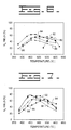
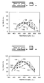
- Figs. 6 and 7 the effect of various doping levels of indium onto ⁇ -alumina prepared according to the present invention is shown.
- the metal doped ⁇ -alumina samples were prepared as described above.
- Fig. 6 the ability of the various samples to reduce NO to N 2 is shown.
- the samples were exposed to a stream of 0.1% NO, 0.1% C 3 H 6 , 9% O 2 , 7% H 2 O, the balance being He.
- reference number 80 represents a non-doped ⁇ -alumina prepared by the sol gel method;
- reference 82 represents a 1 weight percent indium doped ⁇ -alumina;
- reference 84 represents a 2.5 weight percent indium doped ⁇ -alumina;
- reference number 86 represents a 5 weight percent indium doped ⁇ -alumina; and
- reference 88 represents a 10 weight percent indium doped ⁇ -alumina.
- Fig. 7 the ability of the various samples to reduce NO 2 to N 2 is shown.
- the samples were exposed to a stream of 0.1% NO 2 , 0.1% C 3 H 6 , 9% O 2 , 7% H 2 O, the balance being He.
- reference number 90 represents the non-metal doped ⁇ -alumina
- reference number 92 represents the 1 weight percent indium doped ⁇ -alumina
- reference line 94 represents the 2.5 weight percent indium doped ⁇ -alumina
- reference 96 represents the 5 weight percent indium doped ⁇ -alumina
- reference 98 represents the 10 weight percent indium doped ⁇ -alumina.
- FIGs. 8 and 9 a similar comparison was done for tin doped ⁇ -alumina prepared according to the present invention.
- reference lines 100-112 represent, respectively, ⁇ -alumina; 1 weight percent tin doped ⁇ -alumina; 2.5 weight percent tin doped ⁇ -alumina; 5 weight percent tin doped ⁇ -alumina; 10 weight percent tin doped ⁇ -alumina; 15 weight percent tin doped ⁇ -alumina; and 20 weight percent tin doped ⁇ -alumina.
- reference lines 100-112 represent, respectively, ⁇ -alumina; 1 weight percent tin doped ⁇ -alumina; 2.5 weight percent tin doped ⁇ -alumina; 5 weight percent tin doped ⁇ -alumina; 10 weight percent tin doped ⁇ -alumina; 15 weight percent tin doped ⁇ -alumina; and 20 weight percent tin doped ⁇ -alumina.
- reference numbers 114-126 represent, respectively, ⁇ -alumina; 1 weight percent tin doped ⁇ -alumina; 2.5 weight percent tin doped ⁇ -alumina; 5 weight percent tin doped ⁇ -alumina; 10 weight percent tin doped ⁇ -alumina; 15 weight percent tin doped ⁇ -alumina; and 20 weight percent tin doped ⁇ -alumina.
- Fig. 8 the ability of the catalysts to reduce NO to N 2 is shown.
- Fig. 9 the ability of the catalysts to reduce NO 2 to N 2 is shown.
- the results demonstrate that all of the tin doped ⁇ -alumina catalysts show a lower Tmax and broader temperature window when compared to pure ⁇ -alumina. The best performing tin doped ⁇ -alumina was at approximately 10 weight percent.
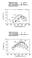
- Figs. 10 and 11 a similar comparison was done for gallium doped ⁇ -alumina prepared according to the present invention.
- Fig. 10 represents the reduction of NO to N 2 while
- Fig. 11 represents the reduction of NO 2 to N 2
- reference numbers 128-140 represent, respectively, non-metal doped ⁇ -alumina; 1 weight percent gallium doped ⁇ -alumina; 2.5 weight percent gallium doped ⁇ -alumina; 6 weight percent gallium doped ⁇ -alumina; 10 weight percent gallium doped ⁇ -alumina; 20 weight percent gallium doped ⁇ -alumina; and 24 weight percent gallium doped ⁇ -alumina.
- Fig. 10 represents the reduction of NO to N 2
- reference numbers 128-140 represent, respectively, non-metal doped ⁇ -alumina; 1 weight percent gallium doped ⁇ -alumina; 2.5 weight percent gallium doped ⁇ -alumina; 6 weight percent gallium doped ⁇ -alumina; 10 weight percent gallium doped ⁇ -alumina; 20
- 11 reference numbers 142-154 represent, respectively, non-metal doped ⁇ -alumina; 1 weight percent gallium doped ⁇ -alumina; 2.5 weight percent gallium doped ⁇ -alumina; 6 weight percent gallium doped ⁇ -alumina; 10 weight percent gallium doped ⁇ -alumina; 20 weight percent gallium doped ⁇ -alumina; and 24 weight percent gallium doped ⁇ -alumina.
- a 50 weight percent gallium doped ⁇ -alumina sample has been prepared. 50 weight percent gallium doped ⁇ -alumina shows the highest activity for NO or NO 2 reduction. All of the gallium doped ⁇ -alumina catalysts show better activity than the ⁇ -alumina catalyst alone and show a wider temperature window. All of the metal doped catalysts showed more NO x reduction when NO was replaced with NO 2 making these good catalysts for a PAC system.
- a simulated exhaust system was designed by coupling a non-thermal plasma in a tube to a catalytic unit in a standard two-stage setup to form a PAC system.
- the catalytic unit comprised a quartz tube that was packed with catalyst powder.
- the catalyst is held in place with quartz wool and fritted quartz disks.
- a 1 L/min gas flow was used in combination with 1 gram of catalyst powder. This results in a space velocity of 30,000 hr -1 depending on the powder used.
- the simulated oxygen rich exhaust was composed of 500 ppm NO, 300 ppm CO, 8% CO 2 , 1,5% H 2 O, 9% O 2 , 2000 ppm propene, plus or minus 20 ppm SO 2 , and the balance N 2 .
- Fig. 12 the data were obtained using a 2.5 weight % indium doped ⁇ -alumina prepared by the sol gel method are shown.
- the Y-axis is the percentage of the NO in the simulated exhaust that was converted to N 2 and the X-axis is the energy deposited by the non-thermal plasma.
- the results are shown for with or without SO 2 at tempertures of 200° C, 350° C, and 500° C.
- Reference lines 172 and 174 represent with and without SO 2 at 200° C, respectively.
- Reference lines 176 and 178 represent with and without SO 2 at 350° C, respectively.
- Reference lines 180 and 182 represent with and without SO 2 at 500° C, respectively.
- the catalytic activity of the indium doped ⁇ -alumina was reduced by the presence of the SO 2 .
- the coversion by the indium doped ⁇ -alumina was very high with or without SO 2 .
- the coversion in the absence of SO 2 was 90% while the coversion in the presence of SO 2 was 80%.
- Even in the presence of SO 2 the conversion was very high compared to other presently known lean NO x catalyst systems.
- the ⁇ -alumina In addition to the metals that have been disclosed above for doping of the ⁇ -alumina prepared by the sol gel method, other metals that could be utilized include silver, gold, copper, cobalt, iron, and cerium.
- the ⁇ -alumina preferably has a pore volume of from about 1.0 to about 2.0 cubic centimeters per gram, a surface area of greater than or equal to 200 meters squared per gram, and a sulfate level of less than or equal to 0.1%.
- the ⁇ -alumina is prepared by a sol gel method.
- the present invention is utilized for the treatment of oxygen rich exhaust.
- the present invention is utilized to remove nitrogen oxides from diesel engine exhaust.
- the diesel engine exhaust is passed through a non-thermal plasma generated by conventional means.
- additional hydrocarbons which can comprise diesel fuel itself.
- up to 95% of the nitrogen oxide in the oxygen rich exhaust is converted into nitrogen dioxide and the hydrocarbons are oxidized thereby forming an intermediate exhaust rich in nitrogen dioxide.
- the intermediate exhaust is passed over at least one metal doped ⁇ -alumina wherein the ⁇ -alumina has a pore size of greater than or equal to 1.0 cubic centimeter per gram.
- the metal doped ⁇ -alumina converts the nitrogen dioxide to N 2 .
- the present invention finds utilization as a method for treating any oxygen rich exhaust such as diesel or lean burn gasoline engine exhaust.
Landscapes
- Chemical & Material Sciences (AREA)
- Engineering & Computer Science (AREA)
- Combustion & Propulsion (AREA)
- Health & Medical Sciences (AREA)
- Biomedical Technology (AREA)
- Environmental & Geological Engineering (AREA)
- Analytical Chemistry (AREA)
- General Chemical & Material Sciences (AREA)
- Oil, Petroleum & Natural Gas (AREA)
- Chemical Kinetics & Catalysis (AREA)
- Catalysts (AREA)
- Exhaust Gas Treatment By Means Of Catalyst (AREA)
- Exhaust Gas After Treatment (AREA)
Abstract
The present disclosure pertains to a system
and method for treatment of oxygen rich exhaust and
more specifically to a method and system that combines
non-thermal plasma (26) with a metal doped γ-alumina catalyst,
wherein the γ-alumina has a pore volume of at least 1.0 cubic
centimeters per gram. It has been found that treatment of an oxygen
rich exhaust initially with a non-thermal plasma (26)
and followed by subsequent treatment with a metal
doped γ-alumina prepared by the sol gel method is
capable of increasing the NOx reduction to a level of
approximately 90% in the absence of SO2 and 80% in the
presence of 20ppm of SO2. Especially useful metals
have been found to be indium, gallium, and tin.
Description
- This invention relates generally to a system and method for treatment of lean exhaust, such as diesel exhaust and lean burn gasoline engine exhaust, to reduce nitrogen oxide (NO x ) emissions and more specifically to a method and system that combines non-thermal plasma with a metal doped γ-alumina catalyst for NO x reduction.
- The catalytic converters, especially three-way catalysts, used in combination with modern gasoline engines have resulted in a great reduction in tailpipe emissions of carbon monoxide, hydrocarbons and NO x . There is an increasing emphasis on fuel efficiency and diesel engines have an efficiency advantage over gasoline engines. Unfortunately, diesel engines are "lean burn" engines and their exhaust has very high levels of oxygen. These high levels of oxygen render gasoline catalytic converters useless for NO x reduction. Catalysts or catalytic systems that have been utilized for lean burn engines to date suffer from low removal of NO x , low thermal stability and a limited temperature window of operation. Most current catalytic systems for lean burn engines only achieve 7-12% NO x reduction as a passive system and 25-40% when supplemental hydrocarbon reductant is injected into the exhaust stream. Use of a non-thermal plasma system for reduction of NO x in conjunction with a particulate trap is disclosed in U.S. Patent No. 6,038,854 issued March 21, 2000 to Penetrante et al.
- The present invention is directed to overcome one or more of the problems as set forth above.
- In one aspect of this invention, there is disclosed a method for nitrogen oxide (NO x ) reduction in an oxygen rich engine exhaust comprising the steps of passing an oxygen rich exhaust through a non-thermal plasma thereby converting nitrogen oxide (NO) and hydrocarbons in the oxygen rich exhaust into nitrogen dioxide (NO2) and oxidized hydrocarbons and forming an intermediate exhaust; and then passing the intermediate exhaust over at least one metal doped γ-alumina, wherein the γ-alumina has been prepared with a pore volume of greater than 1.0 cubic centimeters per gram, thereby converting the NO2 to nitrogen (N2).
- In another aspect of the invention, it is an exhaust treatment system for nitrogen oxide reduction in lean burn engines comprising a non-thermal plasma in the exhaust system that is adapted to receive an oxygen rich exhaust, the non-thermal plasma converting the nitrogen oxide (NO) and hydrocarbons in the oxygen rich exhaust into nitrogen dioxide (NO2) and oxidized hydrocarbons, and a catalytic unit operably connected to the exhaust system and adapted to receive the oxygen rich exhaust after the non-thermal plasma, the catalytic unit comprising at least one metal doped γ-alumina, wherein the γ-alumina has a pore volume of at least 1.0 cubic centimeters per gram and the metal comprises indium, tin, gallium, silver, gold, copper, cobalt, iron, cerium, or mixtures thereof.
-
- Fig. 1 is a block diagram of a machine embodiment of the present invention.
- Fig. 2 shows the reduction of NO to N2 over various alumina samples.
- Fig. 3 shows the reduction of NO2 to N2 over the alumina samples used in Fig.2.
- Fig. 4 shows the reduction of NO to N2 over various catalyst samples.
- Fig. 5 shows the reduction of NO2 to N2 over the various catalyst samples of Fig. 4.
- Fig. 6 shows the reduction of NO to N2 over indium doped γ-alumina at various indium levels.
- Fig. 7 shows the reduction of NO2 to N2 over the indium doped γ-alumina samples of Fig. 6.
- Fig 8 shows the reduction of NO to N2 over tin doped γ-alumina at various tin levels.
- Fig. 9 shows the reduction of NO2 to N2 over the tin doped γ-alumina samples of Fig. 8.
- Fig 10 shows the reduction of NO to N2 over gallium doped γ-alumina at various gallium levels.
- Fig. 11 shows the reduction of NO2 to N2 over the gallium doped γ-alumina samples of Fig. 10.
- Fig. 12 shows the reduction of NO x to N2 in a plasma assisted catalytic system designed according to the present invention in the presence and absence of SO2.
-
- In Fig. 1 a block diagram of a machine embodiment of the present invention is shown generally at 10. A
fuel tank 20 delivers fuel to a "lean burn"engine 22. Throughout the specification and the claims a lean burn engine is defined as one that produces an oxygen rich exhaust, which is defined as an exhaust having a higher molar ratio of oxygen than the total molar ratio of reductive compounds such as CO, hydrogen and hydrocarbons. The exhausts have an oxidative environment. Examples of such engines include diesel engines and various lean burn gasoline engines. Generally, these systems generate an exhaust having an oxygen content of from 4 to 16 % depending on the load conditions and the running mode of the engine. An oxygen richexhaust exits engine 22 and is directed to pass through a non-thermalplasma 26. Preferably, this exhaust is supplemented, prior to treatment in the non-thermal plasma, by the addition of an atomized hydrocarbon or mixture ofhydrocarbons 24. One source of these hydrocarbons can be the diesel fuel from thefuel tank 20. Alternatively, as is known in the art, the supplemental hydrocarbon source can be other hydrocarbons other than the fuel. - Generation of a
non-thermal plasma 26 is well known in the art and will not be described in detail. In brief, a non-thermal plasma is created by connecting an alternating current voltage source to a pair of spaced apart electrodes having a dielectric barrier located in the space between them. In a typical system one of the electrodes is formed by a rod located in the center of an exhaust tube and the exhaust tube forms the other electrode. Preferably the alternating current voltage source generates a current of approximately 10 to 30 kilovolts. Because of the speed of the cycling of the alternating current voltage an electron and ionized gas cloud is created in the space between the two electrodes. The non-thermal plasma in the presence of oxygen and hydrocarbons will convert NO x into NO2 plus oxygenated hydrocarbons such as alcohols, aldehydes, and ketones. This generates an intermediate exhaust, which contains NO2, oxygenated hydrocarbons, unreacted hydrocarbons, and oxygen. In thenon-thermal plasma 26 up to 95% of the NO x is converted to NO2. - The intermediate exhaust is directed to a
catalytic unit 28. Deposited within the catalytic unit is a metal doped γ-alumina catalyst. The composition of this metal doped γ-alumina catalyst is described more fully below. In the catalytic unit 28 a substantial portion of the NO2 is converted to the reaction products of N2, carbon dioxide, and water. The conversion products leave the catalytic unit as a cleanedexhaust 30. - It has been found in the present invention that γ-alumina formed by a sol gel method produces an alumina having unique properties for utilization in plasma-assisted catalysis (PAC) of oxygen rich exhaust. The γ-alumina was prepared by a complexing agent-assisted sol gel method.
- In the sol gel method aluminum isopropoxide (AIP) (98+%, Aldrich Chemical Company, Inc.) was dissolved in 2-methyl-2,4-pentanediol (MPD) (99% Aldrich Chemical Company, Inc.). First, 500 g AIP was placed in a 2-liter glass beaker and then 600 milliliters of MPD was added immediately and the mixture was stirred vigorously with a mechanical polyethylene stirrer. Once the mixture was homogeneous, the beaker was placed in a constant temperature bath at a range of from 110 to 130°C and stirred continuously. After approximately 1 hour of stirring, all of the AIP was dissolved in the MPD. As the AIP reacts with the MPD, it produces 2-propanol which is released as a vapor at these temperatures. Gelation was completed after approximately 4 hours of reaction. Then 400 milliliters of water were added to stop the gelation and a white precipitate of aluminum hydroxide was obtained. The aluminum hydroxide solid was redispersed in water and aged at a temperature of from 60 to 90°C overnight with constant stirring.
- After aging overnight, 600 milliliters of 2-propanol was added to remove the water from the pores of the precipitate. Although 2-propanol is preferred, any organic solvent having a surface tension of approximately equal to or less than 30 mN/m will be useful. It is just necessary that the solvent have a surface tension significantly below that of water, which is approximately 72 mN/m. The resulting slurry was vacuum filtered and dried at approximately 90°C in an oven for 48 hours.
- Calcination was carried out in a temperature programmed tube furnace with 5 L/min air flowing through it. A general calcination schedule is as follows: ramp the temperature from 100°C to 460°C at 1°C/min with air flowing through it; ramp the temperature from 460°C to 700°C at 1°C/min with 2% H2O/air; 2 hours at 700°C with 6% H2O/air; and turn off the heat and continue flowing air over the alumina until the temperature is reduced to 100°C.
- This sol gel procedure resulted in γ-alumina (Al2O3) with a high surface area of approximately 200 to 230m2/g, a pore volume of from 1 to 2 cc/g, and a pore size of from 4 to 20 nm. Throughout the specification and claims the sol gel γ-alumina prepared according to the present invention was prepared as described above, the few exceptions are noted below.
- A metal doped γ-alumina prepared according to the present invention can be prepared in one of two ways. In one method, the subject metal is solubilized in the water that is used to stop gelation during the sol gel procedure described above. In a second method, the sol gel γ-alumina is doped with a metal by an incipient wetness method. In this method, the sol gel γ-alumina is brought into contact with a solution of the appropriate metal. The solution of the metal is present in an amount equal to or greater than the total pore volume of the γ-alumina sample. The pore volume of γ-alumina prepared according to the present invention is generally from 1.0 to 2.0 cubic centimeters per gram.
- To form a tin doped γ-alumina by the incipient wetness method an appropriate amount of SnCl2 was dissolved in an ethanol solution and brought into contact with the sol gel γ-alumina. The tin doped γ-alumina catalyst was calcined at 600°C for 5 hours and then at 800°C for 2 hours.
- An indium doped γ-alumina was prepared in the same manner using In(NO3)3 in a water solution instead of ethanol. The indium doped γ-alumina catalyst was calcined at 600°C for 5 hours.
- A gallium doped γ-alumina was prepared by exposing the γ-alumina to a water solution of Ga(NO3)3xH2O which was added to the aluminum oxide gel during the γ-alumina preparation in the sol gel method. The gallium doped γ-alumina catalyst was calcined at 600°C for 5 hours.
- Reactor bench tests to characterize the catalytic performance of various samples were performed in a quartz micro tube reactor with a feed gas of 0.1% NO x , 0.1% propene, 15% O2, and 10% H2O balanced with He. The flow rate was approximately 200 cc/min, and approximately 0.2 grams of catalyst was used. These conditions correspond to a space velocity of 30,000h-1. The reaction products were analyzed by a gas chromatograph equipped with a 6' molecular sieve and a 6' Porapak Q column. The NO x conversion was calculated from the amount of N2 produced. No N2O was detected in any of the experiments; thus, the N2 yield corresponded to the NOx conversion. The catalyst samples were pre-heated to 600°C in a flow of O2 and He. Then the samples were exposed to the oxygen rich simulated exhaust of 0.1% NO x , 0.1% propene, 15% O2, and 10% H2O balanced with He. In some experiments the level of oxygen varied, these changes are noted as appropriate below.
- The surface area, pore volume, and pore size distribution of various alumina samples were determined using a Micromeritics ASAP 2000 system. Approximately 0.2 to 2 grams of catalyst was out gassed under vacuum at 450°C overnight prior to adsorption measurements. The surface area was determined by multipoints measurement using several relative pressures of N2 to He in the range of 0.06 to 0.2 (N2 surface area 0.162 nm2) at 77 K.
- The level of the impurity sulfate (SO4) in various alumina samples was determined using ICP analysis. The ICP analysis was performed using a
Jobin Yvon 48 instrument. The alumina samples were completely digested in acid (HF) and diluted with deionized water. The acid solution was then injected into the plasma and the instrument scanned the sample for all the elements including sulfur. - The thermal stability of a γ-alumina prepared according to the above-referenced sol gel procedure was compared to various commercially available aluminas to determine whether its thermal stability were greater or less than these commercially available aluminas. To determine thermal stability surface area measurements for the various alumina samples were determined prior to and following hydrothermal aging tests. The aging test was performed in a 6" in diameter tube furnace set at 800°C for 15 hours with a 10% H2O/air flow at 5 liters per minute. The results of these tests are shown below in Table 1. The γ-alumina sample, prepared in accordance with the present invention, exhibited the highest surface area following the hydrothermal testing and showed one of the lowest reductions in surface area. The Alcoa HiQ7214F showed the lowest surface area change, but this is believed to be due to its lower initial surface area. Thus, the γ-alumina of the present invention is thermally more stable than a number of commercial aluminas.
Samples Before Aging (m2/g) After Aging (m2/g) Surface Area Change (%) Laroche (VGL-25) 280 146 48 W.R. Grace (MI-200) 237 126 47 Alcoa (DD447-165) 160 102 36 Alcoa (HiQ7214F) 146 118 19 γ-alumina 226 172 24 - Fig. 2 shows the NO reduction to N2 over the various alumina samples disclosed in Table 1 above. The samples were exposed to a stream of 0.1% NO, 0.1% propene, 15% O2, 10% H2O at 200 cc/min at the indicated temperatures. The Y-axis is the percent conversion of NO to N2 and the X-axis is the stream temperature.
Reference line 32 is the γ-alumina sample prepared by the sol gel method;reference line 34 is the Grace MI-200 sample; andreference line 36 is the Alcoa DD447-165 sample. From Fig. 2 it can be seen that the γ-alumina prepared by the sol gel method shows both a higher maximum NO conversion and a broader temperature window than the commercial aluminas. In addition, the γ-alumina sample showed higher NO conversion at lower temperatures. - In Fig. 3, the NO2 reduction to N2 over these same samples is shown. In this case the exposure was the same except that the NO was replaced with 0.1% NO2.
Reference line 38 represents the γ-alumina prepared by the sol gel method of the present invention;reference line 40 is the Grace MI-200 sample; andreference line 42 is the Aloca DD447-165 sample. As can be seen in Fig. 3, the γ-alumina also showed a higher NO2 conversion than the commercial aluminas. The γ-alumina also showed the lowest Tmax compared to the commercial aluminas. - The results shown in Figs. 2 and 3 indicate that the γ-alumina prepared by the sol gel method is more selective than commercial aluminas. By the term selective it is meant that the catalyst converts more NO x to N2 using less hydrocarbon. Also the γ-alumina converts NO2 to N2 to a higher extent than NO. This selectivity makes the sol gel γ-alumina particularly suitable for use in a PAC system.
- Various alumina samples were obtained from commercial suppliers and in addition the sol gel method of the present invention was modified to generate γ-aluminas having a range of pore volumes.
- The sample designated P091098 was prepared by the standard sol gel method with complexing agent as described above. Additional γ-aluminas according to the present invention were prepared with controlled pore structure without using a complexing agent. The procedure was to prepare a white slurry consisting of amorphous aluminum hydroxide by mixing aluminum isoproproxide with an excess of hot water at approximately 80°C under vigorous stirring conditions. One-third of the slurry was washed with water and this sample was designated as P012299. Another third of the slurry was washed with 2-propanol and designated as P012299a. Washing with 2-propanol provided a different surface tension on the γ-alumina during the drying step. Specifically because the surface tension of 2-propanol is smaller than water sample P012299a maintains its open pore structure resulting in a material containing a higher surface area, larger pore volume and larger average pore size compared to the water-washed sample (P012299). To the final third of the slurry a small amount of nitric acid was added for peptization of the aluminum hydroxide to a clear sol. The clear sol solution was subsequently mixed with 500 milliliters of water. The redispersed sol solution was aged overnight at approximately 85°C. A glassy crystalline material was obtained and designated P012299b. This sample exhibited the smallest pore volume and the smallest pore size.
- All of the γ-alumina samples prepared according to the present invention were dried at approximately 90°C overnight and calcined in a temperature-programmed furnace with a flowing air atmosphere. The furnace temperature was increased up to 700°C at a ramp rate of 1°C/min and held at 700°C for 2 hours.
- The surface area, pore volume, and average pore size of all the samples were measured using BET measurement as described above. The impurity level of SO4 was determined using ICP data as described above. Table 2 shows the results of the BET, ICP, and conversion of NO2 to N2 for the various alumina samples. In Table 2 the samples are ranked according to their percent yield of N2 from NO2. The top 8 samples have a sulfate impurity level of 0 with the exception of sample TA-1301E. This demonstrates the importance of reducing the sulfate impurity to obtain a catalytically active alumina. Of the top 8 aluminas shown in Table 2, the aluminas having larger pore volumes showed better NO2 reduction activity than aluminas having relatively smaller pore volumes. Among the top 3 aluminas shown in Table 2 the surface areas of these aluminas varied by a factor of 3, however the NO2 reduction performances of these aluminas were comparable. Thus, the surface area does not seem to affect the catalytic activity of the alumina.
- Based on these results it is preferred that any γ-alumina produced by any method used for the subject invention have a pore volume of from 1.0 to approximately 2.0 cubic centimeters per gram, and a sulfate impurity level of less than or equal to 0.1% sulfate. The surface area can vary, but it is preferable that it be equal to or greater than 200 m2/g. The γ-alumina can be prepared by any method such as precipitation in addition to the sol gel method so long as these physical characteristics are maintained. The results presented in Table 2 further reinforce the conclusion that the sol gel γ-alumina of the present invention is particularly suitable for use in a PAC system.
Rank Samples Surface Area (m2/g) Pore Volume (cc/g) Average Pore Size (nm) Impurity SO4 (%) N2 Yield from NO2 Reduction at 500°C (%) 1 P091098 230 1.1 14 0.0 60 2 P012299a 380 1.8 14 0.0 53 3 TA-1301E‡ 120 1.1 30 0.6 53 4 Catalox° 150 0.49 9 0.0 52 5 Puralox° 160 0.68 15 0.0 51 6 P012299b 240 0.28 4 0.0 49 7 Dispal° 80 0.62 27 0.0 42 8 P012299 250 0.42 5 0.0 41 9 MI-200 260 0.84 9 0.15 40 10 TA-2301E‡ 128 1.1 28 1.6 39 11 MI-307 HD 270 0.70 8 0.31 37 12 MI-207 350 1.2 10 0.72 32 13 MI-307 170 0.77 14 0.2 27 14 MI-120 280 0.92 10 0.7 27 15 BK-112L‡ 280 0.45 5 0.0 26 16 MI-407 160 0.72 14 0.16 26 17 BK-112‡ 320 0.2 3 0.0 23 18 MI-386 130 0.71 17 0.3 19 - In Fig. 4 metal doped γ-alumina samples prepared according to the present invention were compared to other known standard catalysts for their ability to reduce NO to N2. All the samples were exposed to a test gas of 0.1% NO, 0.1% propene, 9% O2, 7% H2O at 200 cc/min.
Reference line 44 shows the activity of a Pt/Fe ceria doped titanium silicalite catalyst.Reference line 46 shows the activity of a standard Cu-ZSM5 catalyst.Reference line 48 shows a γ-alumina sample prepared by the sol gel method of the present invention and doped with 2.5 weight percent indium.Reference line 50 shows the activity of a γ-alumina sample prepared by the sol gel method of the present invention doped with 24 weight percent gallium. As can be seen from Fig. 4 metal doped γ-alumina catalysts prepared according to the present invention are much more effective in reduction of NO than are either Pt or Cu-ZSM5 catalysts in reducing NO. Also the Pt catalyst produces a substantial amount of N2O, which is a greenhouse gas. - In Fig. 5 the same samples as in Fig. 4 are shown for their ability to reduce NO2. to N2. The reference lines 52-58 are, respectively, the Pt/Fe ceria doped titanium silicalite catalyst, Cu-ZSM5 catalyst, 2.5 weight % indium doped γ-alumina, and 24 weight % gallium doped γ-alumina. All the conditions are the same as for Fig. 4 except that the feed gas include 0.1% NO2 instead of NO. Again, it can be seen that metal doped γ-alumina catalysts prepared according to the present invention yield more N2 than either Pt or Cu-ZSM5 catalysts. This selectivity makes the metal doped sol gel γ-alumina particularly suitable for use in a PAC system.
- In Figs. 6 and 7, the effect of various doping levels of indium onto γ-alumina prepared according to the present invention is shown. The metal doped γ-alumina samples were prepared as described above.
- In Fig. 6 the ability of the various samples to reduce NO to N2 is shown. The samples were exposed to a stream of 0.1% NO, 0.1% C3H6, 9% O2, 7% H2O, the balance being He. In Fig. 6,
reference number 80 represents a non-doped γ-alumina prepared by the sol gel method;reference 82 represents a 1 weight percent indium doped γ-alumina;reference 84 represents a 2.5 weight percent indium doped γ-alumina;reference number 86 represents a 5 weight percent indium doped γ-alumina; andreference 88 represents a 10 weight percent indium doped γ-alumina. - In Fig. 7 the ability of the various samples to reduce NO2 to N2 is shown. The samples were exposed to a stream of 0.1% NO2, 0.1% C3H6, 9% O2, 7% H2O, the balance being He. In Fig. 7,
reference number 90 represents the non-metal doped γ-alumina;reference number 92 represents the 1 weight percent indium doped γ-alumina;reference line 94 represents the 2.5 weight percent indium doped γ-alumina;reference 96 represents the 5 weight percent indium doped γ-alumina; andreference 98 represents the 10 weight percent indium doped γ-alumina. - It can be seen from Figs. 6 and 7 that maximal activity was achieved with an indium level of approximately 2.5 weight percent. Furthermore, it can be seen that the indium doped γ-alumina catalyst showed a lower Tmax and exhibited a broader temperature window than the pure γ-alumina itself.
- In Figs. 8 and 9, a similar comparison was done for tin doped γ-alumina prepared according to the present invention. In Fig. 8, reference lines 100-112 represent, respectively, γ-alumina; 1 weight percent tin doped γ-alumina; 2.5 weight percent tin doped γ-alumina; 5 weight percent tin doped γ-alumina; 10 weight percent tin doped γ-alumina; 15 weight percent tin doped γ-alumina; and 20 weight percent tin doped γ-alumina. In Fig. 9, reference numbers 114-126 represent, respectively, γ-alumina; 1 weight percent tin doped γ-alumina; 2.5 weight percent tin doped γ-alumina; 5 weight percent tin doped γ-alumina; 10 weight percent tin doped γ-alumina; 15 weight percent tin doped γ-alumina; and 20 weight percent tin doped γ-alumina. In Fig. 8 the ability of the catalysts to reduce NO to N2 is shown. In Fig. 9 the ability of the catalysts to reduce NO2 to N2 is shown. The results demonstrate that all of the tin doped γ-alumina catalysts show a lower Tmax and broader temperature window when compared to pure γ-alumina. The best performing tin doped γ-alumina was at approximately 10 weight percent.
- In Figs. 10 and 11, a similar comparison was done for gallium doped γ-alumina prepared according to the present invention. Fig. 10 represents the reduction of NO to N2 while Fig. 11 represents the reduction of NO2 to N2 In Fig. 10, reference numbers 128-140 represent, respectively, non-metal doped γ-alumina; 1 weight percent gallium doped γ-alumina; 2.5 weight percent gallium doped γ-alumina; 6 weight percent gallium doped γ-alumina; 10 weight percent gallium doped γ-alumina; 20 weight percent gallium doped γ-alumina; and 24 weight percent gallium doped γ-alumina. In Fig. 11 reference numbers 142-154 represent, respectively, non-metal doped γ-alumina; 1 weight percent gallium doped γ-alumina; 2.5 weight percent gallium doped γ-alumina; 6 weight percent gallium doped γ-alumina; 10 weight percent gallium doped γ-alumina; 20 weight percent gallium doped γ-alumina; and 24 weight percent gallium doped γ-alumina. In addition to the samples shown in Figs. 10 and 11, a 50 weight percent gallium doped γ-alumina sample has been prepared. 50 weight percent gallium doped γ-alumina shows the highest activity for NO or NO2 reduction. All of the gallium doped γ-alumina catalysts show better activity than the γ-alumina catalyst alone and show a wider temperature window. All of the metal doped catalysts showed more NO x reduction when NO was replaced with NO2 making these good catalysts for a PAC system.
- To assess the impact of a non-thermal plasma on metal doped γ-alumina catalysts prepared according to the present invention, a simulated exhaust system was designed by coupling a non-thermal plasma in a tube to a catalytic unit in a standard two-stage setup to form a PAC system. The catalytic unit comprised a quartz tube that was packed with catalyst powder. The catalyst is held in place with quartz wool and fritted quartz disks. A 1 L/min gas flow was used in combination with 1 gram of catalyst powder. This results in a space velocity of 30,000 hr-1 depending on the powder used. The simulated oxygen rich exhaust was composed of 500 ppm NO, 300 ppm CO, 8% CO2, 1,5% H2O, 9% O2, 2000 ppm propene, plus or minus 20 ppm SO2, and the balance N2.
- In Fig. 12 the data were obtained using a 2.5 weight % indium doped γ-alumina prepared by the sol gel method are shown. In Fig. 12 the Y-axis is the percentage of the NO in the simulated exhaust that was converted to N2 and the X-axis is the energy deposited by the non-thermal plasma. The results are shown for with or without SO2 at tempertures of 200° C, 350° C, and 500°
C. Reference lines 172 and 174 represent with and without SO2 at 200° C, respectively.Reference lines 176 and 178 represent with and without SO2 at 350° C, respectively.Reference lines 180 and 182 represent with and without SO2 at 500° C, respectively. The catalytic activity of the indium doped γ-alumina was reduced by the presence of the SO2. At tempertures near that of normal exhaust, between 350° C and 500° C, the coversion by the indium doped γ-alumina was very high with or without SO2. At a temperature of 500° C the coversion in the absence of SO2 was 90% while the coversion in the presence of SO2 was 80%. Even in the presence of SO2 the conversion was very high compared to other presently known lean NO x catalyst systems. - In addition to the metals that have been disclosed above for doping of the γ-alumina prepared by the sol gel method, other metals that could be utilized include silver, gold, copper, cobalt, iron, and cerium. In practicing the present invention the γ-alumina preferably has a pore volume of from about 1.0 to about 2.0 cubic centimeters per gram, a surface area of greater than or equal to 200 meters squared per gram, and a sulfate level of less than or equal to 0.1%. In a preferred embodiment the γ-alumina is prepared by a sol gel method.
- Of course, various modifications of this invention would come within the scope of the invention.
- The present invention is utilized for the treatment of oxygen rich exhaust. In one use, the present invention is utilized to remove nitrogen oxides from diesel engine exhaust. In a first step the diesel engine exhaust is passed through a non-thermal plasma generated by conventional means. Prior to passing through the non-thermal plasma preferably the diesel exhaust is supplemented with additional hydrocarbons, which can comprise diesel fuel itself. In this first step, up to 95% of the nitrogen oxide in the oxygen rich exhaust is converted into nitrogen dioxide and the hydrocarbons are oxidized thereby forming an intermediate exhaust rich in nitrogen dioxide. The intermediate exhaust is passed over at least one metal doped γ-alumina wherein the γ-alumina has a pore size of greater than or equal to 1.0 cubic centimeter per gram. The metal doped γ-alumina converts the nitrogen dioxide to N2. The present invention finds utilization as a method for treating any oxygen rich exhaust such as diesel or lean burn gasoline engine exhaust.
- Other aspects, objects and advantages of this invention can be obtained from a study of the drawings, the disclosure and the appended claims.
Claims (4)
- A method for nitrogen oxide (NO x ) reduction in an oxygen rich engine exhaust comprising the steps of:a) passing an oxygen rich exhaust through a non-thermal plasma (26) thereby converting nitrogen oxide (NO) and hydrocarbons in the oxygen rich exhaust into nitrogen dioxide (NO2) and oxidized hydrocarbons and forming an intermediate exhaust;b) passing the intermediate exhaust over at least one metal doped γ-alumina, wherein the γ-alumina has a pore volume of at least 1.0 cubic centimeters per gram, thereby converting the NO2 to nitrogen (N2).
- A method as claimed in Claim 1, wherein step a) comprises the further step of injecting an amount of at least one atomized hydrocarbon (24) into the oxygen rich exhaust prior to passing the oxygen rich exhaust through the non-thermal plasma (26).
- A method as recited in Claim 1, wherein step a) further comprises passing an oxygen rich exhaust having an oxygen content of equal to or greater than 4% through the non-thermal plasma (26).
- A method as recited in Claim 1, wherein step b) further comprises a step of selecting the metal for doping of the γ-alumina from the group
Applications Claiming Priority (2)
| Application Number | Priority Date | Filing Date | Title |
|---|---|---|---|
| US09/708,863 US7081231B1 (en) | 2000-11-08 | 2000-11-08 | Method and system for the combination of non-thermal plasma and metal/metal oxide doped γ-alumina catalysts for diesel engine exhaust aftertreatment system |
| US708863 | 2000-11-08 |
Publications (1)
| Publication Number | Publication Date |
|---|---|
| EP1205235A1 true EP1205235A1 (en) | 2002-05-15 |
Family
ID=24847464
Family Applications (1)
| Application Number | Title | Priority Date | Filing Date |
|---|---|---|---|
| EP01118587A Withdrawn EP1205235A1 (en) | 2000-11-08 | 2001-08-02 | Method and system for diesel engine exhaust treatment using a combination of non-thermal plasma and metal doped gamma-alumina catalysts |
Country Status (4)
| Country | Link |
|---|---|
| US (1) | US7081231B1 (en) |
| EP (1) | EP1205235A1 (en) |
| JP (1) | JP2002191940A (en) |
| CA (1) | CA2354207C (en) |
Cited By (3)
| Publication number | Priority date | Publication date | Assignee | Title |
|---|---|---|---|---|
| US7399729B2 (en) | 2003-12-22 | 2008-07-15 | General Electric Company | Catalyst system for the reduction of NOx |
| WO2011090463A1 (en) * | 2009-12-29 | 2011-07-28 | Dow Global Technologies Inc. | Catalytic composition for production of alpha-olefins |
| AU2020286326B2 (en) * | 2019-12-11 | 2022-02-17 | A & J Australia Pty Ltd | Multi-hold container |
Families Citing this family (20)
| Publication number | Priority date | Publication date | Assignee | Title |
|---|---|---|---|---|
| US7541010B2 (en) * | 2003-12-19 | 2009-06-02 | Caterpillar Inc. | Silver doped catalysts for treatment of exhaust |
| US20050135977A1 (en) * | 2003-12-19 | 2005-06-23 | Caterpillar Inc. | Multi-part catalyst system for exhaust treatment elements |
| US8871669B2 (en) * | 2008-05-19 | 2014-10-28 | General Electric Company | Catalyst and method of manufacture |
| US20110047995A1 (en) * | 2009-08-31 | 2011-03-03 | General Electric Company | Catalyst and method of manufacture |
| US20090263297A1 (en) * | 2007-09-19 | 2009-10-22 | General Electric Company | Catalyst and method of manufacture |
| US9272271B2 (en) | 2007-09-19 | 2016-03-01 | General Electric Company | Manufacture of catalyst compositions and systems |
| US9375710B2 (en) | 2007-09-19 | 2016-06-28 | General Electric Company | Catalyst and method of manufacture |
| EP2161070B1 (en) * | 2008-09-04 | 2013-11-27 | Haldor Topsoe A/S | Process and catalyst system for NOx reduction |
| US20100196237A1 (en) * | 2009-01-30 | 2010-08-05 | General Electric Company | Templated catalyst composition and associated method |
| US20100196236A1 (en) * | 2009-01-30 | 2010-08-05 | General Electric Company | Templated catalyst composition and associated method |
| RU2403955C1 (en) * | 2009-05-28 | 2010-11-20 | Федеральное государственное унитарное предприятие "Московское машиностроительное производственное предприятие "САЛЮТ" (ФГУП "ММПП "САЛЮТ") | Method of cleaning gas emissions of nitrogen oxides |
| US8889587B2 (en) | 2009-08-31 | 2014-11-18 | General Electric Company | Catalyst and method of manufacture |
| US20110209466A1 (en) * | 2010-02-26 | 2011-09-01 | General Electric Company | Catalyst composition and catalytic reduction system comprising yttrium |
| US8987161B2 (en) | 2010-08-13 | 2015-03-24 | Ut-Battelle, Llc | Zeolite-based SCR catalysts and their use in diesel engine emission treatment |
| US8586501B2 (en) | 2010-10-04 | 2013-11-19 | General Electric Company | Catalyst and method of manufacture |
| US8505285B2 (en) | 2010-10-06 | 2013-08-13 | General Electric Company | Catalyst and method of manufacture |
| US20120329644A1 (en) | 2011-06-21 | 2012-12-27 | General Electric Company | Catalyst composition and catalytic reduction system |
| GB201421663D0 (en) * | 2014-12-05 | 2015-01-21 | Luxfer Canada Ltd | Gas cylinder valve |
| RU2689020C1 (en) | 2018-10-30 | 2019-05-23 | Радченко Виталий Анатольевич | Device for the internal combustion engines emissions cleaning of the nitrogen oxides using the non-equilibrium low-temperature plasma and the absorber |
| CN114229892B (en) * | 2021-12-23 | 2023-10-13 | 株洲科能新材料股份有限公司 | Ion implantation doped bismuth oxide and preparation method and application thereof |
Citations (3)
| Publication number | Priority date | Publication date | Assignee | Title |
|---|---|---|---|---|
| US5711147A (en) * | 1996-08-19 | 1998-01-27 | The Regents Of The University Of California | Plasma-assisted catalytic reduction system |
| DE19820682A1 (en) * | 1997-05-16 | 1998-11-19 | Siemens Ag | Eliminating oxidic pollutants in diesel engine exhaust gas |
| WO2001076733A1 (en) * | 2000-04-11 | 2001-10-18 | Accentus Plc | The plasma assisted catalytic treatment of gases |
Family Cites Families (7)
| Publication number | Priority date | Publication date | Assignee | Title |
|---|---|---|---|---|
| US6232253B1 (en) * | 1994-09-23 | 2001-05-15 | Ford Global Technologies, Inc. | Sol-gel alumina membrane for lean NOx catalysts and method of making same |
| US5609736A (en) | 1995-09-26 | 1997-03-11 | Research Triangle Institute | Methods and apparatus for controlling toxic compounds using catalysis-assisted non-thermal plasma |
| US5746984A (en) | 1996-06-28 | 1998-05-05 | Low Emissions Technologies Research And Development Partnership | Exhaust system with emissions storage device and plasma reactor |
| US6038854A (en) | 1996-08-19 | 2000-03-21 | The Regents Of The University Of California | Plasma regenerated particulate trap and NOx reduction system |
| US5891409A (en) | 1996-08-19 | 1999-04-06 | The Regents Of The University Of California | Pre-converted nitric oxide gas in catalytic reduction system |
| US6038853A (en) | 1996-08-19 | 2000-03-21 | The Regents Of The University Of California | Plasma-assisted catalytic storage reduction system |
| US6592833B1 (en) * | 1999-10-18 | 2003-07-15 | Delphi Technologies, Inc. | Method of NOx abatement in high temperature lean NOx catalyst systems |
-
2000
- 2000-11-08 US US09/708,863 patent/US7081231B1/en not_active Expired - Fee Related
-
2001
- 2001-07-26 CA CA002354207A patent/CA2354207C/en not_active Expired - Fee Related
- 2001-08-02 EP EP01118587A patent/EP1205235A1/en not_active Withdrawn
- 2001-09-28 JP JP2001300972A patent/JP2002191940A/en not_active Withdrawn
Patent Citations (3)
| Publication number | Priority date | Publication date | Assignee | Title |
|---|---|---|---|---|
| US5711147A (en) * | 1996-08-19 | 1998-01-27 | The Regents Of The University Of California | Plasma-assisted catalytic reduction system |
| DE19820682A1 (en) * | 1997-05-16 | 1998-11-19 | Siemens Ag | Eliminating oxidic pollutants in diesel engine exhaust gas |
| WO2001076733A1 (en) * | 2000-04-11 | 2001-10-18 | Accentus Plc | The plasma assisted catalytic treatment of gases |
Cited By (4)
| Publication number | Priority date | Publication date | Assignee | Title |
|---|---|---|---|---|
| US7399729B2 (en) | 2003-12-22 | 2008-07-15 | General Electric Company | Catalyst system for the reduction of NOx |
| WO2011090463A1 (en) * | 2009-12-29 | 2011-07-28 | Dow Global Technologies Inc. | Catalytic composition for production of alpha-olefins |
| US8962904B2 (en) | 2009-12-29 | 2015-02-24 | Dow Global Technologies Llc | Catalytic composition for production of alpha-olefins |
| AU2020286326B2 (en) * | 2019-12-11 | 2022-02-17 | A & J Australia Pty Ltd | Multi-hold container |
Also Published As
| Publication number | Publication date |
|---|---|
| CA2354207C (en) | 2009-05-05 |
| JP2002191940A (en) | 2002-07-10 |
| CA2354207A1 (en) | 2002-05-08 |
| US7081231B1 (en) | 2006-07-25 |
Similar Documents
| Publication | Publication Date | Title |
|---|---|---|
| US7081231B1 (en) | Method and system for the combination of non-thermal plasma and metal/metal oxide doped γ-alumina catalysts for diesel engine exhaust aftertreatment system | |
| US6706660B2 (en) | Metal/metal oxide doped oxide catalysts having high deNOx selectivity for lean NOx exhaust aftertreatment systems | |
| US6703343B2 (en) | Method of preparing doped oxide catalysts for lean NOx exhaust | |
| Ding et al. | Promotional effect of Nb additive on the activity and hydrothermal stability for the selective catalytic reduction of NOx with NH3 over CeZrOx catalyst | |
| KR102580600B1 (en) | Cerium- and zirconium-based mixed oxides | |
| KR101165499B1 (en) | Highly acidic composition containing zirconium oxide, titanium oxide and tungsten oxide, method for preparing the same and use thereof in the treatment of exhaust gases | |
| JP5094717B2 (en) | Method and apparatus for combining catalysts for reducing NOx in combustion products | |
| KR970009558B1 (en) | Copper oxide and ceria catalyst | |
| US20160166988A1 (en) | Highly acidic compositions comprising zirconium and silicon oxides and an oxide of at least one other element selected from among titanium, aluminum, tungsten, molybdenum, cerium, iron, tin, zinc, and manganese | |
| CA2057634A1 (en) | Catalyst for purification of exhaust gases | |
| RU2635092C2 (en) | Catalytic composition | |
| CN113559850A (en) | Manganese-based composite oxide catalyst and preparation method and use thereof | |
| KR20080027720A (en) | Gas purification method, gas purification device and gas purification catalyst | |
| Shao et al. | Promotion effects of cesium on perovskite oxides for catalytic soot combustion | |
| CN101506481B (en) | Selective catalyst reduction of nitrogen oxides with hydrogen | |
| Zhengling et al. | CuW/CeZr catalysts: a dual-function catalyst for selective catalytic reduction of NO and CO oxidation under oxygen-rich conditions | |
| Zhang et al. | CeO2-ZrO2-La2O3-Al2O3 composite oxide and its supported palladium catalyst for the treatment of exhaust of natural gas engined vehicles | |
| Pruvost et al. | Effect of copper addition on the activity and selectivity of oxide catalysts in the combustion of carbon particulate | |
| CN116078423B (en) | In/H-Beta@CeO2 catalyst and its preparation method and application | |
| JP4974674B2 (en) | Complex oxide | |
| Lu et al. | Effect of Mg/Al molar ratios on NO reduction activity of CO using Ce-La/MgAl2O4-x catalysts | |
| Haneda et al. | Additive Effect of Silver on the Catalytic Activity of TiO2–ZrO2 for the Selective Reduction of NO with Propene, 2-Propanol, and Acetone | |
| CN106621807B (en) | Flue gas treatment method for catalytic reduction, desulfurization and denitrification of titanium dioxide nanotube array loaded with lanthanum-cerium oxide | |
| Bian et al. | The SCR reaction and mechanism of a silicic acid modified Ce-W/TiO 2 catalyst | |
| Jeon et al. | Selective catalytic reduction of NOx in lean-burn engine exhaust over a Pt/V/MCM-41 catalyst |
Legal Events
| Date | Code | Title | Description |
|---|---|---|---|
| PUAI | Public reference made under article 153(3) epc to a published international application that has entered the european phase |
Free format text: ORIGINAL CODE: 0009012 |
|
| AK | Designated contracting states |
Kind code of ref document: A1 Designated state(s): AT BE CH CY DE DK ES FI FR GB GR IE IT LI LU MC NL PT SE TR |
|
| AX | Request for extension of the european patent |
Free format text: AL;LT;LV;MK;RO;SI |
|
| AKX | Designation fees paid |
Designated state(s): DE FR GB |
|
| STAA | Information on the status of an ep patent application or granted ep patent |
Free format text: STATUS: THE APPLICATION IS DEEMED TO BE WITHDRAWN |
|
| 18D | Application deemed to be withdrawn |
Effective date: 20021116 |