EP1205161A2 - Self-locking modular prosthesis having taper feature and associated method - Google Patents
Self-locking modular prosthesis having taper feature and associated method Download PDFInfo
- Publication number
- EP1205161A2 EP1205161A2 EP01309464A EP01309464A EP1205161A2 EP 1205161 A2 EP1205161 A2 EP 1205161A2 EP 01309464 A EP01309464 A EP 01309464A EP 01309464 A EP01309464 A EP 01309464A EP 1205161 A2 EP1205161 A2 EP 1205161A2
- Authority
- EP
- European Patent Office
- Prior art keywords
- post
- elongated bore
- tapered
- component
- threaded aperture
- Prior art date
- Legal status (The legal status is an assumption and is not a legal conclusion. Google has not performed a legal analysis and makes no representation as to the accuracy of the status listed.)
- Granted
Links
Images


Classifications
-
- A—HUMAN NECESSITIES
- A61—MEDICAL OR VETERINARY SCIENCE; HYGIENE
- A61F—FILTERS IMPLANTABLE INTO BLOOD VESSELS; PROSTHESES; DEVICES PROVIDING PATENCY TO, OR PREVENTING COLLAPSING OF, TUBULAR STRUCTURES OF THE BODY, e.g. STENTS; ORTHOPAEDIC, NURSING OR CONTRACEPTIVE DEVICES; FOMENTATION; TREATMENT OR PROTECTION OF EYES OR EARS; BANDAGES, DRESSINGS OR ABSORBENT PADS; FIRST-AID KITS
- A61F2/00—Filters implantable into blood vessels; Prostheses, i.e. artificial substitutes or replacements for parts of the body; Appliances for connecting them with the body; Devices providing patency to, or preventing collapsing of, tubular structures of the body, e.g. stents
- A61F2/02—Prostheses implantable into the body
- A61F2/30—Joints
- A61F2/30721—Accessories
- A61F2/30734—Modular inserts, sleeves or augments, e.g. placed on proximal part of stem for fixation purposes or wedges for bridging a bone defect
-
- A—HUMAN NECESSITIES
- A61—MEDICAL OR VETERINARY SCIENCE; HYGIENE
- A61F—FILTERS IMPLANTABLE INTO BLOOD VESSELS; PROSTHESES; DEVICES PROVIDING PATENCY TO, OR PREVENTING COLLAPSING OF, TUBULAR STRUCTURES OF THE BODY, e.g. STENTS; ORTHOPAEDIC, NURSING OR CONTRACEPTIVE DEVICES; FOMENTATION; TREATMENT OR PROTECTION OF EYES OR EARS; BANDAGES, DRESSINGS OR ABSORBENT PADS; FIRST-AID KITS
- A61F2/00—Filters implantable into blood vessels; Prostheses, i.e. artificial substitutes or replacements for parts of the body; Appliances for connecting them with the body; Devices providing patency to, or preventing collapsing of, tubular structures of the body, e.g. stents
- A61F2/02—Prostheses implantable into the body
- A61F2/30—Joints
- A61F2/32—Joints for the hip
- A61F2/36—Femoral heads ; Femoral endoprostheses
-
- A—HUMAN NECESSITIES
- A61—MEDICAL OR VETERINARY SCIENCE; HYGIENE
- A61F—FILTERS IMPLANTABLE INTO BLOOD VESSELS; PROSTHESES; DEVICES PROVIDING PATENCY TO, OR PREVENTING COLLAPSING OF, TUBULAR STRUCTURES OF THE BODY, e.g. STENTS; ORTHOPAEDIC, NURSING OR CONTRACEPTIVE DEVICES; FOMENTATION; TREATMENT OR PROTECTION OF EYES OR EARS; BANDAGES, DRESSINGS OR ABSORBENT PADS; FIRST-AID KITS
- A61F2/00—Filters implantable into blood vessels; Prostheses, i.e. artificial substitutes or replacements for parts of the body; Appliances for connecting them with the body; Devices providing patency to, or preventing collapsing of, tubular structures of the body, e.g. stents
- A61F2/02—Prostheses implantable into the body
- A61F2/30—Joints
- A61F2/46—Special tools or methods for implanting or extracting artificial joints, accessories, bone grafts or substitutes, or particular adaptations therefor
- A61F2/4603—Special tools or methods for implanting or extracting artificial joints, accessories, bone grafts or substitutes, or particular adaptations therefor for insertion or extraction of endoprosthetic joints or of accessories thereof
- A61F2/4607—Special tools or methods for implanting or extracting artificial joints, accessories, bone grafts or substitutes, or particular adaptations therefor for insertion or extraction of endoprosthetic joints or of accessories thereof of hip femoral endoprostheses
-
- A—HUMAN NECESSITIES
- A61—MEDICAL OR VETERINARY SCIENCE; HYGIENE
- A61F—FILTERS IMPLANTABLE INTO BLOOD VESSELS; PROSTHESES; DEVICES PROVIDING PATENCY TO, OR PREVENTING COLLAPSING OF, TUBULAR STRUCTURES OF THE BODY, e.g. STENTS; ORTHOPAEDIC, NURSING OR CONTRACEPTIVE DEVICES; FOMENTATION; TREATMENT OR PROTECTION OF EYES OR EARS; BANDAGES, DRESSINGS OR ABSORBENT PADS; FIRST-AID KITS
- A61F2/00—Filters implantable into blood vessels; Prostheses, i.e. artificial substitutes or replacements for parts of the body; Appliances for connecting them with the body; Devices providing patency to, or preventing collapsing of, tubular structures of the body, e.g. stents
- A61F2/02—Prostheses implantable into the body
- A61F2/30—Joints
- A61F2/30767—Special external or bone-contacting surface, e.g. coating for improving bone ingrowth
- A61F2/30771—Special external or bone-contacting surface, e.g. coating for improving bone ingrowth applied in original prostheses, e.g. holes or grooves
-
- A—HUMAN NECESSITIES
- A61—MEDICAL OR VETERINARY SCIENCE; HYGIENE
- A61F—FILTERS IMPLANTABLE INTO BLOOD VESSELS; PROSTHESES; DEVICES PROVIDING PATENCY TO, OR PREVENTING COLLAPSING OF, TUBULAR STRUCTURES OF THE BODY, e.g. STENTS; ORTHOPAEDIC, NURSING OR CONTRACEPTIVE DEVICES; FOMENTATION; TREATMENT OR PROTECTION OF EYES OR EARS; BANDAGES, DRESSINGS OR ABSORBENT PADS; FIRST-AID KITS
- A61F2/00—Filters implantable into blood vessels; Prostheses, i.e. artificial substitutes or replacements for parts of the body; Appliances for connecting them with the body; Devices providing patency to, or preventing collapsing of, tubular structures of the body, e.g. stents
- A61F2/02—Prostheses implantable into the body
- A61F2/30—Joints
- A61F2/32—Joints for the hip
- A61F2/36—Femoral heads ; Femoral endoprostheses
- A61F2/3662—Femoral shafts
- A61F2/367—Proximal or metaphyseal parts of shafts
-
- A—HUMAN NECESSITIES
- A61—MEDICAL OR VETERINARY SCIENCE; HYGIENE
- A61F—FILTERS IMPLANTABLE INTO BLOOD VESSELS; PROSTHESES; DEVICES PROVIDING PATENCY TO, OR PREVENTING COLLAPSING OF, TUBULAR STRUCTURES OF THE BODY, e.g. STENTS; ORTHOPAEDIC, NURSING OR CONTRACEPTIVE DEVICES; FOMENTATION; TREATMENT OR PROTECTION OF EYES OR EARS; BANDAGES, DRESSINGS OR ABSORBENT PADS; FIRST-AID KITS
- A61F2/00—Filters implantable into blood vessels; Prostheses, i.e. artificial substitutes or replacements for parts of the body; Appliances for connecting them with the body; Devices providing patency to, or preventing collapsing of, tubular structures of the body, e.g. stents
- A61F2/02—Prostheses implantable into the body
- A61F2/30—Joints
- A61F2/32—Joints for the hip
- A61F2/36—Femoral heads ; Femoral endoprostheses
- A61F2/3662—Femoral shafts
- A61F2/3676—Distal or diaphyseal parts of shafts
-
- A—HUMAN NECESSITIES
- A61—MEDICAL OR VETERINARY SCIENCE; HYGIENE
- A61F—FILTERS IMPLANTABLE INTO BLOOD VESSELS; PROSTHESES; DEVICES PROVIDING PATENCY TO, OR PREVENTING COLLAPSING OF, TUBULAR STRUCTURES OF THE BODY, e.g. STENTS; ORTHOPAEDIC, NURSING OR CONTRACEPTIVE DEVICES; FOMENTATION; TREATMENT OR PROTECTION OF EYES OR EARS; BANDAGES, DRESSINGS OR ABSORBENT PADS; FIRST-AID KITS
- A61F2/00—Filters implantable into blood vessels; Prostheses, i.e. artificial substitutes or replacements for parts of the body; Appliances for connecting them with the body; Devices providing patency to, or preventing collapsing of, tubular structures of the body, e.g. stents
- A61F2/02—Prostheses implantable into the body
- A61F2/30—Joints
- A61F2/46—Special tools or methods for implanting or extracting artificial joints, accessories, bone grafts or substitutes, or particular adaptations therefor
- A61F2/4603—Special tools or methods for implanting or extracting artificial joints, accessories, bone grafts or substitutes, or particular adaptations therefor for insertion or extraction of endoprosthetic joints or of accessories thereof
-
- A—HUMAN NECESSITIES
- A61—MEDICAL OR VETERINARY SCIENCE; HYGIENE
- A61F—FILTERS IMPLANTABLE INTO BLOOD VESSELS; PROSTHESES; DEVICES PROVIDING PATENCY TO, OR PREVENTING COLLAPSING OF, TUBULAR STRUCTURES OF THE BODY, e.g. STENTS; ORTHOPAEDIC, NURSING OR CONTRACEPTIVE DEVICES; FOMENTATION; TREATMENT OR PROTECTION OF EYES OR EARS; BANDAGES, DRESSINGS OR ABSORBENT PADS; FIRST-AID KITS
- A61F2/00—Filters implantable into blood vessels; Prostheses, i.e. artificial substitutes or replacements for parts of the body; Appliances for connecting them with the body; Devices providing patency to, or preventing collapsing of, tubular structures of the body, e.g. stents
- A61F2/02—Prostheses implantable into the body
- A61F2/30—Joints
- A61F2002/30001—Additional features of subject-matter classified in A61F2/28, A61F2/30 and subgroups thereof
- A61F2002/30316—The prosthesis having different structural features at different locations within the same prosthesis; Connections between prosthetic parts; Special structural features of bone or joint prostheses not otherwise provided for
- A61F2002/30317—The prosthesis having different structural features at different locations within the same prosthesis
- A61F2002/30322—The prosthesis having different structural features at different locations within the same prosthesis differing in surface structures
-
- A—HUMAN NECESSITIES
- A61—MEDICAL OR VETERINARY SCIENCE; HYGIENE
- A61F—FILTERS IMPLANTABLE INTO BLOOD VESSELS; PROSTHESES; DEVICES PROVIDING PATENCY TO, OR PREVENTING COLLAPSING OF, TUBULAR STRUCTURES OF THE BODY, e.g. STENTS; ORTHOPAEDIC, NURSING OR CONTRACEPTIVE DEVICES; FOMENTATION; TREATMENT OR PROTECTION OF EYES OR EARS; BANDAGES, DRESSINGS OR ABSORBENT PADS; FIRST-AID KITS
- A61F2/00—Filters implantable into blood vessels; Prostheses, i.e. artificial substitutes or replacements for parts of the body; Appliances for connecting them with the body; Devices providing patency to, or preventing collapsing of, tubular structures of the body, e.g. stents
- A61F2/02—Prostheses implantable into the body
- A61F2/30—Joints
- A61F2002/30001—Additional features of subject-matter classified in A61F2/28, A61F2/30 and subgroups thereof
- A61F2002/30316—The prosthesis having different structural features at different locations within the same prosthesis; Connections between prosthetic parts; Special structural features of bone or joint prostheses not otherwise provided for
- A61F2002/30329—Connections or couplings between prosthetic parts, e.g. between modular parts; Connecting elements
- A61F2002/30331—Connections or couplings between prosthetic parts, e.g. between modular parts; Connecting elements made by longitudinally pushing a protrusion into a complementarily-shaped recess, e.g. held by friction fit
- A61F2002/30332—Conically- or frustoconically-shaped protrusion and recess
-
- A—HUMAN NECESSITIES
- A61—MEDICAL OR VETERINARY SCIENCE; HYGIENE
- A61F—FILTERS IMPLANTABLE INTO BLOOD VESSELS; PROSTHESES; DEVICES PROVIDING PATENCY TO, OR PREVENTING COLLAPSING OF, TUBULAR STRUCTURES OF THE BODY, e.g. STENTS; ORTHOPAEDIC, NURSING OR CONTRACEPTIVE DEVICES; FOMENTATION; TREATMENT OR PROTECTION OF EYES OR EARS; BANDAGES, DRESSINGS OR ABSORBENT PADS; FIRST-AID KITS
- A61F2/00—Filters implantable into blood vessels; Prostheses, i.e. artificial substitutes or replacements for parts of the body; Appliances for connecting them with the body; Devices providing patency to, or preventing collapsing of, tubular structures of the body, e.g. stents
- A61F2/02—Prostheses implantable into the body
- A61F2/30—Joints
- A61F2002/30001—Additional features of subject-matter classified in A61F2/28, A61F2/30 and subgroups thereof
- A61F2002/30316—The prosthesis having different structural features at different locations within the same prosthesis; Connections between prosthetic parts; Special structural features of bone or joint prostheses not otherwise provided for
- A61F2002/30329—Connections or couplings between prosthetic parts, e.g. between modular parts; Connecting elements
- A61F2002/30331—Connections or couplings between prosthetic parts, e.g. between modular parts; Connecting elements made by longitudinally pushing a protrusion into a complementarily-shaped recess, e.g. held by friction fit
- A61F2002/30354—Cylindrically-shaped protrusion and recess, e.g. cylinder of circular basis
-
- A—HUMAN NECESSITIES
- A61—MEDICAL OR VETERINARY SCIENCE; HYGIENE
- A61F—FILTERS IMPLANTABLE INTO BLOOD VESSELS; PROSTHESES; DEVICES PROVIDING PATENCY TO, OR PREVENTING COLLAPSING OF, TUBULAR STRUCTURES OF THE BODY, e.g. STENTS; ORTHOPAEDIC, NURSING OR CONTRACEPTIVE DEVICES; FOMENTATION; TREATMENT OR PROTECTION OF EYES OR EARS; BANDAGES, DRESSINGS OR ABSORBENT PADS; FIRST-AID KITS
- A61F2/00—Filters implantable into blood vessels; Prostheses, i.e. artificial substitutes or replacements for parts of the body; Appliances for connecting them with the body; Devices providing patency to, or preventing collapsing of, tubular structures of the body, e.g. stents
- A61F2/02—Prostheses implantable into the body
- A61F2/30—Joints
- A61F2002/30001—Additional features of subject-matter classified in A61F2/28, A61F2/30 and subgroups thereof
- A61F2002/30316—The prosthesis having different structural features at different locations within the same prosthesis; Connections between prosthetic parts; Special structural features of bone or joint prostheses not otherwise provided for
- A61F2002/30329—Connections or couplings between prosthetic parts, e.g. between modular parts; Connecting elements
- A61F2002/30405—Connections or couplings between prosthetic parts, e.g. between modular parts; Connecting elements made by screwing complementary threads machined on the parts themselves
-
- A—HUMAN NECESSITIES
- A61—MEDICAL OR VETERINARY SCIENCE; HYGIENE
- A61F—FILTERS IMPLANTABLE INTO BLOOD VESSELS; PROSTHESES; DEVICES PROVIDING PATENCY TO, OR PREVENTING COLLAPSING OF, TUBULAR STRUCTURES OF THE BODY, e.g. STENTS; ORTHOPAEDIC, NURSING OR CONTRACEPTIVE DEVICES; FOMENTATION; TREATMENT OR PROTECTION OF EYES OR EARS; BANDAGES, DRESSINGS OR ABSORBENT PADS; FIRST-AID KITS
- A61F2/00—Filters implantable into blood vessels; Prostheses, i.e. artificial substitutes or replacements for parts of the body; Appliances for connecting them with the body; Devices providing patency to, or preventing collapsing of, tubular structures of the body, e.g. stents
- A61F2/02—Prostheses implantable into the body
- A61F2/30—Joints
- A61F2002/30001—Additional features of subject-matter classified in A61F2/28, A61F2/30 and subgroups thereof
- A61F2002/30316—The prosthesis having different structural features at different locations within the same prosthesis; Connections between prosthetic parts; Special structural features of bone or joint prostheses not otherwise provided for
- A61F2002/30329—Connections or couplings between prosthetic parts, e.g. between modular parts; Connecting elements
- A61F2002/30433—Connections or couplings between prosthetic parts, e.g. between modular parts; Connecting elements using additional screws, bolts, dowels, rivets or washers e.g. connecting screws
-
- A—HUMAN NECESSITIES
- A61—MEDICAL OR VETERINARY SCIENCE; HYGIENE
- A61F—FILTERS IMPLANTABLE INTO BLOOD VESSELS; PROSTHESES; DEVICES PROVIDING PATENCY TO, OR PREVENTING COLLAPSING OF, TUBULAR STRUCTURES OF THE BODY, e.g. STENTS; ORTHOPAEDIC, NURSING OR CONTRACEPTIVE DEVICES; FOMENTATION; TREATMENT OR PROTECTION OF EYES OR EARS; BANDAGES, DRESSINGS OR ABSORBENT PADS; FIRST-AID KITS
- A61F2/00—Filters implantable into blood vessels; Prostheses, i.e. artificial substitutes or replacements for parts of the body; Appliances for connecting them with the body; Devices providing patency to, or preventing collapsing of, tubular structures of the body, e.g. stents
- A61F2/02—Prostheses implantable into the body
- A61F2/30—Joints
- A61F2002/30001—Additional features of subject-matter classified in A61F2/28, A61F2/30 and subgroups thereof
- A61F2002/30316—The prosthesis having different structural features at different locations within the same prosthesis; Connections between prosthetic parts; Special structural features of bone or joint prostheses not otherwise provided for
- A61F2002/30329—Connections or couplings between prosthetic parts, e.g. between modular parts; Connecting elements
- A61F2002/30476—Connections or couplings between prosthetic parts, e.g. between modular parts; Connecting elements locked by an additional locking mechanism
- A61F2002/30507—Connections or couplings between prosthetic parts, e.g. between modular parts; Connecting elements locked by an additional locking mechanism using a threaded locking member, e.g. a locking screw or a set screw
-
- A—HUMAN NECESSITIES
- A61—MEDICAL OR VETERINARY SCIENCE; HYGIENE
- A61F—FILTERS IMPLANTABLE INTO BLOOD VESSELS; PROSTHESES; DEVICES PROVIDING PATENCY TO, OR PREVENTING COLLAPSING OF, TUBULAR STRUCTURES OF THE BODY, e.g. STENTS; ORTHOPAEDIC, NURSING OR CONTRACEPTIVE DEVICES; FOMENTATION; TREATMENT OR PROTECTION OF EYES OR EARS; BANDAGES, DRESSINGS OR ABSORBENT PADS; FIRST-AID KITS
- A61F2/00—Filters implantable into blood vessels; Prostheses, i.e. artificial substitutes or replacements for parts of the body; Appliances for connecting them with the body; Devices providing patency to, or preventing collapsing of, tubular structures of the body, e.g. stents
- A61F2/02—Prostheses implantable into the body
- A61F2/30—Joints
- A61F2002/30001—Additional features of subject-matter classified in A61F2/28, A61F2/30 and subgroups thereof
- A61F2002/30316—The prosthesis having different structural features at different locations within the same prosthesis; Connections between prosthetic parts; Special structural features of bone or joint prostheses not otherwise provided for
- A61F2002/30535—Special structural features of bone or joint prostheses not otherwise provided for
- A61F2002/30537—Special structural features of bone or joint prostheses not otherwise provided for adjustable
- A61F2002/30538—Special structural features of bone or joint prostheses not otherwise provided for adjustable for adjusting angular orientation
- A61F2002/3054—Special structural features of bone or joint prostheses not otherwise provided for adjustable for adjusting angular orientation about a connection axis or implantation axis for selecting any one of a plurality of radial orientations between two modular parts, e.g. Morse taper connections, at discrete positions, angular positions or continuous positions
-
- A—HUMAN NECESSITIES
- A61—MEDICAL OR VETERINARY SCIENCE; HYGIENE
- A61F—FILTERS IMPLANTABLE INTO BLOOD VESSELS; PROSTHESES; DEVICES PROVIDING PATENCY TO, OR PREVENTING COLLAPSING OF, TUBULAR STRUCTURES OF THE BODY, e.g. STENTS; ORTHOPAEDIC, NURSING OR CONTRACEPTIVE DEVICES; FOMENTATION; TREATMENT OR PROTECTION OF EYES OR EARS; BANDAGES, DRESSINGS OR ABSORBENT PADS; FIRST-AID KITS
- A61F2/00—Filters implantable into blood vessels; Prostheses, i.e. artificial substitutes or replacements for parts of the body; Appliances for connecting them with the body; Devices providing patency to, or preventing collapsing of, tubular structures of the body, e.g. stents
- A61F2/02—Prostheses implantable into the body
- A61F2/30—Joints
- A61F2002/30001—Additional features of subject-matter classified in A61F2/28, A61F2/30 and subgroups thereof
- A61F2002/30316—The prosthesis having different structural features at different locations within the same prosthesis; Connections between prosthetic parts; Special structural features of bone or joint prostheses not otherwise provided for
- A61F2002/30535—Special structural features of bone or joint prostheses not otherwise provided for
- A61F2002/30604—Special structural features of bone or joint prostheses not otherwise provided for modular
- A61F2002/30616—Sets comprising a plurality of prosthetic parts of different sizes or orientations
-
- A—HUMAN NECESSITIES
- A61—MEDICAL OR VETERINARY SCIENCE; HYGIENE
- A61F—FILTERS IMPLANTABLE INTO BLOOD VESSELS; PROSTHESES; DEVICES PROVIDING PATENCY TO, OR PREVENTING COLLAPSING OF, TUBULAR STRUCTURES OF THE BODY, e.g. STENTS; ORTHOPAEDIC, NURSING OR CONTRACEPTIVE DEVICES; FOMENTATION; TREATMENT OR PROTECTION OF EYES OR EARS; BANDAGES, DRESSINGS OR ABSORBENT PADS; FIRST-AID KITS
- A61F2/00—Filters implantable into blood vessels; Prostheses, i.e. artificial substitutes or replacements for parts of the body; Appliances for connecting them with the body; Devices providing patency to, or preventing collapsing of, tubular structures of the body, e.g. stents
- A61F2/02—Prostheses implantable into the body
- A61F2/30—Joints
- A61F2/30721—Accessories
- A61F2/30734—Modular inserts, sleeves or augments, e.g. placed on proximal part of stem for fixation purposes or wedges for bridging a bone defect
- A61F2002/30736—Augments or augmentation pieces, e.g. wedges or blocks for bridging a bone defect
-
- A—HUMAN NECESSITIES
- A61—MEDICAL OR VETERINARY SCIENCE; HYGIENE
- A61F—FILTERS IMPLANTABLE INTO BLOOD VESSELS; PROSTHESES; DEVICES PROVIDING PATENCY TO, OR PREVENTING COLLAPSING OF, TUBULAR STRUCTURES OF THE BODY, e.g. STENTS; ORTHOPAEDIC, NURSING OR CONTRACEPTIVE DEVICES; FOMENTATION; TREATMENT OR PROTECTION OF EYES OR EARS; BANDAGES, DRESSINGS OR ABSORBENT PADS; FIRST-AID KITS
- A61F2/00—Filters implantable into blood vessels; Prostheses, i.e. artificial substitutes or replacements for parts of the body; Appliances for connecting them with the body; Devices providing patency to, or preventing collapsing of, tubular structures of the body, e.g. stents
- A61F2/02—Prostheses implantable into the body
- A61F2/30—Joints
- A61F2/30721—Accessories
- A61F2/30734—Modular inserts, sleeves or augments, e.g. placed on proximal part of stem for fixation purposes or wedges for bridging a bone defect
- A61F2002/30738—Sleeves
-
- A—HUMAN NECESSITIES
- A61—MEDICAL OR VETERINARY SCIENCE; HYGIENE
- A61F—FILTERS IMPLANTABLE INTO BLOOD VESSELS; PROSTHESES; DEVICES PROVIDING PATENCY TO, OR PREVENTING COLLAPSING OF, TUBULAR STRUCTURES OF THE BODY, e.g. STENTS; ORTHOPAEDIC, NURSING OR CONTRACEPTIVE DEVICES; FOMENTATION; TREATMENT OR PROTECTION OF EYES OR EARS; BANDAGES, DRESSINGS OR ABSORBENT PADS; FIRST-AID KITS
- A61F2/00—Filters implantable into blood vessels; Prostheses, i.e. artificial substitutes or replacements for parts of the body; Appliances for connecting them with the body; Devices providing patency to, or preventing collapsing of, tubular structures of the body, e.g. stents
- A61F2/02—Prostheses implantable into the body
- A61F2/30—Joints
- A61F2/30767—Special external or bone-contacting surface, e.g. coating for improving bone ingrowth
- A61F2/30771—Special external or bone-contacting surface, e.g. coating for improving bone ingrowth applied in original prostheses, e.g. holes or grooves
- A61F2002/30795—Blind bores, e.g. of circular cross-section
- A61F2002/30797—Blind bores, e.g. of circular cross-section internally-threaded
-
- A—HUMAN NECESSITIES
- A61—MEDICAL OR VETERINARY SCIENCE; HYGIENE
- A61F—FILTERS IMPLANTABLE INTO BLOOD VESSELS; PROSTHESES; DEVICES PROVIDING PATENCY TO, OR PREVENTING COLLAPSING OF, TUBULAR STRUCTURES OF THE BODY, e.g. STENTS; ORTHOPAEDIC, NURSING OR CONTRACEPTIVE DEVICES; FOMENTATION; TREATMENT OR PROTECTION OF EYES OR EARS; BANDAGES, DRESSINGS OR ABSORBENT PADS; FIRST-AID KITS
- A61F2/00—Filters implantable into blood vessels; Prostheses, i.e. artificial substitutes or replacements for parts of the body; Appliances for connecting them with the body; Devices providing patency to, or preventing collapsing of, tubular structures of the body, e.g. stents
- A61F2/02—Prostheses implantable into the body
- A61F2/30—Joints
- A61F2/30767—Special external or bone-contacting surface, e.g. coating for improving bone ingrowth
- A61F2/30771—Special external or bone-contacting surface, e.g. coating for improving bone ingrowth applied in original prostheses, e.g. holes or grooves
- A61F2002/30795—Blind bores, e.g. of circular cross-section
- A61F2002/30813—Stepped or enlarged blind bores, e.g. having discrete diameter changes
-
- A—HUMAN NECESSITIES
- A61—MEDICAL OR VETERINARY SCIENCE; HYGIENE
- A61F—FILTERS IMPLANTABLE INTO BLOOD VESSELS; PROSTHESES; DEVICES PROVIDING PATENCY TO, OR PREVENTING COLLAPSING OF, TUBULAR STRUCTURES OF THE BODY, e.g. STENTS; ORTHOPAEDIC, NURSING OR CONTRACEPTIVE DEVICES; FOMENTATION; TREATMENT OR PROTECTION OF EYES OR EARS; BANDAGES, DRESSINGS OR ABSORBENT PADS; FIRST-AID KITS
- A61F2/00—Filters implantable into blood vessels; Prostheses, i.e. artificial substitutes or replacements for parts of the body; Appliances for connecting them with the body; Devices providing patency to, or preventing collapsing of, tubular structures of the body, e.g. stents
- A61F2/02—Prostheses implantable into the body
- A61F2/30—Joints
- A61F2/30767—Special external or bone-contacting surface, e.g. coating for improving bone ingrowth
- A61F2/30771—Special external or bone-contacting surface, e.g. coating for improving bone ingrowth applied in original prostheses, e.g. holes or grooves
- A61F2002/3082—Grooves
- A61F2002/30827—Plurality of grooves
-
- A—HUMAN NECESSITIES
- A61—MEDICAL OR VETERINARY SCIENCE; HYGIENE
- A61F—FILTERS IMPLANTABLE INTO BLOOD VESSELS; PROSTHESES; DEVICES PROVIDING PATENCY TO, OR PREVENTING COLLAPSING OF, TUBULAR STRUCTURES OF THE BODY, e.g. STENTS; ORTHOPAEDIC, NURSING OR CONTRACEPTIVE DEVICES; FOMENTATION; TREATMENT OR PROTECTION OF EYES OR EARS; BANDAGES, DRESSINGS OR ABSORBENT PADS; FIRST-AID KITS
- A61F2/00—Filters implantable into blood vessels; Prostheses, i.e. artificial substitutes or replacements for parts of the body; Appliances for connecting them with the body; Devices providing patency to, or preventing collapsing of, tubular structures of the body, e.g. stents
- A61F2/02—Prostheses implantable into the body
- A61F2/30—Joints
- A61F2/30767—Special external or bone-contacting surface, e.g. coating for improving bone ingrowth
- A61F2/30771—Special external or bone-contacting surface, e.g. coating for improving bone ingrowth applied in original prostheses, e.g. holes or grooves
- A61F2002/30878—Special external or bone-contacting surface, e.g. coating for improving bone ingrowth applied in original prostheses, e.g. holes or grooves with non-sharp protrusions, for instance contacting the bone for anchoring, e.g. keels, pegs, pins, posts, shanks, stems, struts
- A61F2002/30886—Special external or bone-contacting surface, e.g. coating for improving bone ingrowth applied in original prostheses, e.g. holes or grooves with non-sharp protrusions, for instance contacting the bone for anchoring, e.g. keels, pegs, pins, posts, shanks, stems, struts externally-threaded
-
- A—HUMAN NECESSITIES
- A61—MEDICAL OR VETERINARY SCIENCE; HYGIENE
- A61F—FILTERS IMPLANTABLE INTO BLOOD VESSELS; PROSTHESES; DEVICES PROVIDING PATENCY TO, OR PREVENTING COLLAPSING OF, TUBULAR STRUCTURES OF THE BODY, e.g. STENTS; ORTHOPAEDIC, NURSING OR CONTRACEPTIVE DEVICES; FOMENTATION; TREATMENT OR PROTECTION OF EYES OR EARS; BANDAGES, DRESSINGS OR ABSORBENT PADS; FIRST-AID KITS
- A61F2/00—Filters implantable into blood vessels; Prostheses, i.e. artificial substitutes or replacements for parts of the body; Appliances for connecting them with the body; Devices providing patency to, or preventing collapsing of, tubular structures of the body, e.g. stents
- A61F2/02—Prostheses implantable into the body
- A61F2/30—Joints
- A61F2/30767—Special external or bone-contacting surface, e.g. coating for improving bone ingrowth
- A61F2/30771—Special external or bone-contacting surface, e.g. coating for improving bone ingrowth applied in original prostheses, e.g. holes or grooves
- A61F2002/30904—Special external or bone-contacting surface, e.g. coating for improving bone ingrowth applied in original prostheses, e.g. holes or grooves serrated profile, i.e. saw-toothed
-
- A—HUMAN NECESSITIES
- A61—MEDICAL OR VETERINARY SCIENCE; HYGIENE
- A61F—FILTERS IMPLANTABLE INTO BLOOD VESSELS; PROSTHESES; DEVICES PROVIDING PATENCY TO, OR PREVENTING COLLAPSING OF, TUBULAR STRUCTURES OF THE BODY, e.g. STENTS; ORTHOPAEDIC, NURSING OR CONTRACEPTIVE DEVICES; FOMENTATION; TREATMENT OR PROTECTION OF EYES OR EARS; BANDAGES, DRESSINGS OR ABSORBENT PADS; FIRST-AID KITS
- A61F2/00—Filters implantable into blood vessels; Prostheses, i.e. artificial substitutes or replacements for parts of the body; Appliances for connecting them with the body; Devices providing patency to, or preventing collapsing of, tubular structures of the body, e.g. stents
- A61F2/02—Prostheses implantable into the body
- A61F2/30—Joints
- A61F2/32—Joints for the hip
- A61F2/36—Femoral heads ; Femoral endoprostheses
- A61F2/3609—Femoral heads or necks; Connections of endoprosthetic heads or necks to endoprosthetic femoral shafts
- A61F2002/3611—Heads or epiphyseal parts of femur
-
- A—HUMAN NECESSITIES
- A61—MEDICAL OR VETERINARY SCIENCE; HYGIENE
- A61F—FILTERS IMPLANTABLE INTO BLOOD VESSELS; PROSTHESES; DEVICES PROVIDING PATENCY TO, OR PREVENTING COLLAPSING OF, TUBULAR STRUCTURES OF THE BODY, e.g. STENTS; ORTHOPAEDIC, NURSING OR CONTRACEPTIVE DEVICES; FOMENTATION; TREATMENT OR PROTECTION OF EYES OR EARS; BANDAGES, DRESSINGS OR ABSORBENT PADS; FIRST-AID KITS
- A61F2/00—Filters implantable into blood vessels; Prostheses, i.e. artificial substitutes or replacements for parts of the body; Appliances for connecting them with the body; Devices providing patency to, or preventing collapsing of, tubular structures of the body, e.g. stents
- A61F2/02—Prostheses implantable into the body
- A61F2/30—Joints
- A61F2/32—Joints for the hip
- A61F2/36—Femoral heads ; Femoral endoprostheses
- A61F2/3609—Femoral heads or necks; Connections of endoprosthetic heads or necks to endoprosthetic femoral shafts
- A61F2002/3625—Necks
-
- A—HUMAN NECESSITIES
- A61—MEDICAL OR VETERINARY SCIENCE; HYGIENE
- A61F—FILTERS IMPLANTABLE INTO BLOOD VESSELS; PROSTHESES; DEVICES PROVIDING PATENCY TO, OR PREVENTING COLLAPSING OF, TUBULAR STRUCTURES OF THE BODY, e.g. STENTS; ORTHOPAEDIC, NURSING OR CONTRACEPTIVE DEVICES; FOMENTATION; TREATMENT OR PROTECTION OF EYES OR EARS; BANDAGES, DRESSINGS OR ABSORBENT PADS; FIRST-AID KITS
- A61F2/00—Filters implantable into blood vessels; Prostheses, i.e. artificial substitutes or replacements for parts of the body; Appliances for connecting them with the body; Devices providing patency to, or preventing collapsing of, tubular structures of the body, e.g. stents
- A61F2/02—Prostheses implantable into the body
- A61F2/30—Joints
- A61F2/32—Joints for the hip
- A61F2/36—Femoral heads ; Femoral endoprostheses
- A61F2/3609—Femoral heads or necks; Connections of endoprosthetic heads or necks to endoprosthetic femoral shafts
- A61F2002/365—Connections of heads to necks
-
- A—HUMAN NECESSITIES
- A61—MEDICAL OR VETERINARY SCIENCE; HYGIENE
- A61F—FILTERS IMPLANTABLE INTO BLOOD VESSELS; PROSTHESES; DEVICES PROVIDING PATENCY TO, OR PREVENTING COLLAPSING OF, TUBULAR STRUCTURES OF THE BODY, e.g. STENTS; ORTHOPAEDIC, NURSING OR CONTRACEPTIVE DEVICES; FOMENTATION; TREATMENT OR PROTECTION OF EYES OR EARS; BANDAGES, DRESSINGS OR ABSORBENT PADS; FIRST-AID KITS
- A61F2/00—Filters implantable into blood vessels; Prostheses, i.e. artificial substitutes or replacements for parts of the body; Appliances for connecting them with the body; Devices providing patency to, or preventing collapsing of, tubular structures of the body, e.g. stents
- A61F2/02—Prostheses implantable into the body
- A61F2/30—Joints
- A61F2/32—Joints for the hip
- A61F2/36—Femoral heads ; Femoral endoprostheses
- A61F2/3609—Femoral heads or necks; Connections of endoprosthetic heads or necks to endoprosthetic femoral shafts
- A61F2002/3652—Connections of necks to shafts
-
- A—HUMAN NECESSITIES
- A61—MEDICAL OR VETERINARY SCIENCE; HYGIENE
- A61F—FILTERS IMPLANTABLE INTO BLOOD VESSELS; PROSTHESES; DEVICES PROVIDING PATENCY TO, OR PREVENTING COLLAPSING OF, TUBULAR STRUCTURES OF THE BODY, e.g. STENTS; ORTHOPAEDIC, NURSING OR CONTRACEPTIVE DEVICES; FOMENTATION; TREATMENT OR PROTECTION OF EYES OR EARS; BANDAGES, DRESSINGS OR ABSORBENT PADS; FIRST-AID KITS
- A61F2/00—Filters implantable into blood vessels; Prostheses, i.e. artificial substitutes or replacements for parts of the body; Appliances for connecting them with the body; Devices providing patency to, or preventing collapsing of, tubular structures of the body, e.g. stents
- A61F2/02—Prostheses implantable into the body
- A61F2/30—Joints
- A61F2/32—Joints for the hip
- A61F2/36—Femoral heads ; Femoral endoprostheses
- A61F2/3662—Femoral shafts
- A61F2/3672—Intermediate parts of shafts
- A61F2002/3674—Connections of proximal parts to distal parts
-
- A—HUMAN NECESSITIES
- A61—MEDICAL OR VETERINARY SCIENCE; HYGIENE
- A61F—FILTERS IMPLANTABLE INTO BLOOD VESSELS; PROSTHESES; DEVICES PROVIDING PATENCY TO, OR PREVENTING COLLAPSING OF, TUBULAR STRUCTURES OF THE BODY, e.g. STENTS; ORTHOPAEDIC, NURSING OR CONTRACEPTIVE DEVICES; FOMENTATION; TREATMENT OR PROTECTION OF EYES OR EARS; BANDAGES, DRESSINGS OR ABSORBENT PADS; FIRST-AID KITS
- A61F2/00—Filters implantable into blood vessels; Prostheses, i.e. artificial substitutes or replacements for parts of the body; Appliances for connecting them with the body; Devices providing patency to, or preventing collapsing of, tubular structures of the body, e.g. stents
- A61F2/02—Prostheses implantable into the body
- A61F2/30—Joints
- A61F2/32—Joints for the hip
- A61F2/36—Femoral heads ; Femoral endoprostheses
- A61F2/3662—Femoral shafts
- A61F2002/3678—Geometrical features
- A61F2002/3686—Geometrical features bent
-
- A—HUMAN NECESSITIES
- A61—MEDICAL OR VETERINARY SCIENCE; HYGIENE
- A61F—FILTERS IMPLANTABLE INTO BLOOD VESSELS; PROSTHESES; DEVICES PROVIDING PATENCY TO, OR PREVENTING COLLAPSING OF, TUBULAR STRUCTURES OF THE BODY, e.g. STENTS; ORTHOPAEDIC, NURSING OR CONTRACEPTIVE DEVICES; FOMENTATION; TREATMENT OR PROTECTION OF EYES OR EARS; BANDAGES, DRESSINGS OR ABSORBENT PADS; FIRST-AID KITS
- A61F2/00—Filters implantable into blood vessels; Prostheses, i.e. artificial substitutes or replacements for parts of the body; Appliances for connecting them with the body; Devices providing patency to, or preventing collapsing of, tubular structures of the body, e.g. stents
- A61F2/02—Prostheses implantable into the body
- A61F2/30—Joints
- A61F2/46—Special tools or methods for implanting or extracting artificial joints, accessories, bone grafts or substitutes, or particular adaptations therefor
- A61F2/4603—Special tools or methods for implanting or extracting artificial joints, accessories, bone grafts or substitutes, or particular adaptations therefor for insertion or extraction of endoprosthetic joints or of accessories thereof
- A61F2002/4619—Special tools or methods for implanting or extracting artificial joints, accessories, bone grafts or substitutes, or particular adaptations therefor for insertion or extraction of endoprosthetic joints or of accessories thereof for extraction
-
- A—HUMAN NECESSITIES
- A61—MEDICAL OR VETERINARY SCIENCE; HYGIENE
- A61F—FILTERS IMPLANTABLE INTO BLOOD VESSELS; PROSTHESES; DEVICES PROVIDING PATENCY TO, OR PREVENTING COLLAPSING OF, TUBULAR STRUCTURES OF THE BODY, e.g. STENTS; ORTHOPAEDIC, NURSING OR CONTRACEPTIVE DEVICES; FOMENTATION; TREATMENT OR PROTECTION OF EYES OR EARS; BANDAGES, DRESSINGS OR ABSORBENT PADS; FIRST-AID KITS
- A61F2/00—Filters implantable into blood vessels; Prostheses, i.e. artificial substitutes or replacements for parts of the body; Appliances for connecting them with the body; Devices providing patency to, or preventing collapsing of, tubular structures of the body, e.g. stents
- A61F2/02—Prostheses implantable into the body
- A61F2/30—Joints
- A61F2/46—Special tools or methods for implanting or extracting artificial joints, accessories, bone grafts or substitutes, or particular adaptations therefor
- A61F2/4603—Special tools or methods for implanting or extracting artificial joints, accessories, bone grafts or substitutes, or particular adaptations therefor for insertion or extraction of endoprosthetic joints or of accessories thereof
- A61F2002/4629—Special tools or methods for implanting or extracting artificial joints, accessories, bone grafts or substitutes, or particular adaptations therefor for insertion or extraction of endoprosthetic joints or of accessories thereof connected to the endoprosthesis or implant via a threaded connection
-
- A—HUMAN NECESSITIES
- A61—MEDICAL OR VETERINARY SCIENCE; HYGIENE
- A61F—FILTERS IMPLANTABLE INTO BLOOD VESSELS; PROSTHESES; DEVICES PROVIDING PATENCY TO, OR PREVENTING COLLAPSING OF, TUBULAR STRUCTURES OF THE BODY, e.g. STENTS; ORTHOPAEDIC, NURSING OR CONTRACEPTIVE DEVICES; FOMENTATION; TREATMENT OR PROTECTION OF EYES OR EARS; BANDAGES, DRESSINGS OR ABSORBENT PADS; FIRST-AID KITS
- A61F2/00—Filters implantable into blood vessels; Prostheses, i.e. artificial substitutes or replacements for parts of the body; Appliances for connecting them with the body; Devices providing patency to, or preventing collapsing of, tubular structures of the body, e.g. stents
- A61F2/02—Prostheses implantable into the body
- A61F2/30—Joints
- A61F2/46—Special tools or methods for implanting or extracting artificial joints, accessories, bone grafts or substitutes, or particular adaptations therefor
- A61F2002/4681—Special tools or methods for implanting or extracting artificial joints, accessories, bone grafts or substitutes, or particular adaptations therefor by applying mechanical shocks, e.g. by hammering
-
- A—HUMAN NECESSITIES
- A61—MEDICAL OR VETERINARY SCIENCE; HYGIENE
- A61F—FILTERS IMPLANTABLE INTO BLOOD VESSELS; PROSTHESES; DEVICES PROVIDING PATENCY TO, OR PREVENTING COLLAPSING OF, TUBULAR STRUCTURES OF THE BODY, e.g. STENTS; ORTHOPAEDIC, NURSING OR CONTRACEPTIVE DEVICES; FOMENTATION; TREATMENT OR PROTECTION OF EYES OR EARS; BANDAGES, DRESSINGS OR ABSORBENT PADS; FIRST-AID KITS
- A61F2220/00—Fixations or connections for prostheses classified in groups A61F2/00 - A61F2/26 or A61F2/82 or A61F9/00 or A61F11/00 or subgroups thereof
- A61F2220/0025—Connections or couplings between prosthetic parts, e.g. between modular parts; Connecting elements
- A61F2220/0033—Connections or couplings between prosthetic parts, e.g. between modular parts; Connecting elements made by longitudinally pushing a protrusion into a complementary-shaped recess, e.g. held by friction fit
-
- A—HUMAN NECESSITIES
- A61—MEDICAL OR VETERINARY SCIENCE; HYGIENE
- A61F—FILTERS IMPLANTABLE INTO BLOOD VESSELS; PROSTHESES; DEVICES PROVIDING PATENCY TO, OR PREVENTING COLLAPSING OF, TUBULAR STRUCTURES OF THE BODY, e.g. STENTS; ORTHOPAEDIC, NURSING OR CONTRACEPTIVE DEVICES; FOMENTATION; TREATMENT OR PROTECTION OF EYES OR EARS; BANDAGES, DRESSINGS OR ABSORBENT PADS; FIRST-AID KITS
- A61F2220/00—Fixations or connections for prostheses classified in groups A61F2/00 - A61F2/26 or A61F2/82 or A61F9/00 or A61F11/00 or subgroups thereof
- A61F2220/0025—Connections or couplings between prosthetic parts, e.g. between modular parts; Connecting elements
- A61F2220/0041—Connections or couplings between prosthetic parts, e.g. between modular parts; Connecting elements using additional screws, bolts, dowels or rivets, e.g. connecting screws
-
- A—HUMAN NECESSITIES
- A61—MEDICAL OR VETERINARY SCIENCE; HYGIENE
- A61F—FILTERS IMPLANTABLE INTO BLOOD VESSELS; PROSTHESES; DEVICES PROVIDING PATENCY TO, OR PREVENTING COLLAPSING OF, TUBULAR STRUCTURES OF THE BODY, e.g. STENTS; ORTHOPAEDIC, NURSING OR CONTRACEPTIVE DEVICES; FOMENTATION; TREATMENT OR PROTECTION OF EYES OR EARS; BANDAGES, DRESSINGS OR ABSORBENT PADS; FIRST-AID KITS
- A61F2250/00—Special features of prostheses classified in groups A61F2/00 - A61F2/26 or A61F2/82 or A61F9/00 or A61F11/00 or subgroups thereof
- A61F2250/0014—Special features of prostheses classified in groups A61F2/00 - A61F2/26 or A61F2/82 or A61F9/00 or A61F11/00 or subgroups thereof having different values of a given property or geometrical feature, e.g. mechanical property or material property, at different locations within the same prosthesis
- A61F2250/0026—Special features of prostheses classified in groups A61F2/00 - A61F2/26 or A61F2/82 or A61F9/00 or A61F11/00 or subgroups thereof having different values of a given property or geometrical feature, e.g. mechanical property or material property, at different locations within the same prosthesis differing in surface structures
Definitions
- the present invention relates generally to a prosthesis, and more particularly to a self-locking modular prosthesis having a stem component with a tapered bore for receiving a tapered post of a neck component and associated method.
- the joint replacement procedure may involve the use of a prosthesis which is implanted into one of the patient's bones.
- a femoral prosthesis is implanted into the patient's thigh bone or femur.
- the femoral prosthesis is typically constructed as a one-piece structure having an upper portion which includes a spherically-shaped head which bears against the patient's pelvis or acetabulum, along with an elongated intramedullary stem which is utilized to secure the femoral component to the patient's femur.
- the medullary canal of the patient's femur is first surgically prepared (e.g. reamed and/or broached) such that the intramedullary stem of the femoral prosthesis may be subsequently implanted therein.
- the femoral prosthesis may be press fit into the medullary canal or, in the alternative, bone cement may be utilized to secure the femoral prosthesis within the medullary canal.
- the anatomy of the bone into which the prosthesis is to be implanted may vary somewhat from patient to patient.
- the patient's femur may be relatively long or relatively short thereby requiring use of a femoral prosthesis which includes a stem that is relatively long or short, respectively.
- the stem in certain cases, such as when use of a relatively long stem length is required, the stem must also be bowed in order to conform to the anatomy of the patient's femur.
- a modular prosthesis is constructed in modular form so that the individual elements or features of the prosthesis can be selected to fit the needs of a given patient's anatomy.
- modular prosthesis have been designed which include a proximal neck component which can be assembled to any one of numerous distal stem components in order to create an assembly which fits the needs of a given patient's anatomy.
- a proximal neck component which can be assembled to any one of numerous distal stem components in order to create an assembly which fits the needs of a given patient's anatomy.
- Such a design allows the distal stem component to be selected and thereafter implanted in the patient's bone in a position which conforms to the patient's anatomy while also allowing for a limited degree of independent positioning of the proximal neck component relative to the patient's pelvis.
- a number of locking mechanisms have heretofore been designed to lock the components of a modular prosthesis to one another.
- a number of modular prostheses have heretofore been designed to include a distal stem component which has an upwardly extending post which is received into a bore defined in the distal neck component.
- a relatively long fastener such as a screw or bolt, is utilized to secure the post within the bore.
- manufacture of such modular prosthesis is relatively difficult and, as a result, expensive.
- a relatively long bore must be drilled or otherwise machined through the entire length of the proximal neck component and at least a portion of the length of the distal stem component.
- Such drilling often referred to as "gun drilling” is relatively difficult to do since, amongst other things, it requires adherence to extremely strict tolerances thereby increasing costs associated with manufacture of the modular prosthesis.
- a modular prosthesis in accordance with one embodiment of the present invention, there is provided a modular prosthesis.
- the prosthesis includes a stem member having an elongated bore and a threaded aperture defined therein.
- the stem member has a proximal end surface which has a post-receiving opening defined therein.
- the elongated bore extends between the post-receiving opening and the threaded aperture.
- the elongated bore is continuously tapered from the post-receiving opening to the threaded aperture.
- the prosthesis also includes a neck member having a neck body, a head-receiving support member secured to the neck body so as to extend outwardly therefrom, and a tapered post secured to the neck body so as to extend outwardly therefrom.
- the tapered post is adapted to be received into the elongated bore of the stem member.
- a modular femoral prosthesis in accordance with another embodiment of the present invention, there is provided a modular femoral prosthesis.
- the femoral prosthesis includes a stem member adapted to be implanted into a medullary canal of a femur.
- the stem member has a continuously tapered elongated bore and a threaded aperture defined therein.
- a first end of the elongated bore defines a post-receiving opening.
- the post-receiving opening is defined in a proximal end surface of the stem member.
- the elongated bore extends between the post-receiving opening and a threaded aperture.
- the femoral prosthesis also includes a neck member having a neck body, a head-receiving support member secured to the neck body so as to extend outwardly therefrom, and a tapered post secured to the neck body so as to extend outwardly therefrom.
- the tapered post is adapted to be received into the elongated bore of the stem member.
- the modular prosthesis includes a neck member having a neck body, a head-receiving support member secured to the neck body so as to extend outwardly therefrom, and a tapered post secured to the neck body so as to extend outwardly therefrom.
- the modular prosthesis also includes a stem member which has an elongated bore and a threaded aperture defined therein.
- the method includes the step of advancing the tapered post into a post-receiving opening defined in a proximal end surface of the stem member.
- the post-receiving opening defines a proximal end of the elongated bore.
- the threaded aperture defines a distal end of the elongated bore.
- the elongated bore is continuously tapered from the post-receiving opening to the threaded aperture.
- the method also includes the step of implanting the stem member into a bone.
- a modular prosthesis which includes a neck member having an elongated bore and a threaded aperture defined therein, wherein (i) the neck member has a distal end surface which has a post-receiving opening defined therein, (ii) the elongated bore extends between the post-receiving opening and the threaded aperture, and (iii) the elongated bore is continuously tapered from the post-receiving opening to the threaded aperture.
- the modular prosthesis further includes a stem member having a tapered post which is configured to be received in the elongated bore of the stem member.
- a modular prosthesis which includes a first prosthetic component having an elongated bore and a threaded aperture defined therein, wherein (i) the first prosthetic component has an end surface which has a post-receiving opening defined therein, (ii) the elongated bore extends between the post-receiving opening and the threaded aperture, and (iii) the elongated bore is continuously tapered from the post-receiving opening to the threaded aperture.
- the modular prosthesis further includes a second prosthetic member having a tapered post which is configured to be received in the elongated bore of the first prosthetic component.
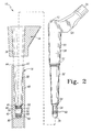
- FIGS. 1-3 there is shown a modular prosthesis 10 for use during performance of a joint replacement procedure such as a hip replacement procedure.
- a joint replacement procedure such as a hip replacement procedure.
- the concepts of the present invention may be utilized in regard to replacement procedures at numerous other joint locations throughout the body.
- the concepts of the present invention may be utilized in the performance of a shoulder or knee replacement procedure.
- the modular femoral prosthesis 10 includes a proximal component such as a proximal neck component 12, a proximal bone fixation or sleeve component 14, a ball or head component 16, and a distal component such as a distal stem component 18.
- the prosthesis 10 is configured to be implanted into a femur 20 (see FIG. 4) of a patient in order to replace certain natural features of the patient's femur 20 as a result of, for example, disease or trauma.
- the modular prosthesis 10 is implanted into a surgically prepared (e.g. reamed and/or broached) medullary canal 22 (see FIG. 4) of the femur 20.
- the modular prosthesis 10 may be press fit into the medullary canal 22, or alternatively, may be secured within the medullary canal 22 by the use of bone cement.
- the prosthesis 10 may be utilized to rotatably secure the patient's femur 20 to the patient's pelvis (not shown).
- the head component 16 is positioned to bear on either the patient's natural acetabulum or a prosthetic socket which has been implanted into the patient's pelvis to replace his or her acetabulum.
- the modular prosthesis 10 and the natural or artificial acetabulum collectively function as a system which replaces the natural "ball and socket" joint of the patient's hip.
- the distal stem component 18 may be provided in a number of different configurations in order to fit the needs of a given patient's anatomy and provide a variety of fixation options (e.g. textures and geometries) and sizes.
- the stem component 18 may be configured in various different lengths in order to conform to the patient's anatomy (e.g. a relatively long stem component 18 for use with a long femur 20, a relatively short stem for use with a short femur 20, etcetera).
- the distal stem component 18 may also be provided in a bow-shaped configuration if required by a given patient's anatomy.
- the distal stem component 18 may also be provided in various diameters and outer textures if required by a given patient's anatomy.
- each of the neck component 12, the sleeve component 14, and the head component 16 may also be provided in various differing configurations in order to provide the flexibility necessary to conform to varying anatomies from patient to patient.
- the head component 16 may be provided in varying diameters or the sleeve component 14 may be provided in varying angles and lengths to fit the needs of a given patient's anatomy.
- both the shape and length of the neck component 26 may also be varied to fit the needs of a given patient's anatomy.
- the proximal neck component 12 includes a body 24 having a support member or trunnion 26 extending outwardly from a proximal end portion thereof. As shown in FIG. 1, the head component 16 is taper fit or otherwise secured to the trunnion 26.
- the body 24 also has a post 28 extending outwardly from a distal end portion thereof.
- both the trunnion 26 and the post 28 are integrally formed with the body 24 of the proximal neck component 12.
- the body 24, the trunnion 26, and the post 28 may be embodied as separate components which are secured to one another by use of fasteners, press fit joints, or taper fit joints.
- the post 28 includes a shoulder mounting portion 30, a tapered portion 32, and an extension portion 34.
- the shoulder mounting portion 30 is configured to be received into an elongated bore 36 defined in the sleeve component 14. As shown in FIG. 2, both the shoulder mounting portion 30 of the post 28 and the elongated bore 36 possess a taper which allows the sleeve component 14 to be taper locked to the post 28 when the post 28 is received into the elongated bore 36.
- the tapered portion 32 of the post 28 is provided to taper lock the proximal neck component 12 to the distal stem component 18.
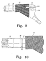
- the tapered portion 32 of the post 28 is received into an elongated bore 38 defined in a sidewall 40 the distal stem component 18.
- both the tapered portion 32 of the post 28 and the elongated bore 38 of the distal stem component 18 are continuously tapered along the entire length thereof.
- the cross sectional diameter of the bore or post either (1) monotonically or otherwise continuously increases (and hence at no point decreases or remains the same) from one end of the bore or post to the other, or (2) monotonically or otherwise continuously decreases (and hence at no point increases or remains the same) from one end of the bore or post to the other.
- the length of the elongated bore 38 is defined by the distance between a post-receiving opening 42 defined in a proximal end surface 44 of the stem component 18 and a proximal end 46 of a threaded aperture 48 defined in a shoulder surface 50 of the sidewall 40.
- the elongated bore 38 is continuously tapered from the post-receiving opening 42 to the proximal end 46 of the threaded aperture 48 since the cross sectional diameter of the elongated bore continuously decreases (i.e. at no point increases or remains the same) from the post-receiving opening 42 to the proximal end 46 of the threaded aperture 48.
- the length of the tapered portion 32 of the post 28 is defined by the distance between a first transitional surface 52 and a second transitional surface 54.
- first transitional surface 52 separates the shoulder mounting portion 30 of the post 28 from the tapered portion 32
- second transitional surface 54 separates the tapered portion 32 from the extension portion 34 of the post 28.
- the tapered portion 32 of the post 28 is continuously tapered from the first transitional surface 52 to the second transitional surface 54 since the cross sectional diameter of the tapered portion 32 of the post 28 continuously decreases (i.e. at no point increases or remains the same) from the first transitional surface 52 of the post 28 to the second transitional surface 54 of the post 28.
- a continuously tapered bore or post such as the elongated bore 38 or the tapered portion 32 of the post 28 of the present invention is distinct from heretofore designed bores and posts which utilize a "stepped" or other type of design in which the cross sectional diameter of the bore or post does not continuously increase or decrease from one end of the bore or post to the other.
- certain heretofore designed orthopedic components utilize a bore which has an elongated cylindrically-shaped (i.e. non-tapered) bore with a tapered "lead-in" portion at one end thereof for facilitating advancement of a cylindrically-shaped post into the bore.
- such a bore design is not continuously tapered since the cross sectional diameter of the bore does not continuously increase or decrease along the entire length thereof. Indeed, in such a design, the cross sectional diameter of the bore decreases throughout the length of the lead-in segment of the bore, but then remains substantially constant throughout the length of the cylindrically-shaped portion of the bore.
- the sidewall 40 of the distal stem component 18 further has a counterbored cavity 56 and second threaded aperture 58 defined therein.
- the elongated bore 38, the threaded aperture 48, the counterbored cavity 56, and the threaded aperture 58 are each arranged coaxially with one another.
- the threaded aperture 48 is interposed between the elongated bore 38 and the counterbored cavity 56.
- the proximal end 46 of the threaded aperture 48 adjoins or otherwise opens into the distal end of the elongated bore 38, whereas a distal end 62 of the threaded aperture adjoins or otherwise opens into the counterbored cavity 56.
- the counterbored cavity 56 is interposed between the threaded apertures 48 and 58 as a result of the coaxial relationship of the features defined in the sidewall 40 of the distal stem member 18.
- a proximal end 64 of the counterbored cavity 56 adjoins or otherwise opens into the threaded aperture 48
- a distal end 66 of the counterbored cavity 56 adjoins or otherwise opens into the threaded aperture 58.
- the configuration of the features defined in the distal stem component 18 cooperate with the features of the proximal neck component 12 to provide for enhanced locking characteristics of the proximal neck component 12 relative to the distal stem component 18.
- the extension portion 34 of the post 28 is substantially cylindrical in shape and has a number of threads 60 extending outwardly therefrom.
- the threads 60 are configured to possess an outer diameter which allows the threads 60 to threadingly engage the threaded aperture 48, while also preventing the threads 60 from contacting the sidewall 40 of the elongated bore 38 or the counterbored cavity 56.
- the outer diameter of the threads 60 is smaller than both (1) the minimum (i.e. smallest) cross sectional inner diameter of the elongated bore 38 (i.e. the cross sectional diameter of the distal end portion of the bore 38), and (2) the cross sectional inner diameter of the counterbored cavity 56.
- the threads 60 of the post 28 are positioned in the counterbored cavity 56, as shown in FIG. 3.
- the extension portion 34 of the post 28 is advanced through the elongated bore 38 of the stem component 18 in a downward or distal direction (as viewed in FIGS. 1-3).
- the proximal neck component 12 and the distal stem component 18 are then twisted or otherwise rotated relative to one another so as to threadingly advance the threads 60 completely through the threaded aperture 48.
- the components 12, 18 are rotated relative one another until each of the threads 60 has completely exited the distal end 62 of the threaded aperture 48.
- the tapered portion 32 of the post 28 is likewise advanced in a downward or distal direction (as viewed in FIGS. 1-3) into the elongated bore 38 of the stem component 18.
- the respective tapers of the tapered portion 32 of the post 28 and the elongated bore 38 are configured such that the tapered portion 32 of the post 28 firmly engages the sidewall 40 of the elongated bore 38 at the point the threads 60 exit the threaded aperture 48. In such a manner, axial and other functional loads exerted on the modular prosthesis 10 do not bear on the threads 60, but rather bear on the proximal neck component 12 and the distal stem member 18 along the tapered interface therebetween.
- the axial length of threads 60 is configured such that the threads 60 do not contact the wall surface associated with the proximal end 64 of the counterbored cavity 56 or the wall surface associated with the distal end 66 of the counterbored cavity 56 when the tapered portion 32 of the post 28 is firmly engaged with the sidewall 40 of the elongated bore 38. This configuration further prevents axial loads (or other types functional loads) from being exerted on the threads 60.
- the aforedescribed configuration provides for enhanced flexibility in regard to the angular positioning of the proximal neck component 12 relative to the distal stem component 18.
- the proximal neck component 12 may be freely rotated through 360° of rotation relative to the distal stem component 18. This is true since the threads 60 are free of the threaded aperture 48 and therefore not restricted thereby.
- the relatively firm contact forces present at the tapered interface between the proximal and distal components 12 and 18 provides resistance to such rotation of the proximal neck component 12. This allows for relatively precise positioning of the neck component since it can be rotated in relatively short "increments" by the surgeon.
- an axial force may be exerted on the two components 12, 18 in order to increase the "taper lock" therebetween so as to prevent further rotation between the two components 12, 18 under normal (and even somewhat excessive) functional loads.
- One way of exerting such an axial force on the two components 12, 18 is by striking the proximal surface of the neck component 12 with a surgical hammer or the like thereby further urging the tapered portion 32 of the post 28 into locking engagement with the sidewall 40 of the elongated bore 38.
- the modular prosthesis 10 may be assembled prior to implantation thereof into the femur 20 of the patient with the final "tweaking" of the angular position of the neck component 12 relative to the stem component 18 being performed subsequent to implantation.
- the modular prosthesis 10 may be implanted into the femur 20 in a fully assembled configuration in which the threads 60 of the post 28 are positioned in the counterbored cavity 56, but prior to exerting the final axial load on the components 12, 18.
- the surgeon would position the neck component 12 in an approximated angular position relative to the stem component 18 prior to implantation, and thereafter position the neck component 12 in its final desired angular position relative to the stem component 18 in vivo (i.e.
- the neck component 12 may be struck with the surgical hammer, in vivo, in the manner described above in order to strengthen the taper lock of the components 12, 18 relative to one another.
- the aforedescribed configuration also prevents undesirable separation of the proximal neck component 12 from the distal stem component 18.
- the post 28 of the neck component 12 is prevented from advancing out of the elongated bore 38 since the threads 60 cannot be advanced back through the threaded aperture 48 without rotating the two components 12,18 relative to one another through a number of complete rotations.
- the proximal neck component 12 is prevented from moving in an upward or proximal direction (as viewed in FIGS.
- the threads 60 function as "blocking members" which block or otherwise prevent separation of the two components 12,18 from one another.
- the aforedescribed configuration of the post 28 and the stem component 18 may again be utilized.
- the taper lock between the proximal and distal components 12, 18 must first be "broken". This may be accomplished by exerting a force, such as a blow from a surgical hammer, on the proximal neck component 18. Thereafter, the proximal neck component 18 is rotated in the opposite direction from which it was rotated during implantation of the prosthesis 10 so as to advance the threads 60 back into the threaded aperture 48.
- the surgeon may pull or otherwise exert a force on the proximal neck component 12 in an upward or proximal direction (as viewed in FIGS. 1-4) in order to urge the modular prosthesis 10 out of the medullary canal 22 of the patient's femur 20.
- the threaded aperture 58 is provided to facilitate extraction of the modular prosthesis 10 in the event that, for example, the threads of the threaded aperture 48 become damaged (e.g. stripped).
- another manner for removing the modular prosthesis 10 may be utilized. In such a case, all of the components associated with the modular prosthesis 10 except the implanted distal stem component 18 are first removed thereby leaving only the implanted distal stem component 18 in the femur 20 (see FIG. 4).
- replacement components may be secured to the implanted distal stem component 18 in the manner previously discussed.
- a replacement proximal neck component 12, a replacement sleeve component 14, and a replacement head component 16 may be secured to the implanted distal stem component 18 in the manner previously discussed.
- a removal tool 70 may be utilized to extract the distal stem component 18.
- the removal tool 70 has an elongated shaft 72 having a number of threads 74 extending outwardly from one end thereof.
- the other end of the elongated shaft 72 has a T-shaped handle 76 secured thereto.
- the threads 74 possess an outer diameter which allows for threading engagement with the threaded aperture 58 of the distal stem member 18. In such a manner, the threads 74 of the removal tool 70 may be threaded into the threaded aperture 58 so as to secure the tool 70 to the distal stem component 18.
- surgeon may pull or otherwise exert a force on the handle 76 in an upward or proximal direction (as viewed in FIG. 4) in order to urge the distal stem component 18 out of the medullary canal 22 of the patient's femur 20.
- the post 28 and/or the threaded aperture 58 may be configured to prevent advancement of the threads 60 of the post 28 into the threaded aperture 58.
- the length in which the extension portion 34 of the post 28 extends beyond the lower (i.e. distal) surface of the lowermost thread 60 causes a distal tip 78 of the post 28 to "bottom out” or otherwise contact a bottom sidewall surface 80 of the aperture 58 before the lowermost thread 60 can come into contact with the threaded aperture 58.
- the threaded aperture 58 may also be configured to possess an internal thread diameter and/or thread class which is different than the external thread diameter and/or thread class of the threads 60 of the post 28 thereby preventing the threads 60 from threadingly engaging the threaded aperture 58.
- the threaded aperture 58 is configured to possess an internal thread diameter which is smaller than the external thread diameter of the threads 60 of the post 28 thereby preventing the threads 60 from threadingly engaging the threaded aperture 58.
- the cross sectional outer diameter of the cylindrically-shaped, non-threaded segments of the extension portion 34 is configured to be slightly smaller than the internal diameter of the threaded aperture 58.
- the non-threaded distal tip 78 may be received into the threaded aperture 58 without contacting the threads of the threaded aperture 58 thereby preventing the distal tip 78 from damaging the threads of the aperture 58.
- the distal tip 78 of the post 28 protects the threads of the threaded aperture 58 by preventing debris or the like from entering the aperture 58.
- the femoral modular prosthesis 10 of the present invention is implanted into the medullary canal 22 of the femur 20 during performance of a hip replacement procedure.
- the medullary canal 22 of the femur 20 is first reamed, broached, or otherwise surgically prepared by the surgeon. Thereafter, the modular prosthesis 10 may then be implanted into the femur 20. It should be appreciated that if bone cement is utilized to secure the modular prosthesis within the femur, the medullary canal 22 is filled with such cement prior to implantation of the modular prosthesis 10.
- the modular prosthesis 10 is generally pre-assembled.
- a head component 16 of a desirable size is first selected and thereafter taper or press fit onto the trunnion 26 of the proximal neck component 12 (although in some cases it may be desirable to secure the head component 16 subsequent to implantation of the prosthesis 10 in order to allow for the selection of a head component 16 having a desirable length based on the surgeon's final leg length adjustment).
- the sleeve component 14 is then secured to the post 28 of the neck component 12.
- the post 28 is advanced through the elongated bore 36 of the sleeve component 14 such that the shoulder mounting portion 30 of the post 28 is received therethrough.
- the taper of both the shoulder mounting portion 30 of the post 28 and the elongated bore 36 allows the sleeve component 14 to be taper locked to the post 28 when the post 28 is received into the elongated bore 36.
- a distal stem component 18 having a desired configuration is selected and thereafter secured to the proximal neck component 12.
- the extension portion 34 of the post 28 is first advanced in a downward or distal direction (as viewed in FIGS. 1-3) through the elongated bore 38 of the stem component 18.
- the proximal neck component 12 and the distal stem component 18 are then twisted or otherwise rotated relative to one another by the surgeon so as to threadingly advance the threads 60 into the threaded aperture 48.
- the proximal and distal components 12 and 18 continue to be rotated relative to one another until the threads 60 have completely exited the distal end 62 of the threaded aperture 48.
- the tapered portion 32 of the post 28 is likewise advanced in a downward or distal direction (as viewed in FIGS. 1-3) into the elongated bore 38 of the stem component 18.
- the respective tapers of the tapered portion 32 of the post 28 and the elongated bore 38 are configured such that the tapered portion 32 of the post 28 firmly engages the sidewall 40 of the elongated bore 38 as the threads 60 exit the threaded aperture 48 (and before the threads 60 contact the threaded aperture 58).
- the angular position of the proximal neck component 12 relative to the distal stem component 18 may be adjusted by the surgeon in order to position the neck component 12 and hence the head component 16 in a desirable location relative to the patient's acetabulum (or artificial acetabular surface).
- the proximal neck component 12 may be freely rotated through 360° of rotation relative to the distal stem component 18.
- firm contact at the tapered interface between the proximal and distal components 12,18 provides a desirable level of resistance to such rotation of the proximal neck component 12 in order to provide for more precise locating of the component 12.
- the surgeon may desire to position the neck component 12 in an approximated angular position relative to the stem component 18 prior to implantation, and wait to position the neck component 12 in its final desired angular position relative to the stem component 18 in vivo (i.e. subsequent to implantation into the patient's femur 20). If this is the case (as it is for purposes of this exemplary discussion), the surgeon would at this point implant the modular prosthesis 10 into the medullary canal 22 of the femur 20. In particular, the surgeon would advance the distal tip 78 of the distal stem component 18 into the prepared medullary canal 22 of the femur 20 to a desired depth within the canal 22.
- the sleeve component 14 contacts the surfaces of the femur 20 near the opening at the proximal end of the femur 20 in order to position the proximal end of the prosthesis 10 in a desired orientation.
- the neck component 12 extends out of the medullary canal 22 in a direction which allows the head component 14 to be positioned so as to bear on the patient's acetabulum (or an artificial replacement thereof).
- the various prosthetic components discussed above may be assembled and implanted into the femur 20 as described above, it is contemplated that these various components may be assembled and implanted in any manner a surgeon may deem appropriate for a particular surgical situation.
- the sleeve component 14 may be initially implanted in the femur 20, and thereafter, a subassembly made up of an assembled proximal neck component 12, distal stem component 18, and head component 16, may be advanced through the elongate bore 36 of the implanted sleeve component 14 to carry out the implantation procedure.
- the elongate bore 36 of the sleeve component 14 would need to be modified to possess a size sufficient to allow the distal stem component 18 to be advanced through the elongate bore 36.
- the surgeon in vivo, positions the proximal neck component 12 in a desired, final angular position relative to the distal stem component 18. Thereafter, an axial force may be exerted on the two components 12, 18 in order to increase the "taper lock" between the two components 12, 18 thereby preventing further rotation between the two components 12, 18 under normal (and even somewhat excessive) functional loads.
- the surgeon strikes the proximal surface of the neck component 12 with a surgical hammer or the like thereby further urging the tapered portion 32 of the post 28 into locking engagement with the sidewall 40 of the elongated bore 38.
- the taper lock between the proximal and distal components 12, 18 is first "broken” by exerting a force, such as a blow from a surgical hammer, on the proximal neck component 18. Thereafter, the proximal neck component 18 is rotated in the opposite direction in which is was rotated during implantation of the prosthesis 10 so as to advance the threads 60 back into the threaded aperture 48.
- the surgeon may pull or otherwise exert a force on the proximal neck component 12 in an upward or proximal direction (as viewed in FIGS. 1-4) in order to urge the modular prosthesis 10 out of the medullary canal 22 of the patient's femur 20.
- a replacement proximal neck component 12 may be secured to the implanted distal stem component 18 in the manner previously discussed.
- the removal tool 70 may be utilized to extract the modular prosthesis 10 from the femur 20.
- the threads of the threaded aperture 48 are damaged and therefore unable to engage the threads 60 of the post 28, all of the components associated with the modular prosthesis 10 except the implanted distal stem component 18 are first removed thereby leaving only the implanted stem component 18 in the medullary canal 22 of the femur 20, as shown in FIG. 4. Thereafter, the shaft 72 of the removal tool 70 is threaded into the threaded aperture 58 so as to secure the tool 70 to the distal stem component 18.
- surgeon may pull or otherwise exert a force on the handle 76 in an upward or proximal direction (as viewed in FIG. 4) in order to urge the distal stem component 18 out of the medullary canal 22 of the patient's femur 20.
- the modular prosthesis 10 of the present invention provides numerous advantages over heretofore designed prostheses.
- the proximal component i.e. the neck component 12
- the distal component i.e. the distal stem component 18
- an internally tapered component i.e. the elongated bore 38
- the modular prosthesis 10 of the present invention possesses "self locking" characteristics that are not present in prior prosthesis designs.
- functional loads exerted on the modular prosthesis 10 during use thereof tend to urged the proximal neck component 12 in a downward or distal direction (as viewed in FIGS.
- the configuration of the modular prosthesis 10 also provides enhanced load bearing characteristics relative to heretofore designed prostheses. For example, axial and other functional loads exerted on the modular prosthesis 10 bear on the proximal neck component 12 and the distal stem member 18 along the tapered interface therebetween as opposed to the threads 60 of the post 28. This distributes such loads over a relatively large surface area relative to heretofore designed prostheses in which such axial loads bear directly on the threads of the fastener (e.g. bolt or screw) which is utilized to secure the components of the prosthesis to one another.
- the fastener e.g. bolt or screw
- the configuration of the modular prosthesis 10 of the present invention eliminates the need for use of a separate fastener such as an elongated bolt or screw to secure the neck component to the stem component.
- a separate fastener such as an elongated bolt or screw to secure the neck component to the stem component.
- difficult manufacturing techniques such as gun drilling are also eliminated thereby lowering costs associated with manufacture of the modular prosthesis 10.
- the aforedescribed configuration of the modular prosthesis of the present invention provides for enhanced flexibility in regard to the angular positioning of the proximal neck component 12 and hence the head component 16 relative to the patient's acetabulum (or an artificial acetabular surface).
- the surgeon may position the head component 16 in a more precise location relative to the location in which he or she can position a head component of a heretofore designed prosthesis.
- the aforedescribed configuration of the modular prosthesis 10 of the present invention also provides enhanced security from separation relative to heretofore designed prostheses. This is true since the post 28 of the neck component 12 is prevented from advancing out of the elongated bore 38 by the fact that the threads 60 cannot be advanced back through the threaded aperture 48 without rotating the two components 12, 18 relative to one another through a number of complete rotations.
- the use of the threaded aperture 58 provides a manner by which extraction of the modular prosthesis 10 may be accomplished in the event that, for example, the threads of the threaded aperture 48 become damaged (e.g. stripped).
- This provides a backup solution that is not present in other prosthesis designs.
- backup features are generally not provided for the threads of the threaded bore which receives the locking fastener of heretofore designed modular prostheses thereby potentially causing significant problems in the event that the surgeon is not able to extract the stem component by use of such threads.
- the concepts of the present invention may be utilized in the construction of other types prosthetic components in addition to the femoral components described herein.
- the use of the features associated with the post 28 and the corresponding features defined in the stem component 18 may be utilized to secure numerous different types of prosthetic components to one another.
- the modular prosthesis 10 is described herein as being configured such that the proximal component (i.e. the neck component 12) includes the externally tapered structure (i.e. the post 28) and the distal component (i.e. the distal stem component 18) includes the internally tapered structure (i.e. the elongated bore 38), and has significant advantages thereby in the present invention, certain of such advantages may be achieved by other configurations.
- the proximal component i.e. the neck component 12
- the proximal component may be configured to include an internally tapered structure similar to the elongated bore 38 for receiving an externally tapered structure similar to the post 28 associated with the distal component.
- FIG. 5 there is shown another embodiment of a modular prosthesis (hereinafter referred to with reference numeral 100) which incorporates the features of the present invention therein.
- the modular prosthesis 100 is somewhat similar to the modular prosthesis 10. Accordingly, the modular prosthesis 100 includes a number of features which are identical to certain of the features previously discussed in regard to the modular prosthesis 10.
- the same reference numerals are utilized in FIG. 5 to designate identical features which were previously discussed in regard to FIGS. 1-4 and additional discussion thereof is not warranted.
- the modular prosthesis 100 is essentially the same as the modular prosthesis 10 except that the post 28 is secured to a proximal end of the stem component 18, whereas the elongated bore 38 and the counterbored cavity 56 are defined in the neck component 12.
- the threads 60 of the post 28 are positionable in the counterbored cavity 56 when the tapered portion 32 of the post 28 firmly engages the sidewall 40 of the elongated bore 38 as the threads 60 exit the threaded aperture 48 (and before the threads 60 contact the threaded aperture 58).
- FIGS. 6-12 there is shown yet another embodiment of a modular prosthesis (hereinafter referred to with reference numeral 200) which incorporates the features of the present invention therein.
- the modular prosthesis 200 is somewhat similar to the modular prostheses 10, 100. Accordingly, the modular prosthesis 200 includes a number of features which are identical to certain of the features previously discussed in regard to the modular prosthesis 10, 100.
- the same reference numerals are utilized in FIGS. 6-12 to designate identical features which were previously discussed in regard to FIGS. 1-5 and additional discussion thereof is not warranted.
- the modular prosthesis 200 is essentially the same as the modular prosthesis 100 except that a counterbored cavity 56 is not defined in the neck component 12. Rather, a recess 210 is defined in the neck component as shown in FIGS. 12A and 12B. Moreover, retention of the post 28 of the stem component 18 within the elongated bore 38 of the neck component may be assisted by use of a retainer 202. Note that the retainer 202 is internally threaded so as to engage the external threads defined on the post 28.
- FIGS. 13-14 there is shown still another embodiment of a modular prosthesis (hereinafter referred to with reference numeral 300) which incorporates the features of the present invention therein.
- the modular prosthesis 300 is somewhat similar to the modular prosthesis 100. Accordingly, the modular prosthesis 300 includes a number of features which are identical to certain of the features previously discussed in regard to the modular prosthesis 100.
- the same reference numerals are utilized in FIGS. 13-14 to designate identical features which were previously discussed in regard to FIG. 5, and thus additional discussion thereof is not warranted.
- the modular prosthesis 300 is essentially the same as the modular prosthesis 100 except that a counterbored cavity 56 is not defined in the neck component 12. Rather, the neck component 12 has a passageway 230 defined therein as shown in FIGS. 13-14. Moreover, retention of the post 28 of the stem component 18 within the elongated bore 38 of the neck component may be assisted by use of a fastener 232. Note that the fastener 232 has an externally threaded portion 250 which is configured to engage an internally threaded portion 252 defined in the post 28 as shown in FIGS. 13 and 14.
Abstract
Description
- This application is related to the co-pending European patent application No. filed concurrently herewith, which claims priority from USSN 60/246854 (Attorney's ref: P028708EP), the disclosure of which is incorporated herein by reference.
- The present invention relates generally to a prosthesis, and more particularly to a self-locking modular prosthesis having a stem component with a tapered bore for receiving a tapered post of a neck component and associated method.
- During the lifetime of a patient, it may be necessary to perform a joint replacement procedure on the patient as a result of, for example, disease or trauma. The joint replacement procedure may involve the use of a prosthesis which is implanted into one of the patient's bones. In the case of a hip replacement procedure, a femoral prosthesis is implanted into the patient's thigh bone or femur. The femoral prosthesis is typically constructed as a one-piece structure having an upper portion which includes a spherically-shaped head which bears against the patient's pelvis or acetabulum, along with an elongated intramedullary stem which is utilized to secure the femoral component to the patient's femur. In order to secure the prosthesis to the patient's femur, the medullary canal of the patient's femur is first surgically prepared (e.g. reamed and/or broached) such that the intramedullary stem of the femoral prosthesis may be subsequently implanted therein. The femoral prosthesis may be press fit into the medullary canal or, in the alternative, bone cement may be utilized to secure the femoral prosthesis within the medullary canal.
- During performance of a joint replacement procedure, it is generally necessary to provide the surgeon with a certain degree of flexibility in the selection of a prosthesis. In particular, the anatomy of the bone into which the prosthesis is to be implanted may vary somewhat from patient to patient. For example, in the case of a femoral prosthesis, the patient's femur may be relatively long or relatively short thereby requiring use of a femoral prosthesis which includes a stem that is relatively long or short, respectively. Moreover, in certain cases, such as when use of a relatively long stem length is required, the stem must also be bowed in order to conform to the anatomy of the patient's femur.
- Such a need for prostheses of varying shapes and sizes this creates a number of problems in regard to use of a one-piece prosthesis. For example, a hospital or surgery center must maintain a relatively large inventory of prostheses in order to have the requisite mix of prostheses needed for certain situations such as trauma situations and revision surgery. Moreover, since the bow of the stem must conform to the bow of the intramedullary canal of the patient's femur, rotational positioning of the upper portion (i.e. proximal end) of the prosthesis is limited thereby rendering precise locating of the upper portion and hence the head of the prosthesis very difficult. In addition, since corresponding bones of the left and right side of a patient's anatomy (e.g. left and right femur) may bow in opposite directions, it is necessary to produce "left" and "right" variations of the prosthesis in order to provide anteversion of the bowed stem thereby further increasing the inventory of prostheses which must be maintained.
- As a result of these and other drawbacks, a number of modular prostheses have been designed. As its name implies, a modular prosthesis is constructed in modular form so that the individual elements or features of the prosthesis can be selected to fit the needs of a given patient's anatomy. For example, modular prosthesis have been designed which include a proximal neck component which can be assembled to any one of numerous distal stem components in order to create an assembly which fits the needs of a given patient's anatomy. Such a design allows the distal stem component to be selected and thereafter implanted in the patient's bone in a position which conforms to the patient's anatomy while also allowing for a limited degree of independent positioning of the proximal neck component relative to the patient's pelvis.
- One issue that arises as a result of use of a modular prosthesis is the locking of the components relative to one another. In particular, firm locking of the proximal neck component to the distal stem component is critical to prevent separation of the two components subsequent to implantation thereof into the patient. As such, a number of locking mechanisms have heretofore been designed to lock the components of a modular prosthesis to one another. For example, a number of modular prostheses have heretofore been designed to include a distal stem component which has an upwardly extending post which is received into a bore defined in the distal neck component. A relatively long fastener, such as a screw or bolt, is utilized to secure the post within the bore.
- However, such a design has a number of drawbacks associated therewith. Firstly, functional loading during use of the prosthesis may not provide a positive lock and may actually tend to urge the upwardly extending post of the distal stem component out of the bore defined in the proximal neck component. In such a case, the fastener (e.g. the screw or bolt) alone must absorb such loads. This creates a number of problems since many of such functional loads tend to be axial in nature. In particular, by the nature of its design, axial loads exerted on a fastener such as a screw or bolt bear on the threads of the fastener thereby undesirably exerting a relatively large load to a relatively small surface area. Over time, such loads may degrade or even breach the mechanical integrity of the threads thereby potentially allowing the components to separate from one another.
- Secondly, manufacture of such modular prosthesis is relatively difficult and, as a result, expensive. In particular, in order to utilize a long screw or bolt to secure the two components to one another, a relatively long bore must be drilled or otherwise machined through the entire length of the proximal neck component and at least a portion of the length of the distal stem component. Such drilling, often referred to as "gun drilling", is relatively difficult to do since, amongst other things, it requires adherence to extremely strict tolerances thereby increasing costs associated with manufacture of the modular prosthesis.
- What is needed therefore is a modular prosthesis which overcomes one or more of the above-mentioned drawbacks. What is particularly needed is a modular prosthesis which has enhanced locking characteristics relative to heretofore designed modular prostheses. What is further particularly needed is a modular prosthesis that is "self-locked" by the functional loads generated during use of the prosthesis.
- In accordance with one embodiment of the present invention, there is provided a modular prosthesis. The prosthesis includes a stem member having an elongated bore and a threaded aperture defined therein. The stem member has a proximal end surface which has a post-receiving opening defined therein. The elongated bore extends between the post-receiving opening and the threaded aperture. The elongated bore is continuously tapered from the post-receiving opening to the threaded aperture. The prosthesis also includes a neck member having a neck body, a head-receiving support member secured to the neck body so as to extend outwardly therefrom, and a tapered post secured to the neck body so as to extend outwardly therefrom. The tapered post is adapted to be received into the elongated bore of the stem member.
- In accordance with another embodiment of the present invention, there is provided a modular femoral prosthesis. The femoral prosthesis includes a stem member adapted to be implanted into a medullary canal of a femur. The stem member has a continuously tapered elongated bore and a threaded aperture defined therein. A first end of the elongated bore defines a post-receiving opening. The post-receiving opening is defined in a proximal end surface of the stem member. The elongated bore extends between the post-receiving opening and a threaded aperture. The femoral prosthesis also includes a neck member having a neck body, a head-receiving support member secured to the neck body so as to extend outwardly therefrom, and a tapered post secured to the neck body so as to extend outwardly therefrom. The tapered post is adapted to be received into the elongated bore of the stem member.
- In accordance with a further embodiment of the present invention, there is provided a method of performing a joint replacement procedure by use of a modular prosthesis. The modular prosthesis includes a neck member having a neck body, a head-receiving support member secured to the neck body so as to extend outwardly therefrom, and a tapered post secured to the neck body so as to extend outwardly therefrom. The modular prosthesis also includes a stem member which has an elongated bore and a threaded aperture defined therein. The method includes the step of advancing the tapered post into a post-receiving opening defined in a proximal end surface of the stem member. The post-receiving opening defines a proximal end of the elongated bore. The threaded aperture defines a distal end of the elongated bore. The elongated bore is continuously tapered from the post-receiving opening to the threaded aperture. The method also includes the step of implanting the stem member into a bone.
- Pursuant to yet another embodiment of the present invention, there is provided a modular prosthesis which includes a neck member having an elongated bore and a threaded aperture defined therein, wherein (i) the neck member has a distal end surface which has a post-receiving opening defined therein, (ii) the elongated bore extends between the post-receiving opening and the threaded aperture, and (iii) the elongated bore is continuously tapered from the post-receiving opening to the threaded aperture. The modular prosthesis further includes a stem member having a tapered post which is configured to be received in the elongated bore of the stem member.
- According to yet another embodiment of the present invention, there is provided a modular prosthesis which includes a first prosthetic component having an elongated bore and a threaded aperture defined therein, wherein (i) the first prosthetic component has an end surface which has a post-receiving opening defined therein, (ii) the elongated bore extends between the post-receiving opening and the threaded aperture, and (iii) the elongated bore is continuously tapered from the post-receiving opening to the threaded aperture. The modular prosthesis further includes a second prosthetic member having a tapered post which is configured to be received in the elongated bore of the first prosthetic component.
- It is therefore an object of the present invention to provide a new and useful modular prosthesis.
- It is moreover an object of the present invention to provide an improved modular prosthesis.
- It is a further object of the present invention to provide a new and useful method of performing a joint replacement procedure by use of a modular prosthesis.
- It is also an object of the present invention to provide an improved method of performing a joint replacement procedure by use of a modular prosthesis.
- It is yet another object of the present invention to provide a modular prosthesis which has enhanced locking characteristics relative to heretofore designed modular prostheses.
- It is moreover an object of the present invention to provide a modular prosthesis that is "self-locked" by the functional loads generated during use of the prosthesis.
- It is also an object of the present invention to provide a modular prosthesis that provides a high degree of flexibility in regard to the positioning of the head component thereof relative to the patient's acetabulum.
- The above and other objects, features, and advantages of the present invention will become apparent from the following description and the attached drawings.
-
- FIG. 1 is an exploded perspective view of a modular prosthesis which incorporates the features of the present invention therein;
- FIG. 2 is an exploded, enlarged fragmentary cross sectional view which shows the proximal neck component, the sleeve component, and the distal stem component of the modular prosthesis of FIG. 1, note that the proximal neck component is not shown in cross section for clarity of description;
- FIG. 3 is a cross sectional view similar to FIG. 2, but showing the components of the modular prosthesis assembled to one another;
- FIG. 4 is a cross sectional view which shows the distal stem portion of the modular prosthesis of FIG. 1 just before being extracted from a patient's femur by use of a removal tool (Note that the removal tool is shown being advanced to a position in which its distal portion threadingly engages a complementary threaded part of the distal stem portion);
- FIG. 5 is a view similar to FIG. 3, but showing still another modular prosthesis which incorporates the features of the present invention therein;
- FIG. 6 is view similar to FIG. 1, but showing yet another modular prosthesis which incorporates the features of the present invention therein;
- FIG. 7 is view similar to FIG. 6, but showing the head component removed for clarity of description;
- FIG. 8 is a side elevational view similar to FIG. 7, but showing the components of the modular prosthesis assembled to one another;
- FIG. 9 is an enlarged view of a portion of the modular prosthesis of FIG. 8;
- FIG. 10 is an enlarged view of a portion of the modular prosthesis of FIG. 9;
- FIG. 11A is a view somewhat similar to FIG. 8, but showing the sleeve component removed for clarity of viewing;
- FIG. 11B is an enlarged view of a portion of the modular prosthesis of FIG. 11A that is encircled and labeled as FIG. 11B;
- FIG. 12A is a partial cross sectional of the neck component and stem component of the modular prosthesis of FIG. 6;
- FIG. 12B is cross sectional view of the neck component of the modular prosthesis of FIG. 6;
- FIG. 12C is a top elevational view of the modular prosthesis of FIG. 8, with the retainer removed for clarity of viewing;
- FIG. 12D is partial cross sectional view of the stem component of the modular prosthesis of FIG. 6;
- FIG. 13 is a view similar to FIG. 3, but showing yet still another modular prosthesis which incorporates the features of the present invention therein; and
- FIG. 14 is an enlarged view of a portion of the modular prosthesis of FIG. 13.
-
- While the invention is susceptible to various modifications and alternative forms, a specific embodiment thereof has been shown by way of example in the drawings and will herein be described in detail. It should be understood, however, that there is no intent to limit the invention to the particular form disclosed, but on the contrary, the intention is to cover all modifications, equivalents, and alternatives falling within the spirit and scope of the invention as defined by the appended claims.
- Referring now to FIGS. 1-3, there is shown a
modular prosthesis 10 for use during performance of a joint replacement procedure such as a hip replacement procedure. It should be appreciated that although the present invention is herein exemplarily described in regard to performance of a hip replacement procedure, the concepts of the present invention may be utilized in regard to replacement procedures at numerous other joint locations throughout the body. For example, the concepts of the present invention may be utilized in the performance of a shoulder or knee replacement procedure. - The modular
femoral prosthesis 10 includes a proximal component such as aproximal neck component 12, a proximal bone fixation orsleeve component 14, a ball orhead component 16, and a distal component such as adistal stem component 18. Theprosthesis 10 is configured to be implanted into a femur 20 (see FIG. 4) of a patient in order to replace certain natural features of the patient'sfemur 20 as a result of, for example, disease or trauma. In particular, once assembled in the manner described below, themodular prosthesis 10 is implanted into a surgically prepared (e.g. reamed and/or broached) medullary canal 22 (see FIG. 4) of thefemur 20. Themodular prosthesis 10 may be press fit into themedullary canal 22, or alternatively, may be secured within themedullary canal 22 by the use of bone cement. - In such a manner, the
prosthesis 10 may be utilized to rotatably secure the patient'sfemur 20 to the patient's pelvis (not shown). In particular, thehead component 16 is positioned to bear on either the patient's natural acetabulum or a prosthetic socket which has been implanted into the patient's pelvis to replace his or her acetabulum. In such a manner, themodular prosthesis 10 and the natural or artificial acetabulum collectively function as a system which replaces the natural "ball and socket" joint of the patient's hip. - As shown in FIG. 1, the
distal stem component 18 may be provided in a number of different configurations in order to fit the needs of a given patient's anatomy and provide a variety of fixation options (e.g. textures and geometries) and sizes. In particular, thestem component 18 may be configured in various different lengths in order to conform to the patient's anatomy (e.g. a relativelylong stem component 18 for use with along femur 20, a relatively short stem for use with ashort femur 20, etcetera). Moreover, thedistal stem component 18 may also be provided in a bow-shaped configuration if required by a given patient's anatomy. Yet further, thedistal stem component 18 may also be provided in various diameters and outer textures if required by a given patient's anatomy. - Moreover, it should also be appreciated that, although not shown in FIGS. 1-4, each of the
neck component 12, thesleeve component 14, and thehead component 16 may also be provided in various differing configurations in order to provide the flexibility necessary to conform to varying anatomies from patient to patient. For example, thehead component 16 may be provided in varying diameters or thesleeve component 14 may be provided in varying angles and lengths to fit the needs of a given patient's anatomy. Moreover, both the shape and length of theneck component 26 may also be varied to fit the needs of a given patient's anatomy. - As shown in FIGS. 1-3, the
proximal neck component 12 includes abody 24 having a support member ortrunnion 26 extending outwardly from a proximal end portion thereof. As shown in FIG. 1, thehead component 16 is taper fit or otherwise secured to thetrunnion 26. Thebody 24 also has apost 28 extending outwardly from a distal end portion thereof. In the exemplary embodiment shown in FIGS. 1-3, both thetrunnion 26 and thepost 28 are integrally formed with thebody 24 of theproximal neck component 12. However, it should be appreciated that thebody 24, thetrunnion 26, and thepost 28 may be embodied as separate components which are secured to one another by use of fasteners, press fit joints, or taper fit joints. - The
post 28 includes ashoulder mounting portion 30, a taperedportion 32, and anextension portion 34. Theshoulder mounting portion 30 is configured to be received into anelongated bore 36 defined in thesleeve component 14. As shown in FIG. 2, both theshoulder mounting portion 30 of thepost 28 and the elongated bore 36 possess a taper which allows thesleeve component 14 to be taper locked to thepost 28 when thepost 28 is received into theelongated bore 36. - The tapered
portion 32 of thepost 28 is provided to taper lock theproximal neck component 12 to thedistal stem component 18. In particular, the taperedportion 32 of thepost 28 is received into anelongated bore 38 defined in asidewall 40 thedistal stem component 18. As shown in FIG. 2, both the taperedportion 32 of thepost 28 and the elongated bore 38 of thedistal stem component 18 are continuously tapered along the entire length thereof. What is meant herein by the term "continuously tapered" as utilized in regard to a tapered bore or tapered post is that the cross sectional diameter of the bore or post either (1) monotonically or otherwise continuously increases (and hence at no point decreases or remains the same) from one end of the bore or post to the other, or (2) monotonically or otherwise continuously decreases (and hence at no point increases or remains the same) from one end of the bore or post to the other. - For example, as shown in FIG. 2, the length of the elongated bore 38 is defined by the distance between a
post-receiving opening 42 defined in aproximal end surface 44 of thestem component 18 and aproximal end 46 of a threadedaperture 48 defined in ashoulder surface 50 of thesidewall 40. As such, the elongated bore 38 is continuously tapered from thepost-receiving opening 42 to theproximal end 46 of the threadedaperture 48 since the cross sectional diameter of the elongated bore continuously decreases (i.e. at no point increases or remains the same) from thepost-receiving opening 42 to theproximal end 46 of the threadedaperture 48. - Similarly, the length of the tapered
portion 32 of thepost 28 is defined by the distance between a firsttransitional surface 52 and a secondtransitional surface 54. As shown in FIGS. 2 and 3, the firsttransitional surface 52 separates theshoulder mounting portion 30 of thepost 28 from the taperedportion 32, whereas the secondtransitional surface 54 separates the taperedportion 32 from theextension portion 34 of thepost 28. As such, the taperedportion 32 of thepost 28 is continuously tapered from the firsttransitional surface 52 to the secondtransitional surface 54 since the cross sectional diameter of the taperedportion 32 of thepost 28 continuously decreases (i.e. at no point increases or remains the same) from the firsttransitional surface 52 of thepost 28 to the secondtransitional surface 54 of thepost 28. - Hence, a continuously tapered bore or post such as the elongated bore 38 or the tapered
portion 32 of thepost 28 of the present invention is distinct from heretofore designed bores and posts which utilize a "stepped" or other type of design in which the cross sectional diameter of the bore or post does not continuously increase or decrease from one end of the bore or post to the other. For example, certain heretofore designed orthopedic components utilize a bore which has an elongated cylindrically-shaped (i.e. non-tapered) bore with a tapered "lead-in" portion at one end thereof for facilitating advancement of a cylindrically-shaped post into the bore. However, such a bore design is not continuously tapered since the cross sectional diameter of the bore does not continuously increase or decrease along the entire length thereof. Indeed, in such a design, the cross sectional diameter of the bore decreases throughout the length of the lead-in segment of the bore, but then remains substantially constant throughout the length of the cylindrically-shaped portion of the bore. - The
sidewall 40 of thedistal stem component 18 further has a counterboredcavity 56 and second threadedaperture 58 defined therein. As shown in FIG. 2, the elongated bore 38, the threadedaperture 48, the counterboredcavity 56, and the threadedaperture 58 are each arranged coaxially with one another. As such, the threadedaperture 48 is interposed between theelongated bore 38 and the counterboredcavity 56. Indeed, theproximal end 46 of the threadedaperture 48 adjoins or otherwise opens into the distal end of the elongated bore 38, whereas adistal end 62 of the threaded aperture adjoins or otherwise opens into the counterboredcavity 56. - In a similar manner, the counterbored
cavity 56 is interposed between the threadedapertures sidewall 40 of thedistal stem member 18. In particular, as shown in FIG. 2, aproximal end 64 of the counterboredcavity 56 adjoins or otherwise opens into the threadedaperture 48, whereas adistal end 66 of the counterboredcavity 56 adjoins or otherwise opens into the threadedaperture 58. As shall be discussed below in greater detail, the configuration of the features defined in thedistal stem component 18 cooperate with the features of theproximal neck component 12 to provide for enhanced locking characteristics of theproximal neck component 12 relative to thedistal stem component 18. - As shown in FIGS. 1-3, the
extension portion 34 of thepost 28 is substantially cylindrical in shape and has a number ofthreads 60 extending outwardly therefrom. Thethreads 60 are configured to possess an outer diameter which allows thethreads 60 to threadingly engage the threadedaperture 48, while also preventing thethreads 60 from contacting thesidewall 40 of the elongated bore 38 or the counterboredcavity 56. Indeed, the outer diameter of thethreads 60 is smaller than both (1) the minimum (i.e. smallest) cross sectional inner diameter of the elongated bore 38 (i.e. the cross sectional diameter of the distal end portion of the bore 38), and (2) the cross sectional inner diameter of the counterboredcavity 56. - Subsequent to assembly of the
modular prosthesis 10, thethreads 60 of thepost 28 are positioned in the counterboredcavity 56, as shown in FIG. 3. In particular, theextension portion 34 of thepost 28 is advanced through the elongated bore 38 of thestem component 18 in a downward or distal direction (as viewed in FIGS. 1-3). Theproximal neck component 12 and thedistal stem component 18 are then twisted or otherwise rotated relative to one another so as to threadingly advance thethreads 60 completely through the threadedaperture 48. Specifically, thecomponents threads 60 has completely exited thedistal end 62 of the threadedaperture 48. - As the
threads 60 are advanced through the threadedaperture 48 in the manner described above, the taperedportion 32 of thepost 28 is likewise advanced in a downward or distal direction (as viewed in FIGS. 1-3) into the elongated bore 38 of thestem component 18. The respective tapers of the taperedportion 32 of thepost 28 and the elongated bore 38 are configured such that the taperedportion 32 of thepost 28 firmly engages thesidewall 40 of the elongated bore 38 at the point thethreads 60 exit the threadedaperture 48. In such a manner, axial and other functional loads exerted on themodular prosthesis 10 do not bear on thethreads 60, but rather bear on theproximal neck component 12 and thedistal stem member 18 along the tapered interface therebetween. In fact, since thethreads 60 have completely exited the threaded aperture 48 (and hence positioned in the counterbored cavity 56), no axial loads (or other types functional loads whatsoever) are exerted on thethreads 60. This is true since, as described above, the outer diameter of thethreads 60 is smaller than the inner diameter of the counterboredcavity 56 thereby spacing the outer surfaces of thethreads 60 apart fromsidewall 40 of the counterboredcavity 56 and hence preventing contact therebetween. - Moreover, the axial length of
threads 60 is configured such that thethreads 60 do not contact the wall surface associated with theproximal end 64 of the counterboredcavity 56 or the wall surface associated with thedistal end 66 of the counterboredcavity 56 when the taperedportion 32 of thepost 28 is firmly engaged with thesidewall 40 of theelongated bore 38. This configuration further prevents axial loads (or other types functional loads) from being exerted on thethreads 60. - Moreover, the aforedescribed configuration provides for enhanced flexibility in regard to the angular positioning of the
proximal neck component 12 relative to thedistal stem component 18. In particular, once the proximal anddistal components threads 60 are positioned in the counterboredcavity 56, theproximal neck component 12 may be freely rotated through 360° of rotation relative to thedistal stem component 18. This is true since thethreads 60 are free of the threadedaperture 48 and therefore not restricted thereby. However, it should be appreciated that the relatively firm contact forces present at the tapered interface between the proximal anddistal components proximal neck component 12. This allows for relatively precise positioning of the neck component since it can be rotated in relatively short "increments" by the surgeon. - Moreover, once the surgeon has positioned the
proximal neck component 12 in a desired angular position relative to thedistal stem component 18, an axial force may be exerted on the twocomponents components components neck component 12 with a surgical hammer or the like thereby further urging the taperedportion 32 of thepost 28 into locking engagement with thesidewall 40 of theelongated bore 38. - It should be appreciated that the
modular prosthesis 10 may be assembled prior to implantation thereof into thefemur 20 of the patient with the final "tweaking" of the angular position of theneck component 12 relative to thestem component 18 being performed subsequent to implantation. Specifically, themodular prosthesis 10 may be implanted into thefemur 20 in a fully assembled configuration in which thethreads 60 of thepost 28 are positioned in the counterboredcavity 56, but prior to exerting the final axial load on thecomponents neck component 12 in an approximated angular position relative to thestem component 18 prior to implantation, and thereafter position theneck component 12 in its final desired angular position relative to thestem component 18 in vivo (i.e. subsequent to implantation into the patient's femur 20). Once positioned in its desired angular position relative to thestem component 18, theneck component 12 may be struck with the surgical hammer, in vivo, in the manner described above in order to strengthen the taper lock of thecomponents - When the
modular prosthesis 10 is implanted in thefemur 20, the aforedescribed configuration also prevents undesirable separation of theproximal neck component 12 from thedistal stem component 18. In particular, in the highly unlikely event that the taper lock between the twocomponents post 28 of theneck component 12 is prevented from advancing out of the elongated bore 38 since thethreads 60 cannot be advanced back through the threadedaperture 48 without rotating the twocomponents components proximal neck component 12 is prevented from moving in an upward or proximal direction (as viewed in FIGS. 1-3) by a distance greater than the relatively small distance which separates the upper (i.e. proximal) surface of theuppermost thread 60 from thedistal end 62 of the threadedaperture 48. Hence, in this context, thethreads 60 function as "blocking members" which block or otherwise prevent separation of the twocomponents - If at anytime subsequent to implantation of the
modular prosthesis 10 it becomes desirable to extract (i.e. remove) theprosthesis 10 from thefemur 20, the aforedescribed configuration of thepost 28 and thestem component 18 may again be utilized. In particular, the taper lock between the proximal anddistal components proximal neck component 18. Thereafter, theproximal neck component 18 is rotated in the opposite direction from which it was rotated during implantation of theprosthesis 10 so as to advance thethreads 60 back into the threadedaperture 48. Once thethreads 60 are firmly engaged with the internal threads of the threadedaperture 48, the surgeon may pull or otherwise exert a force on theproximal neck component 12 in an upward or proximal direction (as viewed in FIGS. 1-4) in order to urge themodular prosthesis 10 out of themedullary canal 22 of the patient'sfemur 20. - The threaded
aperture 58 is provided to facilitate extraction of themodular prosthesis 10 in the event that, for example, the threads of the threadedaperture 48 become damaged (e.g. stripped). In particular, if the threads of the threadedaperture 48 are damaged and therefore unable to engage thethreads 60 of thepost 28, another manner for removing themodular prosthesis 10 may be utilized. In such a case, all of the components associated with themodular prosthesis 10 except the implanteddistal stem component 18 are first removed thereby leaving only the implanteddistal stem component 18 in the femur 20 (see FIG. 4). - Thereafter, if the procedure so requires, replacement components may be secured to the implanted
distal stem component 18 in the manner previously discussed. In particular, a replacementproximal neck component 12, areplacement sleeve component 14, and areplacement head component 16 may be secured to the implanteddistal stem component 18 in the manner previously discussed. - However, in certain cases, it may be desirable to remove and thereafter replace the distal stem component 18 (along with the other components which have already been removed therefrom). In such cases, a
removal tool 70 may be utilized to extract thedistal stem component 18. As shown in FIG. 4, theremoval tool 70 has an elongatedshaft 72 having a number ofthreads 74 extending outwardly from one end thereof. The other end of theelongated shaft 72 has a T-shapedhandle 76 secured thereto. Thethreads 74 possess an outer diameter which allows for threading engagement with the threadedaperture 58 of thedistal stem member 18. In such a manner, thethreads 74 of theremoval tool 70 may be threaded into the threadedaperture 58 so as to secure thetool 70 to thedistal stem component 18. Thereafter, the surgeon may pull or otherwise exert a force on thehandle 76 in an upward or proximal direction (as viewed in FIG. 4) in order to urge thedistal stem component 18 out of themedullary canal 22 of the patient'sfemur 20. - It should be appreciated that the
post 28 and/or the threadedaperture 58 may be configured to prevent advancement of thethreads 60 of thepost 28 into the threadedaperture 58. For example, as shown in FIG. 3, the length in which theextension portion 34 of thepost 28 extends beyond the lower (i.e. distal) surface of thelowermost thread 60 causes adistal tip 78 of thepost 28 to "bottom out" or otherwise contact abottom sidewall surface 80 of theaperture 58 before thelowermost thread 60 can come into contact with the threadedaperture 58. Moreover, the threadedaperture 58 may also be configured to possess an internal thread diameter and/or thread class which is different than the external thread diameter and/or thread class of thethreads 60 of thepost 28 thereby preventing thethreads 60 from threadingly engaging the threadedaperture 58. In one exemplary embodiment, the threadedaperture 58 is configured to possess an internal thread diameter which is smaller than the external thread diameter of thethreads 60 of thepost 28 thereby preventing thethreads 60 from threadingly engaging the threadedaperture 58. - In either case, the cross sectional outer diameter of the cylindrically-shaped, non-threaded segments of the
extension portion 34 is configured to be slightly smaller than the internal diameter of the threadedaperture 58. In such a manner, the non-threadeddistal tip 78 may be received into the threadedaperture 58 without contacting the threads of the threadedaperture 58 thereby preventing thedistal tip 78 from damaging the threads of theaperture 58. Moreover, when positioned in the threadedaperture 58 in such a manner, thedistal tip 78 of thepost 28 protects the threads of the threadedaperture 58 by preventing debris or the like from entering theaperture 58. - In operation, the femoral
modular prosthesis 10 of the present invention is implanted into themedullary canal 22 of thefemur 20 during performance of a hip replacement procedure. In order to do so, themedullary canal 22 of thefemur 20 is first reamed, broached, or otherwise surgically prepared by the surgeon. Thereafter, themodular prosthesis 10 may then be implanted into thefemur 20. It should be appreciated that if bone cement is utilized to secure the modular prosthesis within the femur, themedullary canal 22 is filled with such cement prior to implantation of themodular prosthesis 10. - However, prior to implantation, the
modular prosthesis 10 is generally pre-assembled. In particular, ahead component 16 of a desirable size is first selected and thereafter taper or press fit onto thetrunnion 26 of the proximal neck component 12 (although in some cases it may be desirable to secure thehead component 16 subsequent to implantation of theprosthesis 10 in order to allow for the selection of ahead component 16 having a desirable length based on the surgeon's final leg length adjustment). Thesleeve component 14 is then secured to thepost 28 of theneck component 12. In particular, thepost 28 is advanced through the elongated bore 36 of thesleeve component 14 such that theshoulder mounting portion 30 of thepost 28 is received therethrough. As described above, the taper of both theshoulder mounting portion 30 of thepost 28 and the elongated bore 36 allows thesleeve component 14 to be taper locked to thepost 28 when thepost 28 is received into theelongated bore 36. - Once the
sleeve component 14 has been secured to theproximal neck component 12, adistal stem component 18 having a desired configuration (e.g. a proper length, bow configuration, diameter, outer texture, etcetera) is selected and thereafter secured to theproximal neck component 12. In particular, theextension portion 34 of thepost 28 is first advanced in a downward or distal direction (as viewed in FIGS. 1-3) through the elongated bore 38 of thestem component 18. Once thedistal tip 78 of thepost 28 enters the threadedaperture 48, theproximal neck component 12 and thedistal stem component 18 are then twisted or otherwise rotated relative to one another by the surgeon so as to threadingly advance thethreads 60 into the threadedaperture 48. The proximal anddistal components threads 60 have completely exited thedistal end 62 of the threadedaperture 48. - Contemporaneously with advancement of the
threads 60 through the threadedaperture 48, the taperedportion 32 of thepost 28 is likewise advanced in a downward or distal direction (as viewed in FIGS. 1-3) into the elongated bore 38 of thestem component 18. As described above, the respective tapers of the taperedportion 32 of thepost 28 and the elongated bore 38 are configured such that the taperedportion 32 of thepost 28 firmly engages thesidewall 40 of the elongated bore 38 as thethreads 60 exit the threaded aperture 48 (and before thethreads 60 contact the threaded aperture 58). - Thereafter, the angular position of the
proximal neck component 12 relative to thedistal stem component 18 may be adjusted by the surgeon in order to position theneck component 12 and hence thehead component 16 in a desirable location relative to the patient's acetabulum (or artificial acetabular surface). In particular, once thecomponents threads 60 are positioned in the counterbored cavity 56), theproximal neck component 12 may be freely rotated through 360° of rotation relative to thedistal stem component 18. As described above, firm contact at the tapered interface between the proximal anddistal components proximal neck component 12 in order to provide for more precise locating of thecomponent 12. - As described above, the surgeon may desire to position the
neck component 12 in an approximated angular position relative to thestem component 18 prior to implantation, and wait to position theneck component 12 in its final desired angular position relative to thestem component 18 in vivo (i.e. subsequent to implantation into the patient's femur 20). If this is the case (as it is for purposes of this exemplary discussion), the surgeon would at this point implant themodular prosthesis 10 into themedullary canal 22 of thefemur 20. In particular, the surgeon would advance thedistal tip 78 of thedistal stem component 18 into the preparedmedullary canal 22 of thefemur 20 to a desired depth within thecanal 22. Thesleeve component 14 contacts the surfaces of thefemur 20 near the opening at the proximal end of thefemur 20 in order to position the proximal end of theprosthesis 10 in a desired orientation. In such a manner, theneck component 12 extends out of themedullary canal 22 in a direction which allows thehead component 14 to be positioned so as to bear on the patient's acetabulum (or an artificial replacement thereof). - While the various prosthetic components discussed above (i.e. the
proximal neck component 12, thesleeve component 14, thehead component 16, and the distal stem component 18) may be assembled and implanted into thefemur 20 as described above, it is contemplated that these various components may be assembled and implanted in any manner a surgeon may deem appropriate for a particular surgical situation. For example, thesleeve component 14 may be initially implanted in thefemur 20, and thereafter, a subassembly made up of an assembledproximal neck component 12,distal stem component 18, andhead component 16, may be advanced through the elongate bore 36 of the implantedsleeve component 14 to carry out the implantation procedure. Of course, if this manner of implantation is chosen, the elongate bore 36 of thesleeve component 14 would need to be modified to possess a size sufficient to allow thedistal stem component 18 to be advanced through theelongate bore 36. - In any event, once the
modular prosthesis 10 has been implanted into thefemur 20, the surgeon, in vivo, positions theproximal neck component 12 in a desired, final angular position relative to thedistal stem component 18. Thereafter, an axial force may be exerted on the twocomponents components components neck component 12 with a surgical hammer or the like thereby further urging the taperedportion 32 of thepost 28 into locking engagement with thesidewall 40 of theelongated bore 38. - If at anytime subsequent to implantation of the
modular prosthesis 10 it becomes desirable to extract (i.e. remove) theprosthesis 10 from thefemur 20, the taper lock between the proximal anddistal components proximal neck component 18. Thereafter, theproximal neck component 18 is rotated in the opposite direction in which is was rotated during implantation of theprosthesis 10 so as to advance thethreads 60 back into the threadedaperture 48. Once thethreads 60 are firmly engaged with the internal threads of the threadedaperture 48, the surgeon may pull or otherwise exert a force on theproximal neck component 12 in an upward or proximal direction (as viewed in FIGS. 1-4) in order to urge themodular prosthesis 10 out of themedullary canal 22 of the patient'sfemur 20. - However, as described above, in certain cases, it may be desirable to remove all of the components associated with the
modular prosthesis 10 except for the implanteddistal stem component 18. For example, if a considerable amount of desirable bone ingrowth has occurred into the implanteddistal stem component 18, it may be desirable to not remove the implanteddistal stem component 18, but rather only replace the components secured thereto. In such a case, subsequent to removal of thecomponents proximal neck component 12, areplacement sleeve component 14, and areplacement head component 16 may be secured to the implanteddistal stem component 18 in the manner previously discussed. - In the event that, for example, it is desirable to remove the
distal stem component 18 and the threads of the threadedaperture 48 have become damaged (e.g. stripped), theremoval tool 70 may be utilized to extract themodular prosthesis 10 from thefemur 20. In particular, if the threads of the threadedaperture 48 are damaged and therefore unable to engage thethreads 60 of thepost 28, all of the components associated with themodular prosthesis 10 except the implanteddistal stem component 18 are first removed thereby leaving only the implantedstem component 18 in themedullary canal 22 of thefemur 20, as shown in FIG. 4. Thereafter, theshaft 72 of theremoval tool 70 is threaded into the threadedaperture 58 so as to secure thetool 70 to thedistal stem component 18. Thereafter, the surgeon may pull or otherwise exert a force on thehandle 76 in an upward or proximal direction (as viewed in FIG. 4) in order to urge thedistal stem component 18 out of themedullary canal 22 of the patient'sfemur 20. - Hence, as described herein, the
modular prosthesis 10 of the present invention provides numerous advantages over heretofore designed prostheses. For example, by configuring the proximal component (i.e. the neck component 12) to include an extemally tapered component (i.e. the post 28) and the distal component (i.e. the distal stem component 18) to include an internally tapered component (i.e. the elongated bore 38), themodular prosthesis 10 of the present invention possesses "self locking" characteristics that are not present in prior prosthesis designs. In particular, functional loads exerted on themodular prosthesis 10 during use thereof tend to urged theproximal neck component 12 in a downward or distal direction (as viewed in FIGS. 1-4) thereby likewise urging the taperedportion 32 of thepost 28 further into the tapered elongated bore 38 of thedistal stem component 18. Such downward urging of thepost 28 desirably increases the magnitude of the taper lock between the twocomponents modular prosthesis 10. - Moreover, the configuration of the
modular prosthesis 10 also provides enhanced load bearing characteristics relative to heretofore designed prostheses. For example, axial and other functional loads exerted on themodular prosthesis 10 bear on theproximal neck component 12 and thedistal stem member 18 along the tapered interface therebetween as opposed to thethreads 60 of thepost 28. This distributes such loads over a relatively large surface area relative to heretofore designed prostheses in which such axial loads bear directly on the threads of the fastener (e.g. bolt or screw) which is utilized to secure the components of the prosthesis to one another. - Yet further, the configuration of the
modular prosthesis 10 of the present invention eliminates the need for use of a separate fastener such as an elongated bolt or screw to secure the neck component to the stem component. In addition to the material savings associated with elimination of the separate fastener, difficult manufacturing techniques such as gun drilling are also eliminated thereby lowering costs associated with manufacture of themodular prosthesis 10. - Moreover, the aforedescribed configuration of the modular prosthesis of the present invention provides for enhanced flexibility in regard to the angular positioning of the
proximal neck component 12 and hence thehead component 16 relative to the patient's acetabulum (or an artificial acetabular surface). In particular, by providing for free rotation through 360° of rotation of theproximal neck component 12 relative to the implanteddistal stem component 18, the surgeon may position thehead component 16 in a more precise location relative to the location in which he or she can position a head component of a heretofore designed prosthesis. This is true since movement of the head portion of a one-piece prosthesis would also cause movement of the distal stem portion of the prosthesis thereby potentially moving the distal stem portion out of its desirable location within the medullary canal of the femur. The same is true for heretofore designed modular prosthesis since the proximal and distal components associated therewith are generally rigidly secured to one another by use of a threaded fastener which is seated in a threaded bore. Additional advantages resulting from the ability to rotate theneck component 12 relative to thestem component 18 of the present invention are also realized since the final angular position of theneck component 12 relative to thestem component 18 may be "tweaked" even after implantation of themodular prosthesis 10 into thefemur 20. - Yet further, the aforedescribed configuration of the
modular prosthesis 10 of the present invention also provides enhanced security from separation relative to heretofore designed prostheses. This is true since thepost 28 of theneck component 12 is prevented from advancing out of the elongated bore 38 by the fact that thethreads 60 cannot be advanced back through the threadedaperture 48 without rotating the twocomponents - Moreover, as described above, the use of the threaded
aperture 58 provides a manner by which extraction of themodular prosthesis 10 may be accomplished in the event that, for example, the threads of the threadedaperture 48 become damaged (e.g. stripped). This provides a backup solution that is not present in other prosthesis designs. In particular, backup features are generally not provided for the threads of the threaded bore which receives the locking fastener of heretofore designed modular prostheses thereby potentially causing significant problems in the event that the surgeon is not able to extract the stem component by use of such threads. - While the invention has been illustrated and described in detail in the drawings and foregoing description, such an illustration and description is to be considered as exemplary and not restrictive in character, it being understood that only the preferred embodiment has been shown and described and that all changes and modifications that come within the spirit of the invention are desired to be protected.
- There are a plurality of advantages of the present invention arising from the various features of the modular prosthesis and associated method described herein. It will be noted that alternative embodiments of the modular prosthesis and associated method of the present invention may not include all of the features described yet still benefit from at least some of the advantages of such features. Those of ordinary skill in the art may readily devise their own implementations of a modular prosthesis and associated method that incorporate one or more of the features of the present invention and fall within the spirit and scope of the present invention as defined by the appended claims.
- For example, it should be appreciated that the concepts of the present invention may be utilized in the construction of other types prosthetic components in addition to the femoral components described herein. In particular, the use of the features associated with the
post 28 and the corresponding features defined in thestem component 18 may be utilized to secure numerous different types of prosthetic components to one another. - In addition, although the
modular prosthesis 10 is described herein as being configured such that the proximal component (i.e. the neck component 12) includes the externally tapered structure (i.e. the post 28) and the distal component (i.e. the distal stem component 18) includes the internally tapered structure (i.e. the elongated bore 38), and has significant advantages thereby in the present invention, certain of such advantages may be achieved by other configurations. For example, the proximal component (i.e. the neck component 12) may be configured to include an internally tapered structure similar to the elongated bore 38 for receiving an externally tapered structure similar to thepost 28 associated with the distal component. - In particular, as shown in FIG. 5, there is shown another embodiment of a modular prosthesis (hereinafter referred to with reference numeral 100) which incorporates the features of the present invention therein. The
modular prosthesis 100 is somewhat similar to themodular prosthesis 10. Accordingly, themodular prosthesis 100 includes a number of features which are identical to certain of the features previously discussed in regard to themodular prosthesis 10. The same reference numerals are utilized in FIG. 5 to designate identical features which were previously discussed in regard to FIGS. 1-4 and additional discussion thereof is not warranted. - The
modular prosthesis 100 is essentially the same as themodular prosthesis 10 except that thepost 28 is secured to a proximal end of thestem component 18, whereas the elongated bore 38 and the counterboredcavity 56 are defined in theneck component 12. In such a manner, thethreads 60 of thepost 28 are positionable in the counterboredcavity 56 when the taperedportion 32 of thepost 28 firmly engages thesidewall 40 of the elongated bore 38 as thethreads 60 exit the threaded aperture 48 (and before thethreads 60 contact the threaded aperture 58). - Referring now to FIGS. 6-12, there is shown yet another embodiment of a modular prosthesis (hereinafter referred to with reference numeral 200) which incorporates the features of the present invention therein. The
modular prosthesis 200 is somewhat similar to themodular prostheses modular prosthesis 200 includes a number of features which are identical to certain of the features previously discussed in regard to themodular prosthesis - The
modular prosthesis 200 is essentially the same as themodular prosthesis 100 except that acounterbored cavity 56 is not defined in theneck component 12. Rather, arecess 210 is defined in the neck component as shown in FIGS. 12A and 12B. Moreover, retention of thepost 28 of thestem component 18 within the elongated bore 38 of the neck component may be assisted by use of aretainer 202. Note that theretainer 202 is internally threaded so as to engage the external threads defined on thepost 28. - Referring now to FIGS. 13-14, there is shown still another embodiment of a modular prosthesis (hereinafter referred to with reference numeral 300) which incorporates the features of the present invention therein. The
modular prosthesis 300 is somewhat similar to themodular prosthesis 100. Accordingly, themodular prosthesis 300 includes a number of features which are identical to certain of the features previously discussed in regard to themodular prosthesis 100. The same reference numerals are utilized in FIGS. 13-14 to designate identical features which were previously discussed in regard to FIG. 5, and thus additional discussion thereof is not warranted. - The
modular prosthesis 300 is essentially the same as themodular prosthesis 100 except that acounterbored cavity 56 is not defined in theneck component 12. Rather, theneck component 12 has apassageway 230 defined therein as shown in FIGS. 13-14. Moreover, retention of thepost 28 of thestem component 18 within the elongated bore 38 of the neck component may be assisted by use of afastener 232. Note that thefastener 232 has an externally threadedportion 250 which is configured to engage an internally threadedportion 252 defined in thepost 28 as shown in FIGS. 13 and 14.
Claims (10)
- A modular prosthesis, comprising:a stem member having an elongated bore and a threaded aperture defined therein, wherein (i) said stem member has a proximal end surface which has a post-receiving opening defined therein, (ii) said elongated bore extends between said post-receiving opening and said threaded aperture, and (iii) said elongated bore is continuously tapered from said post-receiving opening to said threaded aperture; anda neck member having (i) a neck body, (ii) a head-receiving support member secured to said neck body so as to extend outwardly therefrom, and (iii) a tapered post secured to said neck body so as to extend outwardly therefrom, wherein said tapered post is adapted to be received into said elongated bore of said stem member.
- The modular prosthesis of claim 1, wherein:said tapered post of said neck member has a proximal end and a distal end,said proximal end of said tapered post is secured to said neck body, andsaid tapered post is continuously tapered from said proximal end thereof to said distal end thereof.
- The modular prosthesis of claim 2, wherein:said proximal end of said tapered post has a first cross sectional diameter,said distal end of said tapered post has a second cross sectional diameter, andsaid first cross sectional diameter is greater than said second cross sectional diameter.
- The modular prosthesis of claim 1, wherein:said stem member includes a sidewall,said elongated bore is defined in said sidewall, andan outer surface of said tapered post of said neck member contacts said sidewall of said stem member when said tapered post of said neck member is received into said elongated bore of said stem member.
- The modular prosthesis of claim 1, further comprising a head member, wherein said head member is secured to said head-receiving support member of said neck body.
- The modular prosthesis of claim 1, wherein each of said neck body, said head-receiving support member, and said tapered post is integrally formed with one another.
- The modular prosthesis of claim 1, further comprising a shoulder member secured to said neck member.
- A modular femoral prosthesis, comprising:a stem member adapted to be implanted into a medullary canal of a femur, said stem member having (i) a continuously tapered elongated bore, and (ii) a threaded aperture defined therein, wherein (i) a first end of said elongated bore defines a post-receiving opening, (ii) said post-receiving opening being defined in a proximal end surface of said stem member, and (iii) said continuously tapered elongated bore extends between said post-receiving opening and a threaded aperture; anda neck member having (i) a neck body, (ii) a head-receiving support member secured to said neck body so as to extend outwardly therefrom, and (iii) a tapered post secured to said neck body so as to extend outwardly therefrom, wherein said tapered post is adapted to be received into said continuously tapered elongated bore of said stem member.
- A modular prosthesis, comprising:a neck member having an elongated bore and a threaded aperture defined therein, wherein (i) said neck member has a distal end surface which has a post-receiving opening defined therein, (ii) said elongated bore extends between said post-receiving opening and said threaded aperture, and (iii) said elongated bore is continuously tapered from said post-receiving opening to said threaded aperture; anda stem member having a tapered post which is configured to be received in said elongated bore of said stem member.
- A modular prosthesis, comprising:a first prosthetic component having an elongated bore and a threaded aperture defined therein, wherein (i) said first prosthetic component has an end surface which has a post-receiving opening defined therein, (ii) said elongated bore extends between said post-receiving opening and said threaded aperture, and (iii) said elongated bore is continuously tapered from said post-receiving opening to said threaded aperture; anda second prosthetic component having a tapered post which is configured to be received in said elongated bore of said first prosthetic component.
Applications Claiming Priority (6)
| Application Number | Priority Date | Filing Date | Title |
|---|---|---|---|
| 1999-11-16 | |||
| US24685400P | 2000-11-08 | 2000-11-08 | |
| US246854P | 2000-11-08 | ||
| US10/033,105 US6706072B2 (en) | 2000-11-08 | 2001-10-22 | Modular prosthesis having a stem component with a counterbored cavity defined therein and associated method |
| US10/032,984 US6723129B2 (en) | 2000-11-08 | 2001-10-23 | Self-locking modular prosthesis having taper feature and associated method |
| US32984P | 2001-10-23 |
Publications (3)
| Publication Number | Publication Date |
|---|---|
| EP1205161A2 true EP1205161A2 (en) | 2002-05-15 |
| EP1205161A3 EP1205161A3 (en) | 2002-12-04 |
| EP1205161B1 EP1205161B1 (en) | 2007-05-30 |
Family
ID=37434172
Family Applications (2)
| Application Number | Title | Priority Date | Filing Date |
|---|---|---|---|
| EP01309467A Withdrawn EP1205162A3 (en) | 2000-11-08 | 2001-11-08 | Modular prosthesis having a stem component with a counterbored cavity defined therein and associated method |
| EP01309464A Expired - Lifetime EP1205161B1 (en) | 2000-11-08 | 2001-11-08 | Self-locking modular prosthesis having taper feature and associated method |
Family Applications Before (1)
| Application Number | Title | Priority Date | Filing Date |
|---|---|---|---|
| EP01309467A Withdrawn EP1205162A3 (en) | 2000-11-08 | 2001-11-08 | Modular prosthesis having a stem component with a counterbored cavity defined therein and associated method |
Country Status (3)
| Country | Link |
|---|---|
| US (3) | US6706072B2 (en) |
| EP (2) | EP1205162A3 (en) |
| AU (2) | AU784560B2 (en) |
Cited By (2)
| Publication number | Priority date | Publication date | Assignee | Title |
|---|---|---|---|---|
| EP2276426A2 (en) * | 2008-03-03 | 2011-01-26 | Smith & Nephew, Inc. | System and method for performing a modular revision hip prosthesis |
| WO2011103851A1 (en) * | 2010-02-26 | 2011-09-01 | Aap Implantate Ag | Connecting element for modular components |
Families Citing this family (80)
| Publication number | Priority date | Publication date | Assignee | Title |
|---|---|---|---|---|
| US6200350B1 (en) | 1999-10-01 | 2001-03-13 | Medidea, Llc | Anti-impingement femoral prostheses |
| US6706072B2 (en) | 2000-11-08 | 2004-03-16 | Depuy Orthopaedics, Inc. | Modular prosthesis having a stem component with a counterbored cavity defined therein and associated method |
| GB2370041C (en) * | 2000-12-15 | 2007-01-25 | Stanmore Implants Worldwide | A modular system for formation of a prosthesis |
| US20020120340A1 (en) * | 2001-02-23 | 2002-08-29 | Metzger Robert G. | Knee joint prosthesis |
| US7182786B2 (en) | 2002-04-25 | 2007-02-27 | Zimmer Technology, Inc. | Modular bone implant, tool, and method |
| US20030204267A1 (en) * | 2002-04-30 | 2003-10-30 | Hazebrouck Stephen A. | Modular limb preservation system |
| US6981991B2 (en) * | 2002-06-27 | 2006-01-03 | Ferree Bret A | Arthroplasty devices configured to reduce shear stress |
| US7582092B2 (en) * | 2003-06-25 | 2009-09-01 | Depuy Products, Inc. | Assembly tool for modular implants and associated method |
| US8998919B2 (en) | 2003-06-25 | 2015-04-07 | DePuy Synthes Products, LLC | Assembly tool for modular implants, kit and associated method |
| US7297166B2 (en) * | 2003-06-25 | 2007-11-20 | Depuy Products, Inc. | Assembly tool for modular implants and associated method |
| US7572297B2 (en) * | 2003-10-09 | 2009-08-11 | Omni Life Science, Inc. | Tapered joint prosthesis |
| US7799085B2 (en) | 2003-11-18 | 2010-09-21 | Depuy Products, Inc. | Modular implant system with fully porous coated sleeve |
| US7833228B1 (en) | 2004-01-05 | 2010-11-16 | Biomet Manufacturing Corp. | Method and instrumentation for performing minimally invasive hip arthroplasty |
| US7135044B2 (en) * | 2004-03-09 | 2006-11-14 | Howmedics Osteonics Corp. | Modular prosthesis kits |
| US7547328B2 (en) * | 2004-05-26 | 2009-06-16 | Sidebotham Christopher G | Canine femoral stem system |
| US7632273B2 (en) * | 2004-06-29 | 2009-12-15 | Depuy Products, Inc. | Minimally invasive bone broach |
| US20060015188A1 (en) * | 2004-07-17 | 2006-01-19 | Nexus Consulting Limited | Prosthesis and method of implantation |
| JP4429106B2 (en) * | 2004-07-28 | 2010-03-10 | 大日本スクリーン製造株式会社 | Substrate etching equipment |
| US7867282B2 (en) * | 2004-12-17 | 2011-01-11 | Depuy Products, Inc. | Modular implant system and method with diaphyseal implant and adapter |
| EP1824419B1 (en) * | 2004-12-17 | 2016-04-20 | DePuy Products, Inc. | Modular implant system |
| US7507256B2 (en) * | 2004-12-17 | 2009-03-24 | Depuy Products, Inc. | Modular implant system and method with diaphyseal implant |
| US7998217B1 (en) | 2005-02-02 | 2011-08-16 | Biomet Manufacturing Corp. | Modular offset stem implants |
| EP1858452B1 (en) * | 2005-02-22 | 2015-04-08 | Smith & Nephew, Inc. | Long sleeves for use with stems |
| US8147547B2 (en) * | 2005-04-29 | 2012-04-03 | Warsaw Orthopedic, Inc. | Spinal implant |
| US7909825B2 (en) | 2006-11-22 | 2011-03-22 | Sonoma Orthepedic Products, Inc. | Fracture fixation device, tools and methods |
| US8287539B2 (en) | 2005-05-18 | 2012-10-16 | Sonoma Orthopedic Products, Inc. | Fracture fixation device, tools and methods |
| US9060820B2 (en) | 2005-05-18 | 2015-06-23 | Sonoma Orthopedic Products, Inc. | Segmented intramedullary fracture fixation devices and methods |
| US8961516B2 (en) | 2005-05-18 | 2015-02-24 | Sonoma Orthopedic Products, Inc. | Straight intramedullary fracture fixation devices and methods |
| US20060264951A1 (en) | 2005-05-18 | 2006-11-23 | Nelson Charles L | Minimally Invasive Actuable Bone Fixation Devices Having a Retractable Interdigitation Process |
| US8273088B2 (en) * | 2005-07-08 | 2012-09-25 | Depuy Spine, Inc. | Bone removal tool |
| US20070050041A1 (en) * | 2005-08-30 | 2007-03-01 | Dietz Terry L | Orthopaedic implant stem component, joint component, and associated kit |
| US8152814B2 (en) * | 2005-09-30 | 2012-04-10 | Depuy Products, Inc. | Separator tool for a modular prosthesis |
| DE202005020876U1 (en) * | 2005-11-16 | 2006-10-05 | Plus Orthopedics Ag | Endoprosthesis comprises a shaft, which extends along a primary axis, a distal end piece and a proximal end piece |
| US7766969B2 (en) * | 2005-12-05 | 2010-08-03 | Zimmer, Inc. | Modular progressive implant for a joint articulation surface |
| US7842093B2 (en) * | 2006-07-18 | 2010-11-30 | Biomet Manufacturing Corp. | Method and apparatus for a knee implant |
| KR101281446B1 (en) | 2006-07-19 | 2013-07-02 | 전북대학교산학협력단 | distal modular femoral stem used by isoelastic nonmetal rod or bioabsorbable rod |
| US7585329B2 (en) * | 2006-11-28 | 2009-09-08 | Depuy Products, Inc. | Modular proximal body trial |
| WO2008069800A1 (en) * | 2006-12-07 | 2008-06-12 | Anatol Podolsky | Method and apparatus for total hip replacement |
| US8974540B2 (en) | 2006-12-07 | 2015-03-10 | Ihip Surgical, Llc | Method and apparatus for attachment in a modular hip replacement or fracture fixation device |
| US8579985B2 (en) | 2006-12-07 | 2013-11-12 | Ihip Surgical, Llc | Method and apparatus for hip replacement |
| US8328873B2 (en) | 2007-01-10 | 2012-12-11 | Biomet Manufacturing Corp. | Knee joint prosthesis system and method for implantation |
| US8562616B2 (en) | 2007-10-10 | 2013-10-22 | Biomet Manufacturing, Llc | Knee joint prosthesis system and method for implantation |
| US8163028B2 (en) | 2007-01-10 | 2012-04-24 | Biomet Manufacturing Corp. | Knee joint prosthesis system and method for implantation |
| US8157869B2 (en) | 2007-01-10 | 2012-04-17 | Biomet Manufacturing Corp. | Knee joint prosthesis system and method for implantation |
| US8187280B2 (en) | 2007-10-10 | 2012-05-29 | Biomet Manufacturing Corp. | Knee joint prosthesis system and method for implantation |
| US7981161B2 (en) * | 2007-08-17 | 2011-07-19 | Howmedica Osteonics Corp. | Disposable neck trial adapter |
| US8556912B2 (en) * | 2007-10-30 | 2013-10-15 | DePuy Synthes Products, LLC | Taper disengagement tool |
| US20090112219A1 (en) * | 2007-10-31 | 2009-04-30 | Daniels David W | Taper sleeve extractor |
| US8518050B2 (en) | 2007-10-31 | 2013-08-27 | DePuy Synthes Products, LLC | Modular taper assembly device |
| US8801799B2 (en) * | 2008-07-24 | 2014-08-12 | Howmedica Osteonics Corp. | Femoral head prosthesis |
| DE102008045291B4 (en) * | 2008-09-02 | 2013-05-02 | Merete Medical Gmbh | Knee arthrodesis implant |
| CA2738478A1 (en) | 2008-09-26 | 2010-04-01 | Sonoma Orthopedic Products, Inc. | Bone fixation device, tools and methods |
| DE102008049123B4 (en) | 2008-09-26 | 2013-06-06 | Merete Medical Gmbh | Modular joint prosthesis |
| US8444699B2 (en) * | 2010-02-18 | 2013-05-21 | Biomet Manufacturing Corp. | Method and apparatus for augmenting bone defects |
| US8533921B2 (en) | 2010-06-15 | 2013-09-17 | DePuy Synthes Products, LLC | Spiral assembly tool |
| US9095452B2 (en) | 2010-09-01 | 2015-08-04 | DePuy Synthes Products, Inc. | Disassembly tool |
| BR112013023561A2 (en) | 2011-03-16 | 2016-12-06 | Smith & Nephew Inc | composite angle implant |
| US8778030B2 (en) | 2011-03-24 | 2014-07-15 | Christopher G. Sidebotham | Load bearing implants |
| US9597188B2 (en) | 2011-04-06 | 2017-03-21 | DePuy Synthes Products, Inc. | Version-replicating instrument and orthopaedic surgical procedure for using the same to implant a revision hip prosthesis |
| CN103211667A (en) * | 2012-01-18 | 2013-07-24 | 北京市春立正达医疗器械股份有限公司 | Hip joint prosthesis |
| US9427322B1 (en) * | 2012-06-27 | 2016-08-30 | Signal Medical Corporation | Hip implant |
| US8961612B2 (en) | 2012-08-30 | 2015-02-24 | Biomet Manufacturing, Llc | Knee component having orbital interface boss |
| US9320603B2 (en) * | 2012-09-20 | 2016-04-26 | Depuy (Ireland) | Surgical instrument system with multiple lengths of broaches sharing a common geometry |
| US8998996B2 (en) | 2012-09-20 | 2015-04-07 | Depuy (Ireland) | Knee prosthesis system with standard and distal offset joint line |
| US9532879B2 (en) | 2012-09-20 | 2017-01-03 | Depuy Ireland Unlimited Company | Femoral knee prosthesis system with augments and multiple lengths of sleeves sharing a common geometry |
| EP3046513A1 (en) * | 2013-09-18 | 2016-07-27 | Zimmer, Inc. | Adaptor for modular joint prostheses |
| US9770278B2 (en) | 2014-01-17 | 2017-09-26 | Arthrex, Inc. | Dual tip guide wire |
| US9452056B2 (en) * | 2014-09-29 | 2016-09-27 | Biomet C.V. | Implants for fixation of the distal tibia |
| US9814499B2 (en) | 2014-09-30 | 2017-11-14 | Arthrex, Inc. | Intramedullary fracture fixation devices and methods |
| AU2016331660A1 (en) * | 2015-09-30 | 2018-05-10 | David Phillip Kirwan | Hip prosthesis |
| DE102015121658A1 (en) * | 2015-12-11 | 2017-06-14 | Aesculap Ag | Artificial joint implant and hip joint endoprosthesis |
| CN106109061A (en) * | 2016-08-05 | 2016-11-16 | 北京爱康宜诚医疗器材有限公司 | Femoral stem |
| CA3054194C (en) | 2017-02-21 | 2020-12-08 | Biomet Manufacturing, Llc | Implants for bridging osseous defects |
| US10695076B2 (en) * | 2017-03-29 | 2020-06-30 | Depuy Ireland Unlimited Company | Guided osteotome |
| GB201705917D0 (en) | 2017-04-12 | 2017-05-24 | Davidson Craig | Femoral trialling kit and assembly |
| US20190099191A1 (en) * | 2017-09-29 | 2019-04-04 | DePuy Synthes Products, Inc. | Distally reaming broach |
| US11648125B2 (en) * | 2017-12-08 | 2023-05-16 | Vincent Ng | Modular megaprosthesis having a threaded stem and methods therefor |
| US10610365B2 (en) | 2017-12-23 | 2020-04-07 | Onkos Surgical, Inc. | Implant with ability to capture extravasating fixation medium |
| US10813769B2 (en) | 2018-07-24 | 2020-10-27 | DePuy Synthes Products, Inc. | Baseplate of a modular shoulder joint prosthesis and related methods for implanting the same |
| CN114414124A (en) * | 2022-01-19 | 2022-04-29 | 航天精工股份有限公司 | Tool and method for testing locking torque of threaded self-plugging rivet |
Citations (3)
| Publication number | Priority date | Publication date | Assignee | Title |
|---|---|---|---|---|
| US5002578A (en) * | 1990-05-04 | 1991-03-26 | Venus Corporation | Modular hip stem prosthesis apparatus and method |
| WO1996015738A1 (en) * | 1994-11-19 | 1996-05-30 | Merck Patent Gmbh | Modular artificial hip joint |
| US5876459A (en) * | 1996-08-30 | 1999-03-02 | Powell; Douglas Hunter | Adjustable modular orthopedic implant |
Family Cites Families (28)
| Publication number | Priority date | Publication date | Assignee | Title |
|---|---|---|---|---|
| US4051559A (en) * | 1974-12-27 | 1977-10-04 | Mahay & Cie | Total prosthesis of the hip |
| FR2349319A2 (en) | 1976-04-26 | 1977-11-25 | Rambert Andre | HIP PROSTHESIS |
| US4608055A (en) * | 1984-01-12 | 1986-08-26 | Mayo Foundation | Femoral component for hip prosthesis |
| GB8409714D0 (en) | 1984-04-13 | 1984-05-23 | Finsbury Instr Ltd | Hip implant |
| DE3774799D1 (en) | 1986-08-15 | 1992-01-09 | Boehringer Mannheim Corp., Indianapolis, Ind., Us | |
| US5080685A (en) * | 1986-08-15 | 1992-01-14 | Boehringer Mannheim Corporation | Modular hip prosthesis |
| US4938773A (en) * | 1989-01-18 | 1990-07-03 | Strand John A | Hip joint prosthesis |
| US5108452A (en) | 1989-02-08 | 1992-04-28 | Smith & Nephew Richards Inc. | Modular hip prosthesis |
| EP0532585B1 (en) | 1990-06-01 | 2000-04-12 | Depuy Orthopaedics, Inc. | Metal/composite hybrid orthopedic implants |
| US5658349A (en) * | 1991-07-29 | 1997-08-19 | Joint Medical Products Corporation | Prosthetic joint system for bone replacement |
| CH685533A5 (en) | 1992-10-13 | 1995-08-15 | Philipp Rolf Kropf Albert Geis | Modular hip prosthesis stem. |
| US5290313A (en) | 1992-11-23 | 1994-03-01 | Zimmer, Inc. | Offset prosthetic stem extension |
| FR2699400B1 (en) | 1992-12-18 | 1995-02-24 | Medinov Sa | Humeral stem for shoulder prosthesis. |
| US5653764A (en) | 1994-02-17 | 1997-08-05 | Murphy; Stephen B. | Modular hip prosthesis with discrete selectable angular orientation |
| US5653765A (en) | 1994-07-01 | 1997-08-05 | Ortho Development Corporation | Modular prosthesis |
| US5858020A (en) | 1995-12-05 | 1999-01-12 | Metagen, Llc | Modular prosthesis |
| US5782921A (en) | 1996-07-23 | 1998-07-21 | Johnson & Johnson Professional, Inc. | Modular knee prosthesis |
| US5824097A (en) * | 1996-07-23 | 1998-10-20 | Johnson & Johnson Professional, Inc. | Medical fastening system |
| US5906644A (en) | 1996-08-30 | 1999-05-25 | Powell; Douglas Hunter | Adjustable modular orthopedic implant |
| US5725592A (en) | 1996-10-29 | 1998-03-10 | Hayes Medical, Inc. | Modular prosthesis having neck component connected to stem component through cavity in body component |
| US6139581A (en) * | 1997-06-06 | 2000-10-31 | Depuy Orthopaedics, Inc. | Posterior compensation tibial tray |
| US6428578B2 (en) * | 1998-03-18 | 2002-08-06 | Sct Incorporated | Modular prosthesis and connector therefor |
| US6048365A (en) | 1998-04-01 | 2000-04-11 | Sulzer Orthopedics Inc. | Implantable orthopedic prosthesis having keyed taper connector |
| US6264699B1 (en) * | 1998-11-23 | 2001-07-24 | Depuy Orthopaedics, Inc. | Modular stem and sleeve prosthesis |
| US6090146A (en) | 1999-06-16 | 2000-07-18 | Bristol-Myers Squibb Company | Fastener for a modular implant |
| US6319286B1 (en) * | 2000-03-13 | 2001-11-20 | Exactech, Inc | Modular hip prosthesis |
| JP4223802B2 (en) * | 2000-07-20 | 2009-02-12 | デピュイ・オーソピーディクス・インコーポレーテッド | Modular femoral shaft component for hip joint prostheses |
| US6706072B2 (en) | 2000-11-08 | 2004-03-16 | Depuy Orthopaedics, Inc. | Modular prosthesis having a stem component with a counterbored cavity defined therein and associated method |
-
2001
- 2001-10-22 US US10/033,105 patent/US6706072B2/en not_active Expired - Lifetime
- 2001-10-23 US US10/032,984 patent/US6723129B2/en not_active Expired - Lifetime
- 2001-11-08 EP EP01309467A patent/EP1205162A3/en not_active Withdrawn
- 2001-11-08 AU AU89328/01A patent/AU784560B2/en not_active Ceased
- 2001-11-08 AU AU89327/01A patent/AU782374B2/en not_active Ceased
- 2001-11-08 EP EP01309464A patent/EP1205161B1/en not_active Expired - Lifetime
-
2004
- 2004-03-02 US US10/791,027 patent/US7122056B2/en not_active Expired - Fee Related
Patent Citations (3)
| Publication number | Priority date | Publication date | Assignee | Title |
|---|---|---|---|---|
| US5002578A (en) * | 1990-05-04 | 1991-03-26 | Venus Corporation | Modular hip stem prosthesis apparatus and method |
| WO1996015738A1 (en) * | 1994-11-19 | 1996-05-30 | Merck Patent Gmbh | Modular artificial hip joint |
| US5876459A (en) * | 1996-08-30 | 1999-03-02 | Powell; Douglas Hunter | Adjustable modular orthopedic implant |
Cited By (3)
| Publication number | Priority date | Publication date | Assignee | Title |
|---|---|---|---|---|
| EP2276426A2 (en) * | 2008-03-03 | 2011-01-26 | Smith & Nephew, Inc. | System and method for performing a modular revision hip prosthesis |
| EP2276426A4 (en) * | 2008-03-03 | 2014-03-26 | Smith & Nephew Inc | System and method for performing a modular revision hip prosthesis |
| WO2011103851A1 (en) * | 2010-02-26 | 2011-09-01 | Aap Implantate Ag | Connecting element for modular components |
Also Published As
| Publication number | Publication date |
|---|---|
| AU784560B2 (en) | 2006-05-04 |
| EP1205161A3 (en) | 2002-12-04 |
| EP1205162A2 (en) | 2002-05-15 |
| US6723129B2 (en) | 2004-04-20 |
| US20020058999A1 (en) | 2002-05-16 |
| AU782374B2 (en) | 2005-07-21 |
| EP1205162A3 (en) | 2002-09-18 |
| US7122056B2 (en) | 2006-10-17 |
| US6706072B2 (en) | 2004-03-16 |
| AU8932801A (en) | 2002-05-09 |
| AU8932701A (en) | 2002-08-01 |
| EP1205161B1 (en) | 2007-05-30 |
| US20020059000A1 (en) | 2002-05-16 |
| US20040172139A1 (en) | 2004-09-02 |
Similar Documents
| Publication | Publication Date | Title |
|---|---|---|
| US6706072B2 (en) | Modular prosthesis having a stem component with a counterbored cavity defined therein and associated method | |
| AU770466B2 (en) | Prosthesis system | |
| EP1323395B1 (en) | Augmented glenoid component having an interrupted surface | |
| EP1417939B1 (en) | Humeral shoulder prosthesis | |
| AU2002336155B2 (en) | Modular acetabular cup, and anchoring screw for fixing a prosthetic implant such as said acetabular cup | |
| US6616697B2 (en) | Hip implant assembly | |
| US8556912B2 (en) | Taper disengagement tool | |
| US6716250B2 (en) | Modular femoral prosthesis | |
| US20110054628A1 (en) | Reflex fixation geometry revision and reconstruction system reverse articulation | |
| CN110772360A (en) | Base plate of a modular shoulder joint prosthesis and associated method for implanting same | |
| WO2003084432A2 (en) | Liner assembly for prosthetic components | |
| US20070260321A1 (en) | Conically-shaped glenoid implant with a prosthetic glenoid insert used in total shoulder arthroplasty and method | |
| US20210393413A1 (en) | Hip implant system | |
| JP4070978B2 (en) | Modular prosthesis having a stem component with an internally drilled cavity formed therein and associated method | |
| US20160250027A1 (en) | System and method for improved constrained prosthetic acetabulum | |
| WO2013086174A1 (en) | Bone-conserving orthopedic augments |
Legal Events
| Date | Code | Title | Description |
|---|---|---|---|
| PUAI | Public reference made under article 153(3) epc to a published international application that has entered the european phase |
Free format text: ORIGINAL CODE: 0009012 |
|
| AK | Designated contracting states |
Kind code of ref document: A2 Designated state(s): AT BE CH CY DE DK ES FI FR GB GR IE IT LI LU MC NL PT SE TR |
|
| AX | Request for extension of the european patent |
Free format text: AL;LT;LV;MK;RO;SI |
|
| RIN1 | Information on inventor provided before grant (corrected) |
Inventor name: MCCLEARY, LARRY G. Inventor name: DWYER, KIMBERLY A. |
|
| RIN1 | Information on inventor provided before grant (corrected) |
Inventor name: MCCLEARY, LARRY G. Inventor name: DWYER, KIMBERLY A. |
|
| PUAL | Search report despatched |
Free format text: ORIGINAL CODE: 0009013 |
|
| AK | Designated contracting states |
Kind code of ref document: A3 Designated state(s): AT BE CH CY DE DK ES FI FR GB GR IE IT LI LU MC NL PT SE TR |
|
| AX | Request for extension of the european patent |
Free format text: AL;LT;LV;MK;RO;SI |
|
| RAP1 | Party data changed (applicant data changed or rights of an application transferred) |
Owner name: DEPUY PRODUCTS, INC. |
|
| RAP1 | Party data changed (applicant data changed or rights of an application transferred) |
Owner name: DEPUY PRODUCTS, INC. |
|
| 17P | Request for examination filed |
Effective date: 20030512 |
|
| AKX | Designation fees paid |
Designated state(s): AT BE CH CY DE DK ES FI FR GB GR IE IT LI LU MC NL PT SE TR |
|
| GRAP | Despatch of communication of intention to grant a patent |
Free format text: ORIGINAL CODE: EPIDOSNIGR1 |
|
| GRAS | Grant fee paid |
Free format text: ORIGINAL CODE: EPIDOSNIGR3 |
|
| GRAA | (expected) grant |
Free format text: ORIGINAL CODE: 0009210 |
|
| AK | Designated contracting states |
Kind code of ref document: B1 Designated state(s): AT BE CH CY DE DK ES FI FR GB GR IE IT LI LU MC NL PT SE TR |
|
| PG25 | Lapsed in a contracting state [announced via postgrant information from national office to epo] |
Ref country code: FI Free format text: LAPSE BECAUSE OF FAILURE TO SUBMIT A TRANSLATION OF THE DESCRIPTION OR TO PAY THE FEE WITHIN THE PRESCRIBED TIME-LIMIT Effective date: 20070530 |
|
| REG | Reference to a national code |
Ref country code: GB Ref legal event code: FG4D |
|
| REG | Reference to a national code |
Ref country code: CH Ref legal event code: EP |
|
| REG | Reference to a national code |
Ref country code: IE Ref legal event code: FG4D |
|
| REF | Corresponds to: |
Ref document number: 60128635 Country of ref document: DE Date of ref document: 20070712 Kind code of ref document: P |
|
| PG25 | Lapsed in a contracting state [announced via postgrant information from national office to epo] |
Ref country code: SE Free format text: LAPSE BECAUSE OF FAILURE TO SUBMIT A TRANSLATION OF THE DESCRIPTION OR TO PAY THE FEE WITHIN THE PRESCRIBED TIME-LIMIT Effective date: 20070830 |
|
| REG | Reference to a national code |
Ref country code: CH Ref legal event code: NV Representative=s name: E. BLUM & CO. AG PATENT- UND MARKENANWAELTE VSP |
|
| PG25 | Lapsed in a contracting state [announced via postgrant information from national office to epo] |
Ref country code: ES Free format text: LAPSE BECAUSE OF FAILURE TO SUBMIT A TRANSLATION OF THE DESCRIPTION OR TO PAY THE FEE WITHIN THE PRESCRIBED TIME-LIMIT Effective date: 20070910 |
|
| ET | Fr: translation filed | ||
| PG25 | Lapsed in a contracting state [announced via postgrant information from national office to epo] |
Ref country code: AT Free format text: LAPSE BECAUSE OF FAILURE TO SUBMIT A TRANSLATION OF THE DESCRIPTION OR TO PAY THE FEE WITHIN THE PRESCRIBED TIME-LIMIT Effective date: 20070530 |
|
| NLV1 | Nl: lapsed or annulled due to failure to fulfill the requirements of art. 29p and 29m of the patents act | ||
| PG25 | Lapsed in a contracting state [announced via postgrant information from national office to epo] |
Ref country code: BE Free format text: LAPSE BECAUSE OF FAILURE TO SUBMIT A TRANSLATION OF THE DESCRIPTION OR TO PAY THE FEE WITHIN THE PRESCRIBED TIME-LIMIT Effective date: 20070530 |
|
| PG25 | Lapsed in a contracting state [announced via postgrant information from national office to epo] |
Ref country code: PT Free format text: LAPSE BECAUSE OF FAILURE TO SUBMIT A TRANSLATION OF THE DESCRIPTION OR TO PAY THE FEE WITHIN THE PRESCRIBED TIME-LIMIT Effective date: 20071030 Ref country code: NL Free format text: LAPSE BECAUSE OF FAILURE TO SUBMIT A TRANSLATION OF THE DESCRIPTION OR TO PAY THE FEE WITHIN THE PRESCRIBED TIME-LIMIT Effective date: 20070530 Ref country code: DK Free format text: LAPSE BECAUSE OF FAILURE TO SUBMIT A TRANSLATION OF THE DESCRIPTION OR TO PAY THE FEE WITHIN THE PRESCRIBED TIME-LIMIT Effective date: 20070530 |
|
| PLBE | No opposition filed within time limit |
Free format text: ORIGINAL CODE: 0009261 |
|
| STAA | Information on the status of an ep patent application or granted ep patent |
Free format text: STATUS: NO OPPOSITION FILED WITHIN TIME LIMIT |
|
| PG25 | Lapsed in a contracting state [announced via postgrant information from national office to epo] |
Ref country code: GR Free format text: LAPSE BECAUSE OF FAILURE TO SUBMIT A TRANSLATION OF THE DESCRIPTION OR TO PAY THE FEE WITHIN THE PRESCRIBED TIME-LIMIT Effective date: 20070831 |
|
| 26N | No opposition filed |
Effective date: 20080303 |
|
| PG25 | Lapsed in a contracting state [announced via postgrant information from national office to epo] |
Ref country code: MC Free format text: LAPSE BECAUSE OF NON-PAYMENT OF DUE FEES Effective date: 20071130 |
|
| PG25 | Lapsed in a contracting state [announced via postgrant information from national office to epo] |
Ref country code: CY Free format text: LAPSE BECAUSE OF FAILURE TO SUBMIT A TRANSLATION OF THE DESCRIPTION OR TO PAY THE FEE WITHIN THE PRESCRIBED TIME-LIMIT Effective date: 20070530 |
|
| PG25 | Lapsed in a contracting state [announced via postgrant information from national office to epo] |
Ref country code: LU Free format text: LAPSE BECAUSE OF NON-PAYMENT OF DUE FEES Effective date: 20071108 |
|
| PG25 | Lapsed in a contracting state [announced via postgrant information from national office to epo] |
Ref country code: TR Free format text: LAPSE BECAUSE OF FAILURE TO SUBMIT A TRANSLATION OF THE DESCRIPTION OR TO PAY THE FEE WITHIN THE PRESCRIBED TIME-LIMIT Effective date: 20070530 |
|
| REG | Reference to a national code |
Ref country code: FR Ref legal event code: PLFP Year of fee payment: 16 |
|
| PGFP | Annual fee paid to national office [announced via postgrant information from national office to epo] |
Ref country code: DE Payment date: 20161101 Year of fee payment: 16 Ref country code: CH Payment date: 20161115 Year of fee payment: 16 Ref country code: GB Payment date: 20161102 Year of fee payment: 16 Ref country code: IE Payment date: 20161109 Year of fee payment: 16 |
|
| PGFP | Annual fee paid to national office [announced via postgrant information from national office to epo] |
Ref country code: IT Payment date: 20161122 Year of fee payment: 16 |
|
| REG | Reference to a national code |
Ref country code: FR Ref legal event code: PLFP Year of fee payment: 17 |
|
| PGFP | Annual fee paid to national office [announced via postgrant information from national office to epo] |
Ref country code: FR Payment date: 20171012 Year of fee payment: 17 |
|
| REG | Reference to a national code |
Ref country code: DE Ref legal event code: R119 Ref document number: 60128635 Country of ref document: DE |
|
| GBPC | Gb: european patent ceased through non-payment of renewal fee |
Effective date: 20171108 |
|
| PG25 | Lapsed in a contracting state [announced via postgrant information from national office to epo] |
Ref country code: CH Free format text: LAPSE BECAUSE OF NON-PAYMENT OF DUE FEES Effective date: 20171130 Ref country code: LI Free format text: LAPSE BECAUSE OF NON-PAYMENT OF DUE FEES Effective date: 20171130 |
|
| REG | Reference to a national code |
Ref country code: IE Ref legal event code: MM4A |
|
| PG25 | Lapsed in a contracting state [announced via postgrant information from national office to epo] |
Ref country code: DE Free format text: LAPSE BECAUSE OF NON-PAYMENT OF DUE FEES Effective date: 20180602 Ref country code: IT Free format text: LAPSE BECAUSE OF NON-PAYMENT OF DUE FEES Effective date: 20171108 Ref country code: IE Free format text: LAPSE BECAUSE OF NON-PAYMENT OF DUE FEES Effective date: 20171108 |
|
| PG25 | Lapsed in a contracting state [announced via postgrant information from national office to epo] |
Ref country code: GB Free format text: LAPSE BECAUSE OF NON-PAYMENT OF DUE FEES Effective date: 20171108 |
|
| PG25 | Lapsed in a contracting state [announced via postgrant information from national office to epo] |
Ref country code: FR Free format text: LAPSE BECAUSE OF NON-PAYMENT OF DUE FEES Effective date: 20181130 |