EP1205007B1 - Method of and apparatus for beam reduction and combining in a radio communications system - Google Patents
Method of and apparatus for beam reduction and combining in a radio communications system Download PDFInfo
- Publication number
- EP1205007B1 EP1205007B1 EP00950185.9A EP00950185A EP1205007B1 EP 1205007 B1 EP1205007 B1 EP 1205007B1 EP 00950185 A EP00950185 A EP 00950185A EP 1205007 B1 EP1205007 B1 EP 1205007B1
- Authority
- EP
- European Patent Office
- Prior art keywords
- base station
- beams
- signal
- signals
- antenna
- Prior art date
- Legal status (The legal status is an assumption and is not a legal conclusion. Google has not performed a legal analysis and makes no representation as to the accuracy of the status listed.)
- Expired - Lifetime
Links
Images


Classifications
-
- H—ELECTRICITY
- H04—ELECTRIC COMMUNICATION TECHNIQUE
- H04W—WIRELESS COMMUNICATION NETWORKS
- H04W16/00—Network planning, e.g. coverage or traffic planning tools; Network deployment, e.g. resource partitioning or cells structures
- H04W16/24—Cell structures
- H04W16/28—Cell structures using beam steering
-
- H—ELECTRICITY
- H01—ELECTRIC ELEMENTS
- H01Q—ANTENNAS, i.e. RADIO AERIALS
- H01Q1/00—Details of, or arrangements associated with, antennas
- H01Q1/12—Supports; Mounting means
- H01Q1/22—Supports; Mounting means by structural association with other equipment or articles
- H01Q1/24—Supports; Mounting means by structural association with other equipment or articles with receiving set
- H01Q1/241—Supports; Mounting means by structural association with other equipment or articles with receiving set used in mobile communications, e.g. GSM
- H01Q1/246—Supports; Mounting means by structural association with other equipment or articles with receiving set used in mobile communications, e.g. GSM specially adapted for base stations
-
- H—ELECTRICITY
- H01—ELECTRIC ELEMENTS
- H01Q—ANTENNAS, i.e. RADIO AERIALS
- H01Q3/00—Arrangements for changing or varying the orientation or the shape of the directional pattern of the waves radiated from an antenna or antenna system
- H01Q3/24—Arrangements for changing or varying the orientation or the shape of the directional pattern of the waves radiated from an antenna or antenna system varying the orientation by switching energy from one active radiating element to another, e.g. for beam switching
-
- H—ELECTRICITY
- H01—ELECTRIC ELEMENTS
- H01Q—ANTENNAS, i.e. RADIO AERIALS
- H01Q3/00—Arrangements for changing or varying the orientation or the shape of the directional pattern of the waves radiated from an antenna or antenna system
- H01Q3/26—Arrangements for changing or varying the orientation or the shape of the directional pattern of the waves radiated from an antenna or antenna system varying the relative phase or relative amplitude of energisation between two or more active radiating elements; varying the distribution of energy across a radiating aperture
-
- H—ELECTRICITY
- H04—ELECTRIC COMMUNICATION TECHNIQUE
- H04B—TRANSMISSION
- H04B7/00—Radio transmission systems, i.e. using radiation field
- H04B7/02—Diversity systems; Multi-antenna system, i.e. transmission or reception using multiple antennas
- H04B7/04—Diversity systems; Multi-antenna system, i.e. transmission or reception using multiple antennas using two or more spaced independent antennas
- H04B7/08—Diversity systems; Multi-antenna system, i.e. transmission or reception using multiple antennas using two or more spaced independent antennas at the receiving station
-
- H—ELECTRICITY
- H04—ELECTRIC COMMUNICATION TECHNIQUE
- H04B—TRANSMISSION
- H04B7/00—Radio transmission systems, i.e. using radiation field
- H04B7/02—Diversity systems; Multi-antenna system, i.e. transmission or reception using multiple antennas
- H04B7/10—Polarisation diversity; Directional diversity
Definitions
- the present invention relates to radio communications in general, and more specifically, to a method of, and apparatus for, providing beam reduction for a signal combining base station in a radio communication system.
- radio signals which are digitally modulated are used to convey information between radio base stations and mobile stations.
- the radio base stations transmit downlink signals to the mobile stations and receive uplink signals transmitted by the mobile stations.
- a common problem that occurs in digital cellular radio communication systems is the loss of information in the uplink and downlink signals as a result of multipath fading and interference which may exist in the radio transmission channel.
- multipath fading there are basically two effects: fading and time dispersion.
- fading arises from the interaction of the transmitted signal, or main ray, and reflections thereof, or echoes, which arrive at the receiver at approximately the same time.
- the main ray and echoes add either destructively or constructively.
- the pattern of destructive and constructive addition takes on a Rayleigh distribution, which is why this effect is sometimes called "Rayleigh fading”.
- the received signal generally exhibits a relatively low carrier-to-noise (C/N) characteristic.
- the effects of fading dips can be mitigated by having multiple receive antennas and by employing some form of diversity combining, such as selective combining, equal gain combining, or maximal ratio combining, wherein signals from each receive antenna are combined to create a single received signal.
- Diversity techniques take advantage of the fact that the fading on the different antennas is not the same, so that when one antenna receives a fading dip, chances are, another antenna is not. Note Mobile Communications Design Fundamentals by William C. Y. Lee, Howard W. Sams & Co., Indiana, USA. In section 3.5.1 of this book, several examples are given describing how signals from two receiver amplifiers with separate antennas can be combined to counteract fading.
- time dispersion occurs when the echoes are delayed with respect to the main ray. If an echo of sufficient magnitude arrives at the receiver delayed from the main ray by an amount of time on the order of the symbol period, time dispersion gives rise to intersymbol interference (ISI).
- ISI intersymbol interference
- Time dispersion may be advantageously corrected by using an equalizer.
- a maximum likelihood sequence estimation (MLSE) equalizer such as described in Digital Communications, 2nd Ed., by John G. Proakis, Mc-Graw Hill Book Company, New York, New York, USA, 1989 may be used.
- various methods are described for detecting signals corrupted by time dispersion, or inter-symbol interference (ISI), using MLSE equalization.
- Non-orthogonal signals, or interference often come from radios operating on the same frequency (i.e., co-channel interference) or from radios operating on neighboring frequency bands (i.e., adjacent-channel interference).
- non-orthogonal signals can have a detrimental affect on the carrier-to-interference ration (C/I) of another channel.
- C/I carrier-to-interference ratio
- Many techniques have been developed in order to minimize interference to tolerable levels including frequency re-use patterns, frequency hopping and adaptive beamforming, wherein the latter is generally used to steer a null in an antenna pattern in the direction of an interferer.
- interference rejection combining techniques which combat interference, for example, using impairment correlations to improve the maximum likelihood sequence estimation.
- impairment correlations may be mathematically complex and may require significant processor resources. Accordingly, it would be desirable to reduce the calculation complexity while preserving the useful qualities of interference rejection combining.
- Document EP 0 817 308 A2 discloses a method for the automatic selection of a beam among those set up by a multi-beam antenna.
- a method for the automatic selection of a beam among those set up by a multi-beam antenna comprising an equipment for the reception of radio frequency signals, an array of radiant and/or receiving elements is provided, a beam former is connected downstream of the array, and a selection device for selecting the best beam, is linked to the beam former.
- the selection device chooses the beam having the minimum value of an estimation of the decoding error probability of the received signals.
- Document WO 97/40588 discloses a digital radio communication system which includes processing to jointly mitigate the deleterious effects of fading, time dispersion and interference using interference rejection and diversity combining.
- the system employs a selection processor for preliminarily reducing the number of signals for interference rejection and diversity combining based on one or more criterion.
- the system accommodates signals from dual polarized antennas.
- the system performs interference rejection and diversity combining by separating a received signal into its in-phase and quadrature components.
- Document US 5,684,491 A discloses a cellular type communication system in which a sector antenna provides coverage of a sector with a relatively low receive gain.
- a multi-beam antenna covers the same sector with a plurality of narrower beams and provides higher gain.
- a multi-beam antenna system executes a higher gain operation by selecting the one of the narrower beams or currently providing best reception of a signal transmitted by a user. Said antenna system then couples the selected beam to a system receiver.
- Document US 5,884,192 A discloses an antenna configuration which increases the sensitivity of a base station by providing a plurality of antennas, wherein each antenna covers a disjunct or partially disjunct area of a larger cell.
- a receiver for each antenna receives signals transmitted from mobile stations.
- Equalizers are attached to each receiver for correcting the received signals.
- a combiner then combines the received signals from the different antennas, in order to form an estimate of the transmitted signal.
- Document US 5,680,419 A discloses a digital radio communication system in which the deleterious effects of fading, time dispersion and interference found in the channel are mitigated by using interference rejection and diversity combining.
- digital signals representative of digital symbol sequences are transmitted through a radio channel in which the signals may be corrupted by fading, time dispersion and interference.
- the corrupted signals are received by a receiver having one or more antennas.
- the received signals are processed to form a received signal sample stream for each of the antennas.
- Estimated received signal samples for each of the antennas are produced by combining hypothesized signal sequences and models of each channel.
- the received signal samples and the estimated received signal samples are processed in conjunction with an estimate of the impairment correlation properties to produce branch metrics to be used by a Viterbi algorithm, for example.
- a branch metric processor may assume one of several configurations depending on whether or not the channel is time-varying.
- EP 0883 208 A2 describes the combining of two beam signals respectively originating from two different antenna arrays.
- beamforming and signal combining techniques can be used in conjunction with IRC techniques to reduce the overall complexity of processing received signals.
- signals transmitted from mobile stations are received by an array of antenna elements at a base station.
- the received signals are combined in a beamforming device, for example a Butler matrix.
- the outputs of the beamforming device correspond to a plurality of beams which cover an entire cell supported by the base station.
- the number of beams formed can be smaller than the number of antenna elements, which reduces the complexity of processing within the receiver.
- Each output of the beamforming device is connected to a radio receiver which converts the RF signal to baseband.
- quality improvement processing functions including locating the training sequence, estimating the channel impulse response and other quality measures, for example measuring signal strength, noise power and carrier to interference ratio, are then performed. Thereafter, a certain number of received signal branches are selected based upon the estimated quality parameters. This further reduces complexity at the receiver, which performs interference rejection combining on the selected branches.
- two or more antenna arrays can be employed to obtain further diversity against fading radio signals.
- Diversity techniques including, for example, spatial diversity or polarization diversity, can be employed.
- beamforming is also employed to further reduce complexity.
- FIG. 1 An exemplary cellular radio communication system 100 is generally illustrated in FIG. 1 .
- a geographic region served by the system 100 may be subdivided into a number, n, of smaller regions of radio coverage known as cells 110a-n, each cell 110a-n having associated with it a respective radio base station 170a-n.
- Each radio base station 170a-n has associated with it an antenna system 130a-n where inter alia the transmit and receive antennas are located.
- the use of hexagonally-shaped cells 110a-n is a graphically convenient way of illustrating areas of radio coverage associated with base stations 170a-n respectively. In actuality, cells 110a-n may be irregularly shaped, overlapping, and not necessarily contiguous. Sectorization within cells 110a-n is also possible and contemplated by the present invention.
- Base stations 170a-n provide two-way radio communication with mobile stations 120a-m located within corresponding cells 110a-n respectively. Generally, the number, m, of mobile stations is vastly greater than the number, n, of radio base stations.
- Radio base stations 170a-n are coupled to the mobile telephone switching office (MTSO) 150 which provides inter alia a connection to the public switched telephone network (PSTN) 160 which, in turn, provides connections to communication devices 180a-c.
- MTSO mobile telephone switching office
- PSTN public switched telephone network
- a base station 130 with an array antenna system is illustrated in FIG. 2 .
- signals transmitted from mobile stations are received by the array of antenna elements 200.
- the array 200 includes m number of elements. In the example illustrated in FIG. 2 , m is five.
- the received signals are then forwarded to and combined in a fixed beamforming device 202, e.g., a Butler matrix.
- the outputs of the beamformer 202 correspond to r narrow beams that cover the entire cell supported by base station 130.
- FIG. 3 illustrates three beams 204, 206 and 208 which provide coverage of cell 210.
- the principle behind beamforming is that transmissions from a particular mobile station will be received in less than all of a base station's beams.
- a mobile located at point M in FIG. 3 may contribute relevant information received on beams 206 and 208, but not on beam 204.
- the processing of the received signals can be simplified vis-à-vis mobile M by disregarding beam 204.
- the number of formed beams, r can be smaller than the number of antenna elements, m, which is another way to reduce the complexity of the receiver and to adjust the coverage area associated with the cell 210.
- the fixed beamforming is illustrated in FIG. 2 as being performed at RF, it can instead be performed at baseband.
- Each beam's output from the beamformer 202 is connected to a radio receiver 220 which converts the RF signal to baseband.
- the estimation blocks 230 locate the training sequence, estimate the channel impulse response and perform other quality measurements, e.g., measurements of signal strength, noise power and C/I. Thereafter, the selector 240 selects the p best branches with respect to some of the estimated quality measures.
- the choice of p is a tradeoff between complexity and performance. In this example, p is chosen to be two. The selection of the p best branches can be memoryless or can take into account previous measurements as well.
- the symbol detection is then performed with a multidimensional detector, e.g., a multidimensional Maximum Likelihood Sequence Estimator, that suppresses the interferers.
- the suppression process starts with estimation of the noise cross-correlation matrix Q at block 250.
- the noise includes, for example, thermal noise and co-channel interference. If the cellular system conforms to the GSM standard and the base stations are synchronized, then it is sufficient to estimate the noise cross-correlation matrix during the training sequence. Otherwise, if the base stations are not synchronized or the IS-136 (or PDC) standard is used, the noise cross-correlation matrix Q should be periodically estimated during the time slot.
- the radio channel will stay nearly constant during one time slot for all normal mobile station velocities. This implies that channel estimates H will be constant during a time slot and that the noise cross-correlation matrix Q will not vary during a time slot. Therefore, H and Q need not be updated during the time slot which leads to a drastic reduction in complexity.
- the gain from the reduced number of signals will also be greater for GSM systems due to the slower channel variation.
- GSM one can gain from not selecting a branch in which the desired signal is faded out during a whole time slot. This is a rare occurrence in DAMPS systems.
- the selection of p of the r branches consists generally of selecting a number of branches from a first criterion and then selecting a smaller number of branches from the first selection of branches using a second criterion.
- Interference rejection detection is then performed at block 260 to whiten the received signals using the inverse of the noise cross-correlation matrix Q .
- This corresponds conceptually to pointing spectral nulls towards interfering mobile stations as described in more detail below.
- two antenna arrays 400 and 402 are used to achieve diversity for mitigating the effects of radio signal fading.
- similar beamforming, radio receiver, estimation, selection, noise cross-correlation and IRC blocks are again shown. Since the function of these blocks has already been described above with respect to FIG. 2 , reference is made to that description.
- the diversity antenna arrangement used could, e.g., be spatial diversity or polarization diversity which techniques are well known to those skilled in the art.
- the beamforming devices associated with the first and the second antenna arrays 400 and 402 are designed to form beams such that one beam from one of the beamforming devices always covers an area next to areas covered by beams from the other beamforming device, i.e., the beams from the two antenna arrays are interleaved, then simulations have shown that it is best to choose the same number of beams from the two antenna arrays.
- the beamformer matrix of block 202 then constructs r narrow beams, e.g., beams 204, 206 and 208 illustrated in FIG. 3 , which can be described with an r x m matrix B .
- the signals r (t) are the input signals to the radio receiver blocks 220, which signals are converted from RF to baseband.
- the baseband r (t) signals are then used to estimate the training sequence position and the channel estimate (i.e., the product BH ) for each of the r branches at block 230.
- Some other quantities, like the signal strength, noise power and C/I, are also estimated for each branch using known techniques.
- the training sequence position can, e.g., be estimated by performing a sliding correlation between the received signal and the training sequence.
- p of r branches are selected at block 240.
- the selection is made based on one or more of the estimated values in the previous estimation blocks 230, e.g., the estimated C/I.
- the selection could also be based in part on previously stored estimation values.
- the C/I is used to select the p branches by ordering the r branches according to their estimates of the C/I and to choose the p branches with the highest C/I.
- the p + a branches with the highest signal strength are selected first and then from the remaining p + a branches, the p branches with the highest C/I are selected.
- a is a natural number (i.e., 1, 2, ... , n) such that p + a ⁇ r .
- the new channel estimate matrix G contains the p selected row of the previous channel estimate ⁇ .
- the next step is the estimate the noise cross-correlation matrix:
- Q E n t ⁇ n H t
- Exemplary embodiments with two (or more) antenna arrays can be described using the same mathematical framework as above, but with the difference that the beamforming matrix B now is a block matrix.
- IRC techniques expand conventional diversity combining techniques to exploit the above-described correlation, whereby significant gains in the quality of the received signal are realized.
- the branch metrics M h (n) formed according to IRC techniques can be described by the following equation.
- the A(n) matrix (i.e., the A-matrix) is the inverse of the R zz (n) matrix, or a related quantity such as the adjoint or pseudo-inverse.
- R zz (n) and A(n) are specific examples of impairment correlation properties of which other forms are known.
- A-matrix is used generically to refer to any estimate of the impairment correlation properties.
- Determination of the A-matrix for use in the present invention can be performed in a number of ways depending upon the specific application and the required performance.
- the simplest approach is to use a fixed set of values for the A-matrix, stored in memory, that are never updated. These values depend primarily on the configuration of the receive antennas and on the carrier frequencies being employed.
- An alternative approach is to determine the A-matrix from synchronization information and to keep the A-matrix values constant between synchronization fields, or other known fields. At each new occurrence of the synchronization field, the A-matrix can be recomputed, with or without use of the previous A-matrix values.
- Another alternative approach is to use synchronization fields to initialize, or improve, the A-matrix values and then to use decisions made on the data field symbols to track the A-matrix values.
- A-matrix comprises information regarding the impairment correlation properties between the antennas in the antenna array
- standard estimation methods for estimating correlation or inverse correlation matrices can be applied.
- impairment values can be obtained by taking the differences between the received signal sample streams and the hypothesized received signal sample streams.
- this gives a vector of impairment values, denoted z(n); one value for each antenna.
- K is a scaling constant, typically 1 or 1 - ⁇
- R zz (n) is a Hermitian matrix
- Such a straightforward approach is fairly high in complexity.
- the A-matrix can be expressed and estimated in a variety of ways, as will be appreciated by a person skilled in the art who is reading this application.
- the present invention may also be applied to the blind equalization problem in which known synchronization sequences are absent.
- the A-matrix is estimated in a manner similar to how the channel is estimated.
Landscapes
- Engineering & Computer Science (AREA)
- Computer Networks & Wireless Communication (AREA)
- Signal Processing (AREA)
- Mobile Radio Communication Systems (AREA)
- Radio Transmission System (AREA)
Description
- The present invention relates to radio communications in general, and more specifically, to a method of, and apparatus for, providing beam reduction for a signal combining base station in a radio communication system.
- In a digital cellular radio communication system, radio signals which are digitally modulated are used to convey information between radio base stations and mobile stations. The radio base stations transmit downlink signals to the mobile stations and receive uplink signals transmitted by the mobile stations. A common problem that occurs in digital cellular radio communication systems is the loss of information in the uplink and downlink signals as a result of multipath fading and interference which may exist in the radio transmission channel.
- With regard to multipath fading, there are basically two effects: fading and time dispersion. When the path length between a mobile station and a base station is relatively short, fading arises from the interaction of the transmitted signal, or main ray, and reflections thereof, or echoes, which arrive at the receiver at approximately the same time. When this occurs, the main ray and echoes add either destructively or constructively. If there are a large number of echoes, the pattern of destructive and constructive addition takes on a Rayleigh distribution, which is why this effect is sometimes called "Rayleigh fading". Where destructive addition results in fading "dips", the received signal generally exhibits a relatively low carrier-to-noise (C/N) characteristic.
- The effects of fading dips can be mitigated by having multiple receive antennas and by employing some form of diversity combining, such as selective combining, equal gain combining, or maximal ratio combining, wherein signals from each receive antenna are combined to create a single received signal. Diversity techniques take advantage of the fact that the fading on the different antennas is not the same, so that when one antenna receives a fading dip, chances are, another antenna is not. Note Mobile Communications Design Fundamentals by William C. Y. Lee, Howard W. Sams & Co., Indiana, USA. In section 3.5.1 of this book, several examples are given describing how signals from two receiver amplifiers with separate antennas can be combined to counteract fading.
- For longer path lengths, time dispersion occurs when the echoes are delayed with respect to the main ray. If an echo of sufficient magnitude arrives at the receiver delayed from the main ray by an amount of time on the order of the symbol period, time dispersion gives rise to intersymbol interference (ISI). Time dispersion may be advantageously corrected by using an equalizer. In the case of digital signal modulation, a maximum likelihood sequence estimation (MLSE) equalizer such as described in Digital Communications, 2nd Ed., by John G. Proakis, Mc-Graw Hill Book Company, New York, New York, USA, 1989 may be used. In section 6.7 of this book, various methods are described for detecting signals corrupted by time dispersion, or inter-symbol interference (ISI), using MLSE equalization.
- There may also exist signal sources in the radio environment which are not orthogonal to the desired signal. Non-orthogonal signals, or interference, often come from radios operating on the same frequency (i.e., co-channel interference) or from radios operating on neighboring frequency bands (i.e., adjacent-channel interference). Of course, non-orthogonal signals can have a detrimental affect on the carrier-to-interference ration (C/I) of another channel. When the carrier-to-interference ratio (C/I) of a channel is too low, the quality of voice output at the mobile station is poor. Many techniques have been developed in order to minimize interference to tolerable levels including frequency re-use patterns, frequency hopping and adaptive beamforming, wherein the latter is generally used to steer a null in an antenna pattern in the direction of an interferer.
- More recently, methods have been proposed that partially solve the problems of multipath fading and interference. In
U.S. Patent 5,191,598 to Bäckström, et al. , for example, the problem of accurately detecting signals in the presence of fading and time dispersion is overcome by using a Viterbi-algorithm having a transmission function estimated for each antenna. Another method of accurately detecting signals in the presence of fading and interference was presented in the IEEE Transactions on Vehicular Technology, Vol. 42, No. 4, Nov. 1993, J. H. Winters: "Signal Acquisition and Tracking with Adaptive Arrays in the Digital Mobile Radio System IS-54 with Fiat Fading". - Although the above described conventional techniques can be used to improve signal quality, there remains room for improvement. Thus, in one of the related applications, interference rejection combining (IRC) techniques are described which combat interference, for example, using impairment correlations to improve the maximum likelihood sequence estimation. However, the use of impairment correlations in this way may be mathematically complex and may require significant processor resources. Accordingly, it would be desirable to reduce the calculation complexity while preserving the useful qualities of interference rejection combining.
- Document
EP 0 817 308 A2 discloses a method for the automatic selection of a beam among those set up by a multi-beam antenna. In particular for radio-mobile systems comprising an equipment for the reception of radio frequency signals, an array of radiant and/or receiving elements is provided, a beam former is connected downstream of the array, and a selection device for selecting the best beam, is linked to the beam former. Herein, the selection device chooses the beam having the minimum value of an estimation of the decoding error probability of the received signals. - Document
WO 97/40588 - Document
US 5,684,491 A discloses a cellular type communication system in which a sector antenna provides coverage of a sector with a relatively low receive gain. A multi-beam antenna covers the same sector with a plurality of narrower beams and provides higher gain. A multi-beam antenna system executes a higher gain operation by selecting the one of the narrower beams or currently providing best reception of a signal transmitted by a user. Said antenna system then couples the selected beam to a system receiver. - Document
US 5,884,192 A discloses an antenna configuration which increases the sensitivity of a base station by providing a plurality of antennas, wherein each antenna covers a disjunct or partially disjunct area of a larger cell. A receiver for each antenna receives signals transmitted from mobile stations. Equalizers are attached to each receiver for correcting the received signals. A combiner then combines the received signals from the different antennas, in order to form an estimate of the transmitted signal. - Document
US 5,680,419 A discloses a digital radio communication system in which the deleterious effects of fading, time dispersion and interference found in the channel are mitigated by using interference rejection and diversity combining. Herein, digital signals representative of digital symbol sequences are transmitted through a radio channel in which the signals may be corrupted by fading, time dispersion and interference. The corrupted signals are received by a receiver having one or more antennas. The received signals are processed to form a received signal sample stream for each of the antennas. Estimated received signal samples for each of the antennas are produced by combining hypothesized signal sequences and models of each channel. The received signal samples and the estimated received signal samples are processed in conjunction with an estimate of the impairment correlation properties to produce branch metrics to be used by a Viterbi algorithm, for example. A branch metric processor may assume one of several configurations depending on whether or not the channel is time-varying. -
EP 0883 208 A2 describes the combining of two beam signals respectively originating from two different antenna arrays. - The above objects are solved by the subject-matter of the independent claims. Further embodiments are described in the dependent claims.
- In accordance with one exemplary embodiment of the present invention, beamforming and signal combining techniques can be used in conjunction with IRC techniques to reduce the overall complexity of processing received signals. According to one exemplary embodiment of the present invention, signals transmitted from mobile stations are received by an array of antenna elements at a base station. The received signals are combined in a beamforming device, for example a Butler matrix. The outputs of the beamforming device correspond to a plurality of beams which cover an entire cell supported by the base station. The number of beams formed can be smaller than the number of antenna elements, which reduces the complexity of processing within the receiver. Each output of the beamforming device is connected to a radio receiver which converts the RF signal to baseband. Other quality improvement processing functions, including locating the training sequence, estimating the channel impulse response and other quality measures, for example measuring signal strength, noise power and carrier to interference ratio, are then performed. Thereafter, a certain number of received signal branches are selected based upon the estimated quality parameters. This further reduces complexity at the receiver, which performs interference rejection combining on the selected branches.
- According to another exemplary embodiment, two or more antenna arrays can be employed to obtain further diversity against fading radio signals. Diversity techniques including, for example, spatial diversity or polarization diversity, can be employed. Like the first described exemplary embodiment, beamforming is also employed to further reduce complexity.
- Exemplary embodiments of the present invention will now be described in more detail with reference to the accompanying drawings, in which like descriptive labels are used to refer to similar elements:
-
FIG. 1 illustrates an exemplary cellular radio communication system; -
FIG. 2 illustrates a base station according to a first exemplary embodiment of the present invention; -
FIG. 3 depicts how fixed beams can be arranged to cover a cell; and -
FIG. 4 illustrates a base station according to another exemplary embodiment of the present invention. - In the following description, for purposes of explanation and not limitation, specific details are set forth, such as particular circuits, circuit components, techniques, etc. in order to provide a thorough understanding of the present invention. However, it will be apparent to one skilled in the art that the present invention may be practiced in other embodiments that depart from these specific details. In other instances, detailed descriptions of well-known methods, devices, and circuits are omitted so as not to obscure the description of the present invention with unnecessary detail.
- An exemplary cellular
radio communication system 100 is generally illustrated inFIG. 1 . A geographic region served by thesystem 100 may be subdivided into a number, n, of smaller regions of radio coverage known as cells 110a-n, each cell 110a-n having associated with it a respectiveradio base station 170a-n. Eachradio base station 170a-n has associated with it anantenna system 130a-n where inter alia the transmit and receive antennas are located. The use of hexagonally-shaped cells 110a-n is a graphically convenient way of illustrating areas of radio coverage associated withbase stations 170a-n respectively. In actuality, cells 110a-n may be irregularly shaped, overlapping, and not necessarily contiguous. Sectorization within cells 110a-n is also possible and contemplated by the present invention. - Distributed within cells 110a-n are a plurality of mobile stations 120a-m.
Base stations 170a-n provide two-way radio communication with mobile stations 120a-m located within corresponding cells 110a-n respectively. Generally, the number, m, of mobile stations is vastly greater than the number, n, of radio base stations.Radio base stations 170a-n are coupled to the mobile telephone switching office (MTSO) 150 which provides inter alia a connection to the public switched telephone network (PSTN) 160 which, in turn, provides connections tocommunication devices 180a-c. This basic cellular radiocommunication concept is known in the art and will not be described further. - A
base station 130 with an array antenna system, according to an exemplary embodiment of the present invention, is illustrated inFIG. 2 . Therein, signals transmitted from mobile stations are received by the array ofantenna elements 200. Thearray 200 includes m number of elements. In the example illustrated inFIG. 2 , m is five. The received signals are then forwarded to and combined in a fixedbeamforming device 202, e.g., a Butler matrix. The outputs of thebeamformer 202 correspond to r narrow beams that cover the entire cell supported bybase station 130. For example,FIG. 3 illustrates threebeams 204, 206 and 208 which provide coverage ofcell 210. The principle behind beamforming, as it is used in the context of signal reception, is that transmissions from a particular mobile station will be received in less than all of a base station's beams. For example, a mobile located at point M inFIG. 3 may contribute relevant information received onbeams 206 and 208, but not on beam 204. Thus, the processing of the received signals can be simplified vis-à-vis mobile M by disregarding beam 204. The number of formed beams, r, can be smaller than the number of antenna elements, m, which is another way to reduce the complexity of the receiver and to adjust the coverage area associated with thecell 210. Note that although the fixed beamforming is illustrated inFIG. 2 as being performed at RF, it can instead be performed at baseband. - Each beam's output from the
beamformer 202 is connected to aradio receiver 220 which converts the RF signal to baseband. The estimation blocks 230 locate the training sequence, estimate the channel impulse response and perform other quality measurements, e.g., measurements of signal strength, noise power and C/I. Thereafter, the selector 240 selects the p best branches with respect to some of the estimated quality measures. The choice of p is a tradeoff between complexity and performance. In this example, p is chosen to be two. The selection of the p best branches can be memoryless or can take into account previous measurements as well. - The symbol detection is then performed with a multidimensional detector, e.g., a multidimensional Maximum Likelihood Sequence Estimator, that suppresses the interferers. The suppression process starts with estimation of the noise cross-correlation matrix Q at
block 250. The noise includes, for example, thermal noise and co-channel interference. If the cellular system conforms to the GSM standard and the base stations are synchronized, then it is sufficient to estimate the noise cross-correlation matrix during the training sequence. Otherwise, if the base stations are not synchronized or the IS-136 (or PDC) standard is used, the noise cross-correlation matrix Q should be periodically estimated during the time slot. - In GSM, the radio channel will stay nearly constant during one time slot for all normal mobile station velocities. This implies that channel estimates H will be constant during a time slot and that the noise cross-correlation matrix Q will not vary during a time slot. Therefore, H and Q need not be updated during the time slot which leads to a drastic reduction in complexity.
- This should be compared with DAMPS in which the radio channels vary considerably during a time slot even for moderate velocities of the mobile station.
- The gain from the reduced number of signals will also be greater for GSM systems due to the slower channel variation. In GSM, one can gain from not selecting a branch in which the desired signal is faded out during a whole time slot. This is a rare occurrence in DAMPS systems.
- As described above, the selection of p of the r branches consists generally of selecting a number of branches from a first criterion and then selecting a smaller number of branches from the first selection of branches using a second criterion.
- Interference rejection detection is then performed at
block 260 to whiten the received signals using the inverse of the noise cross-correlation matrix Q. This corresponds conceptually to pointing spectral nulls towards interfering mobile stations as described in more detail below. Instead of updating the noise cross-correlation matrix, it is also possible to directly estimate and track the inverse of the noise cross-correlation matrix. - In another exemplary embodiment of the present invention, shown in
FIG. 4 , twoantenna arrays FIG. 2 , reference is made to that description. The diversity antenna arrangement used could, e.g., be spatial diversity or polarization diversity which techniques are well known to those skilled in the art. Thus in the example ofFIG. 4 , m=10, r=6 and p=2. Furthermore, if the beamforming devices associated with the first and thesecond antenna arrays - Having provided a general overview of exemplary base station architectures according to the present invention, a more detailed description of the signal processing according to the present invention will now be provided, wherein the signal transmitted by a mobile station is denoted as y(t), and the radio channel from the mobile station's antenna to an antenna element of the base station antenna array is modeled as a k tap FIR-filter:

- Then, let the antenna array have m elements and model the radio channel to the other antenna elements in a similar way as the first, and collect them all in the channel matrix:

- The colored noise that the antenna elements sense can be denoted as:

while a vector with time delayed copies of the transmitted signal can be denoted as: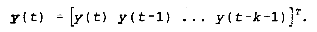
- The received signals for all m antenna elements can now be written as follows:

- The beamformer matrix of
block 202 then constructs r narrow beams, e.g., beams 204, 206 and 208 illustrated inFIG. 3 , which can be described with an r x m matrix B. The output signals generated by thebeamformer 202 are:
- The signals r (t) are the input signals to the radio receiver blocks 220, which signals are converted from RF to baseband. The baseband r(t) signals are then used to estimate the training sequence position and the channel estimate (i.e., the product BH) for each of the r branches at
block 230. Some other quantities, like the signal strength, noise power and C/I, are also estimated for each branch using known techniques. - The training sequence position can, e.g., be estimated by performing a sliding correlation between the received signal and the training sequence. The channel Φ = BH can, e.g., be estimated with a least square estimate,

where R yy is the training sequence correlation matrix and R yr is the cross-correlation between the received signal and the training sequence. - To further reduce the complexity of the receiver, p of r branches are selected at block 240. The selection is made based on one or more of the estimated values in the previous estimation blocks 230, e.g., the estimated C/I. The selection could also be based in part on previously stored estimation values.
- In a first exemplary embodiment, the C/I is used to select the p branches by ordering the r branches according to their estimates of the C/I and to choose the p branches with the highest C/I.
- In another exemplary embodiment, the p + a branches with the highest signal strength (from the estimate of C) are selected first and then from the remaining p + a branches, the p branches with the highest C/I are selected. Here, a is a natural number (i.e., 1, 2, ... , n) such that p + a < r.
- Letting the p x k matrix G consist of the p selected rows of the BH matrix, and letting the
p x 1 vector n (t) consist of the p selected elements of the Bz (t) vector, the p selected signals can then be described as:
- The new channel estimate matrix G contains the p selected row of the previous channel estimate Φ.
- The next step is the estimate the noise cross-correlation matrix:

- This can be done by calculating the sample error cross-correlation matrix:
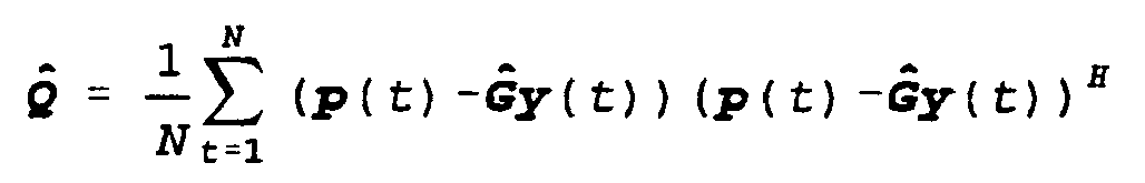
- A significant benefit of the present invention can be seen in the foregoing equations. By selecting only p of the r branches, the vector p becomes smaller. This, in turn, reduces the noise cross-correlation matrix Q, e.g., from an 8x8 matrix to a 3x3 or 4x4 matrix. Since Q may need to be updated very frequently, this results in significant processing reduction. If the noise is Gaussian distributed, then the MLSE solution (Maximum Likelihood Sequence Estimator) can be described as:
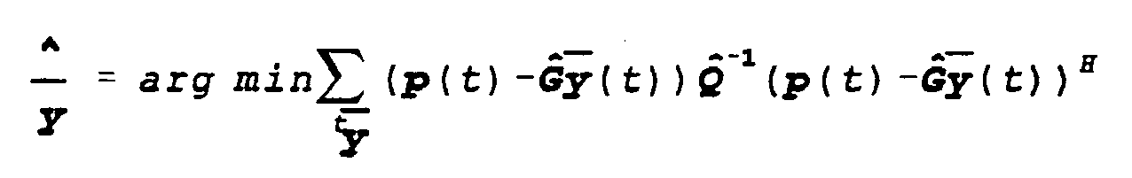
- This can be efficiently implemented using the Viterbi algorithm. Those skilled in the art will be familiar with Viterbi implementations which are not described in further detail here. The metric used in this case will be:

- Exemplary embodiments with two (or more) antenna arrays, e.g., that are shown in
FIG. 4 , can be described using the same mathematical framework as above, but with the difference that the beamforming matrix B now is a block matrix. For example, with two antenna arrays the beamforming matrix B may take the form:
where B1 and B2 can be of different sizes. - Having provided some additional details regarding the signal processing occurring in, for example, blocks 202, 220, 230, 240 and 250 of
FIG. 2 , a brief summary of IRC techniques performed atblock 260 is provided below. For more information the interested reader is referred to the parent IRC applications. IRC techniques expand conventional diversity combining techniques to exploit the above-described correlation, whereby significant gains in the quality of the received signal are realized. The branch metrics Mh(n) formed according to IRC techniques can be described by the following equation.
where: - n is a time index;
- r(n) = [ra(n), rb(n)], are the signal samples received on each antenna;
- C(n) =

are the channel tap estimates of the form Cx(τ) where τ is the delay, i.e., τ=0 is the main ray, τ=1 is the first echo, etc.;
s h(n) = [sh(n), sh(n-1)...]T, are the hypothesized signal samples;
z(n) = [zan), zb(n)]T, are the signal impairments received on each antenna;
A(n) = R zz(n)-1, or a related quantity, where R zz is the impairment correlation matrix which equals the expected value E(z(n)zH(n));
e h(n) = r(n)-C(n)sh(n), is an estimate of the impairment for a given hypothesis. - The A(n) matrix (i.e., the A-matrix) is the inverse of the Rzz(n) matrix, or a related quantity such as the adjoint or pseudo-inverse. As will be apparent to a person skilled in the art reading this application, Rzz(n) and A(n) are specific examples of impairment correlation properties of which other forms are known. Throughout the following, the term A-matrix is used generically to refer to any estimate of the impairment correlation properties.
- Determination of the A-matrix for use in the present invention can be performed in a number of ways depending upon the specific application and the required performance. The simplest approach is to use a fixed set of values for the A-matrix, stored in memory, that are never updated. These values depend primarily on the configuration of the receive antennas and on the carrier frequencies being employed. An alternative approach is to determine the A-matrix from synchronization information and to keep the A-matrix values constant between synchronization fields, or other known fields. At each new occurrence of the synchronization field, the A-matrix can be recomputed, with or without use of the previous A-matrix values. Another alternative approach is to use synchronization fields to initialize, or improve, the A-matrix values and then to use decisions made on the data field symbols to track the A-matrix values.
- Also, consideration is given for the method used to track the A-matrix values. Since the A-matrix comprises information regarding the impairment correlation properties between the antennas in the antenna array, standard estimation methods for estimating correlation or inverse correlation matrices can be applied. Using either known or detected symbol values, impairment values can be obtained by taking the differences between the received signal sample streams and the hypothesized received signal sample streams. At time n, this gives a vector of impairment values, denoted z(n); one value for each antenna. A straightforward way of forming the A-matrix is given by:
- K is a scaling constant, typically 1 or


where:
Because the A-matrix is Hermitian, it is only necessary to compute those elements on the diagonal and either those elements above or below the diagonal.
These techniques for estimating and tracking the A-matrix are given only for purposes of illustration. In general, the A-matrix can be expressed and estimated in a variety of ways, as will be appreciated by a person skilled in the art who is reading this application. The present invention may also be applied to the blind equalization problem in which known synchronization sequences are absent. In this case, the A-matrix is estimated in a manner similar to how the channel is estimated.
Claims (28)
- In a telecommunications system, a base station (130) comprising:an antenna array (200; 400) for receiving a radio signal transmitted from a mobile station (120a-m), wherein said antenna array (200; 400) includes m antenna elements, anda fixed beamforming device (202) coupled to said antenna array (200; 400), wherein said fixed beamforming device (202) receives each of m antenna signals from a corresponding one of said m antenna elements, andwherein said fixed beamforming device (202) combines the m antenna signals to form r beams by multiplying a r x m beamforming matrix B with a vector x(t) comprising the m antenna signals, the r beams covering a cell in which the base station (130) is operating, said base station (130) being further characterized by:a signal quality estimation unit (230) receiving a signal associated with each beam, and deriving therefrom, at least one signal quality measurement for each beam signal,a signal selection unit (240) for selecting two or more of the beam signals based on the signal quality measurement associated with all of the beam signals, anda symbol detection unit receiving the two or more selected beam signals and detecting a sequence of symbols associated with the radio signal received from the mobile station (120a-m), wherein the symbol detection unit combines information provided by the two or more selected beam signals by using a correlation estimate obtained by estimating a correlation between impairment associated with one of the two or more beam signals and impairment associated with another of the two or more selected beam signals.
- The base station (130) of claim 1 further comprising:a second antenna array (402) for receiving the radio signal transmitted from the mobile station (120a-m),wherein the second antenna array (402) includes a second plurality of antenna elements;a second beamforming device coupled to said second antenna array (402), wherein said second fixed beamforming device receives each of a second plurality of antenna signals from a corresponding one of said second plurality of antenna elements, and wherein said second fixed beamforming device combines the second plurality of antenna signals to form a second number of beams covering the cell; anda signal quality estimation unit receiving a signal associated with each of the second number of beams, andderiving therefrom, at least one signal quality measurement for each of the second number of beam signals, said signal selection unit selecting one ormore of the second beam signals based on the signal quality measurement associated with each of the second number of beam signals.
- The base station (130) of claim 2, wherein said first and second antenna array (400, 402) together provide diversity reception.
- The base station (130) of claim 3, wherein said first and second antenna array (400, 402) are spatially separated from each other, and wherein said base station (130) employs spatial diversity.
- The base station (130) of claim 3, wherein said base station (130) employs polarization diversity.
- The base station (130) of claim 1, wherein r, the number of beams formed by said fixed beamforming device (202), is less than m, the number of antenna signals received by said fixed beamforming device (202).
- The base station (130) of claim 1 further comprising:a radio receiver (220) for receiving the signals associated with each of the beams formed by said fixed beamforming device (202) and converting the signals from a radio frequency to a baseband frequency, wherein the signals received by the signal quality estimation unit (230) are at a baseband frequency.
- The base station (130) of claim 1, wherein said signal quality estimation unit (230) comprises:means for deriving at least one signal quality measurement for each beam signal.
- The base station (130) of claim 8, wherein said signal quality estimation unit (230) further comprises:means for locating a training sequence.
- The base station (130) of claim 8, wherein said signal quality estimation unit (230) further comprises:means for estimating a channel impulse response.
- The base station (130) of claim 8, wherein the signal quality measurement is signal strength measurement.
- The base station (130) of claim 8, wherein the signal quality measurement is signal strength to interference ration measurement.
- The base station (130) of claim 1, wherein the number of beam signals selected by said signal selection unit (240) is less than r, the number of beams formed by said fixed beamforming device (202).
- The base station (130) of claim 1, wherein said symbol detection unit comprises:a noise estimator (250); andan interference rejection detector (260).
- The base station (130) of claim 14, wherein said interference rejection detector (260) comprises:means for applying an inverse noise cross-correlation matrix to the sequence of symbols associated with the radio signal received from the mobile station (120a-m).
- The base station (130) of claim 14, wherein said noise estimator (250) comprises:means for deriving a noise cross-correlation matrix.
- The base station (130) of claim 16, wherein said interference rejection detector (260) comprises:means for applying an inverse noise cross-correlation matrix to the sequence of symbols associated with the radio signal received from the mobile station (120a-m).
- The base station (130) of claim 14, wherein said symbol detection unit is a multidimensional maximum likelihood sequence estimation based symbol detection unit.
- In a base station (130) of a telecommunications system, a method for detecting information symbols associated with a received radio signal, said method comprising the steps of:receiving an uplink radio signal using an antenna array (200; 400) which includes m antennas, wherein each antenna generates a received signal from the uplink radio signal, andforming r beams by combining the received m signals by multiplying a r x m beamforming matrix B with a vector x(t) comprising the m signals, wherein the r beams cover a cell supported by the base station (130), said method being further characterized by the steps of:estimating parameters associated with each of the beams,selecting at least two signal processing branches based on the estimated parameters associated with each of the beams, andcombining information provided by the at least two selected signal processing branches to generate detected information symbols, wherein said step of combining includes estimating a correlation between impairment associated with one of the at least two selected signal processing branches and impairment associated with another of the at least two selected signal processing branches and using the correlation estimate to combine at least two received signals.
- The method of claim 19, wherein said step of selecting at least two signal processing branches based on the estimated parameters associated with each of the beams comprises the step of:storing information including previous estimated parameters and selections, andselecting a signal processing branch based on the stored information.
- The method of claim 19, wherein said step of receiving the uplink radio signal using an antenna array (200; 400; which includes m antennas comprises the step of:receiving the uplink radio signal by employing diversity reception.
- The method of claim 21, wherein diversity reception involves polarization diversity.
- The base station (130) of claim 21, wherein diversity reception involves spatial diversity.
- The method of claim 19, wherein the received signals used to define the beams are at a radio frequency.
- The method of claim 19, wherein the signals used to define the beams are at baseband frequency.
- The method of claim 19 further comprising the step of:ordering the beams based on the estimated parameters associated with each of the beams.
- The method of claim 26, wherein said step of ordering the beams based on the estimated parameters associated with each of the beams comprises the step of:ranking the beams based on a signal strength measurement associated with each of the beams.
- The method of claim 26, wherein said step of ordering the beams based on the estimated parameters associated with each of the beams comprises the step of:ranking the beams based on a signal-to-interference ratio measurement associated with each of the beams.
Applications Claiming Priority (3)
| Application Number | Priority Date | Filing Date | Title |
|---|---|---|---|
| US374265 | 1995-01-18 | ||
| US09/374,265 US6470192B1 (en) | 1999-08-16 | 1999-08-16 | Method of an apparatus for beam reduction and combining in a radio communications system |
| PCT/SE2000/001523 WO2001013463A1 (en) | 1999-08-16 | 2000-07-31 | Method of and apparatus for beam reduction and combining in a radio communications system |
Publications (2)
| Publication Number | Publication Date |
|---|---|
| EP1205007A1 EP1205007A1 (en) | 2002-05-15 |
| EP1205007B1 true EP1205007B1 (en) | 2014-03-05 |
Family
ID=23476005
Family Applications (1)
| Application Number | Title | Priority Date | Filing Date |
|---|---|---|---|
| EP00950185.9A Expired - Lifetime EP1205007B1 (en) | 1999-08-16 | 2000-07-31 | Method of and apparatus for beam reduction and combining in a radio communications system |
Country Status (4)
| Country | Link |
|---|---|
| US (1) | US6470192B1 (en) |
| EP (1) | EP1205007B1 (en) |
| AU (1) | AU6332100A (en) |
| WO (1) | WO2001013463A1 (en) |
Families Citing this family (31)
| Publication number | Priority date | Publication date | Assignee | Title |
|---|---|---|---|---|
| US6278726B1 (en) * | 1999-09-10 | 2001-08-21 | Interdigital Technology Corporation | Interference cancellation in a spread spectrum communication system |
| US6115406A (en) * | 1999-09-10 | 2000-09-05 | Interdigital Technology Corporation | Transmission using an antenna array in a CDMA communication system |
| US7027536B1 (en) * | 1999-10-08 | 2006-04-11 | At&T Corp. | Method and apparatus for designing finite-length multi-input multi-output channel shortening pre-filters |
| US6754511B1 (en) * | 2000-02-04 | 2004-06-22 | Harris Corporation | Linear signal separation using polarization diversity |
| FI20001160A7 (en) * | 2000-05-15 | 2001-11-16 | Nokia Corp | Pilot signal implementation method |
| SE521246C2 (en) * | 2001-06-12 | 2003-10-14 | Ericsson Telefon Ab L M | blind Detection |
| FR2826526B1 (en) * | 2001-06-21 | 2003-10-24 | France Telecom | REDUCED INTERFERENCE TRANSMISSION METHOD |
| GB2384651B (en) * | 2002-01-28 | 2004-03-24 | Toshiba Res Europ Ltd | Signal selection systems |
| US6850741B2 (en) * | 2002-04-04 | 2005-02-01 | Agency For Science, Technology And Research | Method for selecting switched orthogonal beams for downlink diversity transmission |
| JP2003338804A (en) * | 2002-05-22 | 2003-11-28 | Nec Corp | Path search apparatus and method, and antenna array receiving apparatus using the same |
| US20040116122A1 (en) * | 2002-09-20 | 2004-06-17 | Interdigital Technology Corporation | Enhancing reception using intercellular interference cancellation |
| AU2003274529A1 (en) * | 2002-11-26 | 2004-06-18 | Koninklijke Philips Electronics N.V. | Apparatus, module and computer program for minimizing correlation between received signals |
| US6920193B2 (en) * | 2002-12-19 | 2005-07-19 | Texas Instruments Incorporated | Wireless receiver using noise levels for combining signals having spatial diversity |
| JP4091854B2 (en) * | 2003-01-31 | 2008-05-28 | 富士通株式会社 | Array antenna control method and apparatus, and array antenna control program |
| US6992621B2 (en) * | 2003-03-07 | 2006-01-31 | Vivato, Inc. | Wireless communication and beam forming with passive beamformers |
| US7437135B2 (en) | 2003-10-30 | 2008-10-14 | Interdigital Technology Corporation | Joint channel equalizer interference canceller advanced receiver |
| US7400692B2 (en) | 2004-01-14 | 2008-07-15 | Interdigital Technology Corporation | Telescoping window based equalization |
| ZA200608087B (en) * | 2004-05-28 | 2008-03-26 | Ericsson Telefon Ab L M | A digitizer arrangement |
| US8542589B2 (en) * | 2006-06-05 | 2013-09-24 | Qualcomm Incorporated | Method and apparatus for providing beamforming feedback in wireless communication systems |
| CN101291165B (en) * | 2007-04-17 | 2012-11-14 | 电信科学技术研究院 | Sequence detecting method and apparatus for multi-antenna system |
| CN101316130B (en) * | 2007-06-01 | 2014-06-11 | 中国移动通信集团公司 | Community antenna system and method in closed loop mode |
| KR101513889B1 (en) * | 2008-02-14 | 2015-05-20 | 삼성전자주식회사 | Apparatus and method for switched beam-forming using multi-beam combining |
| US8666004B2 (en) * | 2008-05-21 | 2014-03-04 | Qualcomm Incorporated | Methods and systems for hybrid MIMO schemes in OFDM/A systems |
| GB2479549B (en) * | 2010-04-13 | 2012-10-03 | Toshiba Res Europ Ltd | Low complexity antenna selection methods for interference rejection receivers |
| US10784904B2 (en) * | 2015-02-23 | 2020-09-22 | Qualcomm Incorporated | Transceiver configuration for millimeter wave wireless communications |
| KR102109918B1 (en) * | 2015-06-15 | 2020-05-12 | 삼성전자주식회사 | Apparatus and method for beamforming using antenna array in wireless communication system |
| EP3568921A1 (en) * | 2017-01-16 | 2019-11-20 | Telefonaktiebolaget LM Ericsson (publ) | A transceiver arrangement |
| CN111339484B (en) * | 2020-02-20 | 2022-07-01 | 中国科学院自动化研究所 | Implementation method and device of large-scale radio interference array correlator based on FPGA |
| US11606762B2 (en) * | 2020-07-17 | 2023-03-14 | Qualcomm Incorporated | Synchronization signal block-level sleep mode |
| WO2022162739A1 (en) * | 2021-01-26 | 2022-08-04 | 日本電信電話株式会社 | Communication path estimation method and wireless communication device |
| JP7513123B2 (en) * | 2021-01-26 | 2024-07-09 | 日本電信電話株式会社 | Communication channel estimation method and wireless communication device |
Citations (1)
| Publication number | Priority date | Publication date | Assignee | Title |
|---|---|---|---|---|
| EP0883208A2 (en) * | 1997-06-05 | 1998-12-09 | Nortel Networks Corporation | Multi-beam antenna system for cellular radio base stations |
Family Cites Families (26)
| Publication number | Priority date | Publication date | Assignee | Title |
|---|---|---|---|---|
| US4713817A (en) | 1985-04-25 | 1987-12-15 | Codex Corporation | Multidimensional, convolutionally coded communication systems |
| DE3517247A1 (en) | 1985-05-13 | 1986-11-13 | Gerhard Prof. Dr.-Ing. 8012 Ottobrunn Flachenecker | ANTENNA DIVERSITY RECEIVING SYSTEM FOR ELIMINATION OF RECEIVING ERRORS |
| US4644562A (en) | 1985-08-28 | 1987-02-17 | At&T Company | Combined cross polarization interference cancellation and intersymbol interference equalization for terrestrial digital radio systems |
| DE3836046A1 (en) | 1987-10-31 | 1989-05-11 | Hirschmann Radiotechnik | RECEIVING METHOD AND RECEIVING ANTENNA SYSTEM FOR CARRYING OUT THE METHOD |
| CA1338153C (en) | 1987-11-10 | 1996-03-12 | Yoshihiro Nozue | Interference canceller |
| SE463540B (en) | 1988-09-19 | 1990-12-03 | Ericsson Telefon Ab L M | SEAT TO DIGITALIZE ANY RADIO SIGNALS IN A RADIO COMMUNICATION SYSTEM AND DEVICE TO EXERCISE THE SET |
| EP0381949A1 (en) | 1989-02-01 | 1990-08-16 | Siemens Aktiengesellschaft | Diversity combiner |
| SE464902B (en) | 1989-10-24 | 1991-06-24 | Ericsson Telefon Ab L M | PROCEDURE TO ADAPT A VITERBIAL ALGORITHM TO A CHANNEL WITH VARIOUS TRANSFER PROPERTIES AND A DEVICE IMPLEMENTING PROCEDURE |
| US5031193A (en) | 1989-11-13 | 1991-07-09 | Motorola, Inc. | Method and apparatus for diversity reception of time-dispersed signals |
| SE465597B (en) | 1990-02-16 | 1991-09-30 | Ericsson Telefon Ab L M | PROCEDURE TO REDUCE THE EFFECT OF BREATHING ON A WHITE RECEIVER WITH AT LEAST TWO ANTENNA |
| GB2270236B (en) | 1991-02-22 | 1995-06-21 | Motorola Inc | Method of operating a communications system |
| EP0543328B1 (en) | 1991-11-18 | 1999-03-17 | Nec Corporation | Automatic equalizer capable of effectively cancelling intersymbol interference and cross polarization interference in co-channel dual polarization |
| US5515378A (en) | 1991-12-12 | 1996-05-07 | Arraycomm, Inc. | Spatial division multiple access wireless communication systems |
| US5319677A (en) | 1992-05-12 | 1994-06-07 | Hughes Aircraft Company | Diversity combiner with MLSE for digital cellular radio |
| JP2982504B2 (en) | 1992-07-31 | 1999-11-22 | 日本電気株式会社 | Adaptive receiver |
| GB9309353D0 (en) | 1993-05-06 | 1993-06-16 | Ncr Int Inc | Wireless communication system having antenna diversity |
| US5487091A (en) | 1993-08-13 | 1996-01-23 | Motorola, Inc. | Method for determining signal usability in a diversity receiver |
| US5351274A (en) | 1993-08-20 | 1994-09-27 | General Electric Company | Post detection selection combining diversity receivers for mobile and indoor radio channels |
| NZ264830A (en) | 1993-11-15 | 1996-11-26 | Alcatel Australia | Extending the range of a time division multiple access cellular communication system |
| RU2183906C2 (en) | 1994-06-03 | 2002-06-20 | Телефонактиеболагет Лм Эрикссон | Diversity reception with addition in antennas |
| US6081566A (en) | 1994-08-02 | 2000-06-27 | Ericsson, Inc. | Method and apparatus for interference rejection with different beams, polarizations, and phase references |
| US5481572A (en) | 1994-08-02 | 1996-01-02 | Ericsson Inc. | Method of and apparatus for reducing the complexitiy of a diversity combining and sequence estimation receiver |
| US5680419A (en) | 1994-08-02 | 1997-10-21 | Ericsson Inc. | Method of and apparatus for interference rejection combining in multi-antenna digital cellular communications systems |
| US5684491A (en) | 1995-01-27 | 1997-11-04 | Hazeltine Corporation | High gain antenna systems for cellular use |
| US5924020A (en) * | 1995-12-15 | 1999-07-13 | Telefonaktiebolaget L M Ericsson (Publ) | Antenna assembly and associated method for radio communication device |
| IT1285217B1 (en) | 1996-07-04 | 1998-06-03 | Italtel Spa | METHOD FOR THE AUTOMATIC SELECTION OF A BEAM AMONG THOSE FORMED BY A MULTI BEAM ANTENNA, PARTICULARLY FOR MOBILE RADIO SYSTEMS |
-
1999
- 1999-08-16 US US09/374,265 patent/US6470192B1/en not_active Expired - Lifetime
-
2000
- 2000-07-31 WO PCT/SE2000/001523 patent/WO2001013463A1/en not_active Ceased
- 2000-07-31 EP EP00950185.9A patent/EP1205007B1/en not_active Expired - Lifetime
- 2000-07-31 AU AU63321/00A patent/AU6332100A/en not_active Abandoned
Patent Citations (1)
| Publication number | Priority date | Publication date | Assignee | Title |
|---|---|---|---|---|
| EP0883208A2 (en) * | 1997-06-05 | 1998-12-09 | Nortel Networks Corporation | Multi-beam antenna system for cellular radio base stations |
Also Published As
| Publication number | Publication date |
|---|---|
| AU6332100A (en) | 2001-03-13 |
| EP1205007A1 (en) | 2002-05-15 |
| WO2001013463A1 (en) | 2001-02-22 |
| US6470192B1 (en) | 2002-10-22 |
Similar Documents
| Publication | Publication Date | Title |
|---|---|---|
| EP1205007B1 (en) | Method of and apparatus for beam reduction and combining in a radio communications system | |
| US6173014B1 (en) | Method of and apparatus for interference rejection combining and downlink beamforming in a cellular radio communications system | |
| US6314147B1 (en) | Two-stage CCI/ISI reduction with space-time processing in TDMA cellular networks | |
| US6081566A (en) | Method and apparatus for interference rejection with different beams, polarizations, and phase references | |
| EP1667341B1 (en) | Method for calculating a weighting vector for an antenna array | |
| US6128355A (en) | Selective diversity combining | |
| US7411547B2 (en) | Antenna array including virtual antenna elements | |
| US7949304B2 (en) | Interference cancellation and receive diversity for single-valued modulation receivers | |
| US5875216A (en) | Weight generation in stationary interference and noise environments | |
| CN100420166C (en) | Array receiver with subarray selection, method of use and receiver system incorporating same | |
| TWI479827B (en) | Wireless receiver with receive diversity | |
| EP1499037A1 (en) | Apparatus and method for receiving data in a mobile communication system using an adaptive antenna array scheme | |
| EP0477183B1 (en) | Space-diversity digital radio mobile receiver and relevant process | |
| EP1494368A2 (en) | Receiver with adaptive antenna array | |
| EP1336261B1 (en) | Determinant-based synchronization techniques and systems | |
| JP2823829B2 (en) | Wireless communication system and wireless receiver | |
| Grotz et al. | Signal detection and synchronization for interference overloaded satellite broadcast reception | |
| Chandrasekaran et al. | A modified sequential beamforming algorithm for cochannel IS-136 signals | |
| Winters | Smart antennas for the EDGE wireless TDMA system | |
| Zheng et al. | Adaptive arrays for broadband communications in the presence of unknown co-channel interference | |
| CRISAN et al. | Multiple-Input Adaptive Combiner-Equalizer for Wireless Communications | |
| Yoshii et al. | Adaptive spatial and temporal optimal receiver using adaptive array antenna |
Legal Events
| Date | Code | Title | Description |
|---|---|---|---|
| PUAI | Public reference made under article 153(3) epc to a published international application that has entered the european phase |
Free format text: ORIGINAL CODE: 0009012 |
|
| 17P | Request for examination filed |
Effective date: 20020226 |
|
| AK | Designated contracting states |
Kind code of ref document: A1 Designated state(s): AT BE CH CY DE DK ES FI FR GB GR IE IT LI LU MC NL PT SE |
|
| AX | Request for extension of the european patent |
Free format text: AL;LT;LV;MK;RO;SI |
|
| RAP1 | Party data changed (applicant data changed or rights of an application transferred) |
Owner name: TELEFONAKTIEBOLAGET LM ERICSSON (PUBL) |
|
| 17Q | First examination report despatched |
Effective date: 20061227 |
|
| RIC1 | Information provided on ipc code assigned before grant |
Ipc: H04B 7/08 20060101ALI20130725BHEP Ipc: H04B 7/10 20060101ALI20130725BHEP Ipc: H04W 16/28 20090101ALI20130725BHEP Ipc: H01Q 3/24 20060101AFI20130725BHEP Ipc: H01Q 1/24 20060101ALI20130725BHEP Ipc: H01Q 3/26 20060101ALI20130725BHEP |
|
| GRAP | Despatch of communication of intention to grant a patent |
Free format text: ORIGINAL CODE: EPIDOSNIGR1 |
|
| INTG | Intention to grant announced |
Effective date: 20130918 |
|
| GRAS | Grant fee paid |
Free format text: ORIGINAL CODE: EPIDOSNIGR3 |
|
| GRAA | (expected) grant |
Free format text: ORIGINAL CODE: 0009210 |
|
| AK | Designated contracting states |
Kind code of ref document: B1 Designated state(s): AT BE CH CY DE DK ES FI FR GB GR IE IT LI LU MC NL PT SE |
|
| REG | Reference to a national code |
Ref country code: GB Ref legal event code: FG4D |
|
| REG | Reference to a national code |
Ref country code: CH Ref legal event code: EP |
|
| REG | Reference to a national code |
Ref country code: AT Ref legal event code: REF Ref document number: 655415 Country of ref document: AT Kind code of ref document: T Effective date: 20140315 |
|
| REG | Reference to a national code |
Ref country code: IE Ref legal event code: FG4D |
|
| REG | Reference to a national code |
Ref country code: DE Ref legal event code: R096 Ref document number: 60048458 Country of ref document: DE Effective date: 20140417 |
|
| REG | Reference to a national code |
Ref country code: NL Ref legal event code: T3 |
|
| REG | Reference to a national code |
Ref country code: SE Ref legal event code: TRGR |
|
| REG | Reference to a national code |
Ref country code: AT Ref legal event code: MK05 Ref document number: 655415 Country of ref document: AT Kind code of ref document: T Effective date: 20140305 |
|
| PG25 | Lapsed in a contracting state [announced via postgrant information from national office to epo] |
Ref country code: AT Free format text: LAPSE BECAUSE OF FAILURE TO SUBMIT A TRANSLATION OF THE DESCRIPTION OR TO PAY THE FEE WITHIN THE PRESCRIBED TIME-LIMIT Effective date: 20140305 Ref country code: FI Free format text: LAPSE BECAUSE OF FAILURE TO SUBMIT A TRANSLATION OF THE DESCRIPTION OR TO PAY THE FEE WITHIN THE PRESCRIBED TIME-LIMIT Effective date: 20140305 |
|
| PG25 | Lapsed in a contracting state [announced via postgrant information from national office to epo] |
Ref country code: BE Free format text: LAPSE BECAUSE OF FAILURE TO SUBMIT A TRANSLATION OF THE DESCRIPTION OR TO PAY THE FEE WITHIN THE PRESCRIBED TIME-LIMIT Effective date: 20140305 |
|
| RAP2 | Party data changed (patent owner data changed or rights of a patent transferred) |
Owner name: OPTIS CELLULAR TECHNOLOGY, LLC |
|
| PG25 | Lapsed in a contracting state [announced via postgrant information from national office to epo] |
Ref country code: ES Free format text: LAPSE BECAUSE OF FAILURE TO SUBMIT A TRANSLATION OF THE DESCRIPTION OR TO PAY THE FEE WITHIN THE PRESCRIBED TIME-LIMIT Effective date: 20140305 |
|
| REG | Reference to a national code |
Ref country code: DE Ref legal event code: R097 Ref document number: 60048458 Country of ref document: DE |
|
| PG25 | Lapsed in a contracting state [announced via postgrant information from national office to epo] |
Ref country code: PT Free format text: LAPSE BECAUSE OF FAILURE TO SUBMIT A TRANSLATION OF THE DESCRIPTION OR TO PAY THE FEE WITHIN THE PRESCRIBED TIME-LIMIT Effective date: 20140707 |
|
| PLBE | No opposition filed within time limit |
Free format text: ORIGINAL CODE: 0009261 |
|
| STAA | Information on the status of an ep patent application or granted ep patent |
Free format text: STATUS: NO OPPOSITION FILED WITHIN TIME LIMIT |
|
| REG | Reference to a national code |
Ref country code: DE Ref legal event code: R082 Ref document number: 60048458 Country of ref document: DE Representative=s name: GRUENECKER, KINKELDEY, STOCKMAIR & SCHWANHAEUS, DE |
|
| PG25 | Lapsed in a contracting state [announced via postgrant information from national office to epo] |
Ref country code: DK Free format text: LAPSE BECAUSE OF FAILURE TO SUBMIT A TRANSLATION OF THE DESCRIPTION OR TO PAY THE FEE WITHIN THE PRESCRIBED TIME-LIMIT Effective date: 20140305 |
|
| 26N | No opposition filed |
Effective date: 20141208 |
|
| REG | Reference to a national code |
Ref country code: DE Ref legal event code: R081 Ref document number: 60048458 Country of ref document: DE Owner name: OPTIS CELLULAR TECHNOLOGY, LLC (N. D. GES. D. , US Free format text: FORMER OWNER: TELEFONAKTIEBOLAGET LM ERICSSON (PUBL), STOCKHOLM, SE Effective date: 20150119 Ref country code: DE Ref legal event code: R081 Ref document number: 60048458 Country of ref document: DE Owner name: OPTIS CELLULAR TECHNOLOGY, LLC (N. D. GES. D. , US Free format text: FORMER OWNER: TELEFONAKTIEBOLAGET LM ERICSSON (PUBL), STOCKHOLM, SE Effective date: 20140306 Ref country code: DE Ref legal event code: R082 Ref document number: 60048458 Country of ref document: DE Representative=s name: GRUENECKER, KINKELDEY, STOCKMAIR & SCHWANHAEUS, DE Effective date: 20150119 Ref country code: DE Ref legal event code: R082 Ref document number: 60048458 Country of ref document: DE Representative=s name: GRUENECKER PATENT- UND RECHTSANWAELTE PARTG MB, DE Effective date: 20150119 |
|
| PG25 | Lapsed in a contracting state [announced via postgrant information from national office to epo] |
Ref country code: LU Free format text: LAPSE BECAUSE OF FAILURE TO SUBMIT A TRANSLATION OF THE DESCRIPTION OR TO PAY THE FEE WITHIN THE PRESCRIBED TIME-LIMIT Effective date: 20140731 |
|
| REG | Reference to a national code |
Ref country code: CH Ref legal event code: PL |
|
| REG | Reference to a national code |
Ref country code: DE Ref legal event code: R097 Ref document number: 60048458 Country of ref document: DE Effective date: 20141208 |
|
| PG25 | Lapsed in a contracting state [announced via postgrant information from national office to epo] |
Ref country code: IT Free format text: LAPSE BECAUSE OF FAILURE TO SUBMIT A TRANSLATION OF THE DESCRIPTION OR TO PAY THE FEE WITHIN THE PRESCRIBED TIME-LIMIT Effective date: 20140305 |
|
| REG | Reference to a national code |
Ref country code: IE Ref legal event code: MM4A |
|
| REG | Reference to a national code |
Ref country code: FR Ref legal event code: ST Effective date: 20150331 |
|
| PG25 | Lapsed in a contracting state [announced via postgrant information from national office to epo] |
Ref country code: CH Free format text: LAPSE BECAUSE OF NON-PAYMENT OF DUE FEES Effective date: 20140731 Ref country code: LI Free format text: LAPSE BECAUSE OF NON-PAYMENT OF DUE FEES Effective date: 20140731 |
|
| PG25 | Lapsed in a contracting state [announced via postgrant information from national office to epo] |
Ref country code: FR Free format text: LAPSE BECAUSE OF NON-PAYMENT OF DUE FEES Effective date: 20140731 |
|
| REG | Reference to a national code |
Ref country code: NL Ref legal event code: SD Effective date: 20150630 |
|
| PG25 | Lapsed in a contracting state [announced via postgrant information from national office to epo] |
Ref country code: IE Free format text: LAPSE BECAUSE OF NON-PAYMENT OF DUE FEES Effective date: 20140731 |
|
| PG25 | Lapsed in a contracting state [announced via postgrant information from national office to epo] |
Ref country code: MC Free format text: LAPSE BECAUSE OF FAILURE TO SUBMIT A TRANSLATION OF THE DESCRIPTION OR TO PAY THE FEE WITHIN THE PRESCRIBED TIME-LIMIT Effective date: 20140305 |
|
| PG25 | Lapsed in a contracting state [announced via postgrant information from national office to epo] |
Ref country code: CY Free format text: LAPSE BECAUSE OF FAILURE TO SUBMIT A TRANSLATION OF THE DESCRIPTION OR TO PAY THE FEE WITHIN THE PRESCRIBED TIME-LIMIT Effective date: 20140305 Ref country code: GR Free format text: LAPSE BECAUSE OF FAILURE TO SUBMIT A TRANSLATION OF THE DESCRIPTION OR TO PAY THE FEE WITHIN THE PRESCRIBED TIME-LIMIT Effective date: 20140606 |
|
| PGFP | Annual fee paid to national office [announced via postgrant information from national office to epo] |
Ref country code: GB Payment date: 20160627 Year of fee payment: 17 |
|
| PGFP | Annual fee paid to national office [announced via postgrant information from national office to epo] |
Ref country code: NL Payment date: 20160623 Year of fee payment: 17 Ref country code: SE Payment date: 20160627 Year of fee payment: 17 |
|
| PGFP | Annual fee paid to national office [announced via postgrant information from national office to epo] |
Ref country code: DE Payment date: 20160622 Year of fee payment: 17 |
|
| REG | Reference to a national code |
Ref country code: GB Ref legal event code: 732E Free format text: REGISTERED BETWEEN 20161020 AND 20161026 |
|
| REG | Reference to a national code |
Ref country code: DE Ref legal event code: R119 Ref document number: 60048458 Country of ref document: DE |
|
| REG | Reference to a national code |
Ref country code: NL Ref legal event code: MM Effective date: 20170801 |
|
| GBPC | Gb: european patent ceased through non-payment of renewal fee |
Effective date: 20170731 |
|
| PG25 | Lapsed in a contracting state [announced via postgrant information from national office to epo] |
Ref country code: NL Free format text: LAPSE BECAUSE OF NON-PAYMENT OF DUE FEES Effective date: 20170801 Ref country code: GB Free format text: LAPSE BECAUSE OF NON-PAYMENT OF DUE FEES Effective date: 20170731 Ref country code: DE Free format text: LAPSE BECAUSE OF NON-PAYMENT OF DUE FEES Effective date: 20180201 Ref country code: SE Free format text: LAPSE BECAUSE OF NON-PAYMENT OF DUE FEES Effective date: 20170801 |