EP1204456B1 - Modular pressure swing adsorption apparatus - Google Patents
Modular pressure swing adsorption apparatus Download PDFInfo
- Publication number
- EP1204456B1 EP1204456B1 EP00941816A EP00941816A EP1204456B1 EP 1204456 B1 EP1204456 B1 EP 1204456B1 EP 00941816 A EP00941816 A EP 00941816A EP 00941816 A EP00941816 A EP 00941816A EP 1204456 B1 EP1204456 B1 EP 1204456B1
- Authority
- EP
- European Patent Office
- Prior art keywords
- pressure
- face
- rotor
- compartment
- stator
- Prior art date
- Legal status (The legal status is an assumption and is not a legal conclusion. Google has not performed a legal analysis and makes no representation as to the accuracy of the status listed.)
- Expired - Lifetime
Links
- 238000001179 sorption measurement Methods 0.000 title claims abstract description 12
- 238000007789 sealing Methods 0.000 claims abstract description 154
- 230000007704 transition Effects 0.000 claims abstract description 31
- 239000003463 adsorbent Substances 0.000 claims abstract description 25
- 239000000463 material Substances 0.000 claims abstract description 10
- 230000004044 response Effects 0.000 claims abstract description 9
- 238000000034 method Methods 0.000 claims abstract description 8
- 230000008569 process Effects 0.000 claims abstract description 8
- 239000000203 mixture Substances 0.000 claims description 12
- 238000004891 communication Methods 0.000 claims description 10
- 230000008878 coupling Effects 0.000 claims description 5
- 238000010168 coupling process Methods 0.000 claims description 5
- 238000005859 coupling reaction Methods 0.000 claims description 5
- 230000001351 cycling effect Effects 0.000 claims description 2
- 238000000926 separation method Methods 0.000 abstract description 11
- 238000012546 transfer Methods 0.000 abstract description 4
- 239000007789 gas Substances 0.000 description 132
- 238000010992 reflux Methods 0.000 description 131
- 230000006835 compression Effects 0.000 description 13
- 238000007906 compression Methods 0.000 description 13
- 230000002829 reductive effect Effects 0.000 description 8
- IJGRMHOSHXDMSA-UHFFFAOYSA-N Atomic nitrogen Chemical compound N#N IJGRMHOSHXDMSA-UHFFFAOYSA-N 0.000 description 7
- 238000013459 approach Methods 0.000 description 7
- QVGXLLKOCUKJST-UHFFFAOYSA-N atomic oxygen Chemical compound [O] QVGXLLKOCUKJST-UHFFFAOYSA-N 0.000 description 7
- 238000011068 loading method Methods 0.000 description 7
- 239000001301 oxygen Substances 0.000 description 7
- 229910052760 oxygen Inorganic materials 0.000 description 7
- 239000012530 fluid Substances 0.000 description 6
- 238000011064 split stream procedure Methods 0.000 description 6
- 230000003068 static effect Effects 0.000 description 6
- 238000009826 distribution Methods 0.000 description 5
- 238000004519 manufacturing process Methods 0.000 description 5
- 238000011084 recovery Methods 0.000 description 5
- 229910052757 nitrogen Inorganic materials 0.000 description 4
- 230000008859 change Effects 0.000 description 3
- 238000013461 design Methods 0.000 description 3
- 239000004810 polytetrafluoroethylene Substances 0.000 description 3
- 229920001343 polytetrafluoroethylene Polymers 0.000 description 3
- 238000010926 purge Methods 0.000 description 3
- 230000001172 regenerating effect Effects 0.000 description 3
- 239000000725 suspension Substances 0.000 description 3
- XLYOFNOQVPJJNP-UHFFFAOYSA-N water Substances O XLYOFNOQVPJJNP-UHFFFAOYSA-N 0.000 description 3
- OKTJSMMVPCPJKN-UHFFFAOYSA-N Carbon Chemical compound [C] OKTJSMMVPCPJKN-UHFFFAOYSA-N 0.000 description 2
- 239000002131 composite material Substances 0.000 description 2
- 230000007423 decrease Effects 0.000 description 2
- 230000001419 dependent effect Effects 0.000 description 2
- 238000010586 diagram Methods 0.000 description 2
- 238000002156 mixing Methods 0.000 description 2
- 230000010349 pulsation Effects 0.000 description 2
- 238000013517 stratification Methods 0.000 description 2
- 238000012935 Averaging Methods 0.000 description 1
- 229910021536 Zeolite Inorganic materials 0.000 description 1
- 239000006096 absorbing agent Substances 0.000 description 1
- 230000001133 acceleration Effects 0.000 description 1
- 238000004887 air purification Methods 0.000 description 1
- 230000003190 augmentative effect Effects 0.000 description 1
- 230000008901 benefit Effects 0.000 description 1
- UQMRAFJOBWOFNS-UHFFFAOYSA-N butyl 2-(2,4-dichlorophenoxy)acetate Chemical compound CCCCOC(=O)COC1=CC=C(Cl)C=C1Cl UQMRAFJOBWOFNS-UHFFFAOYSA-N 0.000 description 1
- 229910052799 carbon Inorganic materials 0.000 description 1
- 150000001875 compounds Chemical class 0.000 description 1
- 238000010276 construction Methods 0.000 description 1
- 238000011109 contamination Methods 0.000 description 1
- 125000004122 cyclic group Chemical group 0.000 description 1
- 230000007812 deficiency Effects 0.000 description 1
- HNPSIPDUKPIQMN-UHFFFAOYSA-N dioxosilane;oxo(oxoalumanyloxy)alumane Chemical compound O=[Si]=O.O=[Al]O[Al]=O HNPSIPDUKPIQMN-UHFFFAOYSA-N 0.000 description 1
- 239000006185 dispersion Substances 0.000 description 1
- 239000000806 elastomer Substances 0.000 description 1
- 229920001971 elastomer Polymers 0.000 description 1
- 230000002349 favourable effect Effects 0.000 description 1
- 239000000835 fiber Substances 0.000 description 1
- 239000011888 foil Substances 0.000 description 1
- 239000010439 graphite Substances 0.000 description 1
- 229910002804 graphite Inorganic materials 0.000 description 1
- 238000010438 heat treatment Methods 0.000 description 1
- 238000009434 installation Methods 0.000 description 1
- 230000002427 irreversible effect Effects 0.000 description 1
- 230000000670 limiting effect Effects 0.000 description 1
- 239000002184 metal Substances 0.000 description 1
- QJGQUHMNIGDVPM-UHFFFAOYSA-N nitrogen group Chemical group [N] QJGQUHMNIGDVPM-UHFFFAOYSA-N 0.000 description 1
- 238000012856 packing Methods 0.000 description 1
- 230000036961 partial effect Effects 0.000 description 1
- 238000005192 partition Methods 0.000 description 1
- 230000021715 photosynthesis, light harvesting Effects 0.000 description 1
- 230000036316 preload Effects 0.000 description 1
- 239000007787 solid Substances 0.000 description 1
- 239000011343 solid material Substances 0.000 description 1
- 230000006641 stabilisation Effects 0.000 description 1
- 238000011105 stabilization Methods 0.000 description 1
- 229920001169 thermoplastic Polymers 0.000 description 1
- 239000004416 thermosoftening plastic Substances 0.000 description 1
- 238000011144 upstream manufacturing Methods 0.000 description 1
- 239000002699 waste material Substances 0.000 description 1
- 239000010457 zeolite Substances 0.000 description 1
Images





Classifications
-
- B—PERFORMING OPERATIONS; TRANSPORTING
- B01—PHYSICAL OR CHEMICAL PROCESSES OR APPARATUS IN GENERAL
- B01D—SEPARATION
- B01D53/00—Separation of gases or vapours; Recovering vapours of volatile solvents from gases; Chemical or biological purification of waste gases, e.g. engine exhaust gases, smoke, fumes, flue gases, aerosols
- B01D53/02—Separation of gases or vapours; Recovering vapours of volatile solvents from gases; Chemical or biological purification of waste gases, e.g. engine exhaust gases, smoke, fumes, flue gases, aerosols by adsorption, e.g. preparative gas chromatography
- B01D53/04—Separation of gases or vapours; Recovering vapours of volatile solvents from gases; Chemical or biological purification of waste gases, e.g. engine exhaust gases, smoke, fumes, flue gases, aerosols by adsorption, e.g. preparative gas chromatography with stationary adsorbents
- B01D53/0407—Constructional details of adsorbing systems
- B01D53/0431—Beds with radial gas flow
-
- B—PERFORMING OPERATIONS; TRANSPORTING
- B01—PHYSICAL OR CHEMICAL PROCESSES OR APPARATUS IN GENERAL
- B01D—SEPARATION
- B01D53/00—Separation of gases or vapours; Recovering vapours of volatile solvents from gases; Chemical or biological purification of waste gases, e.g. engine exhaust gases, smoke, fumes, flue gases, aerosols
- B01D53/02—Separation of gases or vapours; Recovering vapours of volatile solvents from gases; Chemical or biological purification of waste gases, e.g. engine exhaust gases, smoke, fumes, flue gases, aerosols by adsorption, e.g. preparative gas chromatography
- B01D53/04—Separation of gases or vapours; Recovering vapours of volatile solvents from gases; Chemical or biological purification of waste gases, e.g. engine exhaust gases, smoke, fumes, flue gases, aerosols by adsorption, e.g. preparative gas chromatography with stationary adsorbents
- B01D53/0454—Controlling adsorption
-
- B—PERFORMING OPERATIONS; TRANSPORTING
- B01—PHYSICAL OR CHEMICAL PROCESSES OR APPARATUS IN GENERAL
- B01D—SEPARATION
- B01D53/00—Separation of gases or vapours; Recovering vapours of volatile solvents from gases; Chemical or biological purification of waste gases, e.g. engine exhaust gases, smoke, fumes, flue gases, aerosols
- B01D53/02—Separation of gases or vapours; Recovering vapours of volatile solvents from gases; Chemical or biological purification of waste gases, e.g. engine exhaust gases, smoke, fumes, flue gases, aerosols by adsorption, e.g. preparative gas chromatography
- B01D53/06—Separation of gases or vapours; Recovering vapours of volatile solvents from gases; Chemical or biological purification of waste gases, e.g. engine exhaust gases, smoke, fumes, flue gases, aerosols by adsorption, e.g. preparative gas chromatography with moving adsorbents, e.g. rotating beds
-
- B—PERFORMING OPERATIONS; TRANSPORTING
- B01—PHYSICAL OR CHEMICAL PROCESSES OR APPARATUS IN GENERAL
- B01D—SEPARATION
- B01D2253/00—Adsorbents used in seperation treatment of gases and vapours
- B01D2253/10—Inorganic adsorbents
- B01D2253/106—Silica or silicates
- B01D2253/108—Zeolites
-
- B—PERFORMING OPERATIONS; TRANSPORTING
- B01—PHYSICAL OR CHEMICAL PROCESSES OR APPARATUS IN GENERAL
- B01D—SEPARATION
- B01D2256/00—Main component in the product gas stream after treatment
- B01D2256/16—Hydrogen
-
- B—PERFORMING OPERATIONS; TRANSPORTING
- B01—PHYSICAL OR CHEMICAL PROCESSES OR APPARATUS IN GENERAL
- B01D—SEPARATION
- B01D2257/00—Components to be removed
- B01D2257/10—Single element gases other than halogens
- B01D2257/102—Nitrogen
-
- B—PERFORMING OPERATIONS; TRANSPORTING
- B01—PHYSICAL OR CHEMICAL PROCESSES OR APPARATUS IN GENERAL
- B01D—SEPARATION
- B01D2259/00—Type of treatment
- B01D2259/40—Further details for adsorption processes and devices
- B01D2259/40003—Methods relating to valve switching
- B01D2259/40005—Methods relating to valve switching using rotary valves
-
- B—PERFORMING OPERATIONS; TRANSPORTING
- B01—PHYSICAL OR CHEMICAL PROCESSES OR APPARATUS IN GENERAL
- B01D—SEPARATION
- B01D53/00—Separation of gases or vapours; Recovering vapours of volatile solvents from gases; Chemical or biological purification of waste gases, e.g. engine exhaust gases, smoke, fumes, flue gases, aerosols
- B01D53/02—Separation of gases or vapours; Recovering vapours of volatile solvents from gases; Chemical or biological purification of waste gases, e.g. engine exhaust gases, smoke, fumes, flue gases, aerosols by adsorption, e.g. preparative gas chromatography
- B01D53/04—Separation of gases or vapours; Recovering vapours of volatile solvents from gases; Chemical or biological purification of waste gases, e.g. engine exhaust gases, smoke, fumes, flue gases, aerosols by adsorption, e.g. preparative gas chromatography with stationary adsorbents
- B01D53/047—Pressure swing adsorption
- B01D53/0476—Vacuum pressure swing adsorption
-
- Y—GENERAL TAGGING OF NEW TECHNOLOGICAL DEVELOPMENTS; GENERAL TAGGING OF CROSS-SECTIONAL TECHNOLOGIES SPANNING OVER SEVERAL SECTIONS OF THE IPC; TECHNICAL SUBJECTS COVERED BY FORMER USPC CROSS-REFERENCE ART COLLECTIONS [XRACs] AND DIGESTS
- Y10—TECHNICAL SUBJECTS COVERED BY FORMER USPC
- Y10T—TECHNICAL SUBJECTS COVERED BY FORMER US CLASSIFICATION
- Y10T137/00—Fluid handling
- Y10T137/8593—Systems
- Y10T137/86493—Multi-way valve unit
- Y10T137/86863—Rotary valve unit
Definitions
- the present invention relates to a rotary module for separating gas fractions from a gas mixture having multiple gas fractions.
- the present invention can be applied with a rotary valve gas separation system having a plurality of rotating adsorbent beds disposed therein for implementing a pressure swing adsorption process (PSA) for separating out the gas fractions.
- PSA pressure swing adsorption process
- Pressure swing adsorption (PSA) and vacuum pressure swing adsorption (vacuum-PSA) separate gas fractions from a gas mixture by coordinating pressure cycling and flow reversals over an adsorbent bed which preferentially adsorbs a more readily adsorbed component relative to a less readily adsorbed component of the mixture.
- the total pressure of the gas mixture in the adsorbent bed is elevated while the gas mixture is flowing through the adsorbent bed from a first end to a second end thereof, and is reduced while the gas mixture is flowing through the adsorbent from the second end back to the first end.
- the less readily adsorbed component is concentrated adjacent the second end of the adsorbent bed, while the more readily adsorbed component is concentrated adjacent the first end of the adsorbent bed.
- a "light" product a gas fraction depleted in the more readily adsorbed component and enriched in the less readily adsorbed component
- a "heavy” product a gas fraction enriched in the more strongly adsorbed component
- the conventional system for implementing pressure swing adsorption or vacuum pressure swing adsorption uses two or more stationary adsorbent beds in parallel, with directional valving at each end of each adsorbent bed to connect the beds in alternating sequence to pressure sources and sinks.
- this system is often difficult and expensive to implement due to the complexity of the valving required.
- the conventional PSA system makes inefficient use of applied energy, because feed gas pressurization is provided by a compressor whose delivery pressure is the highest pressure of the cycle.
- energy expended in compressing the feed gas used for pressurization is then dissipated in throttling over valves over the instantaneous pressure difference between the adsorber and the high pressure supply.
- vacuum-PSA where the lower pressure of the cycle is established by a vacuum pump exhausting gas at that pressure, energy is dissipated in throttling over valves during countercurrent blowdown of adsorbers whose pressure is being reduced.
- a further energy dissipation in both systems occurs in throttling of light reflux gas used for purge, equalization, cocurrent blowdown and product pressurization or backfill steps.
- US-A 5,246,676 and US-A 5,393,326 provide examples of vacuum pressure swing adsorption systems (vacuum PSA) which reduce throttling losses in an attempt to improve the efficiency of the gas separation process system.
- vacuum PSA vacuum pressure swing adsorption systems
- These systems use a plurality of vacuum pumps to pump down the pressure of each adsorbent bed sequentially in turn, with the pumps operating at successively lower pressures, so that each vacuum pump reduces the pressure in each bed a predetermined amount.
- the vacuum pumps are subjected to large pressure variations, stressing the compression machinery and causing large fluctuations in overall power demand. Because centrifugal or axial compression machinery cannot operate under such unsteady conditions, rotary lobe machines are typically used in such systems. However, such machines have lower efficiency than modem centrifugal compressors/vacuum pumps working under steady conditions.
- the rotary module of claim 1 provides such a PSA system.
- the system comprises a stator and a rotor rotatably coupled to the stator.
- the stator includes a first stator valve face, a second stator valve face, a number of first function compartments opening into the first stator valve face, and a number of second function compartments opening into the second stator valve face.
- the rotor includes a first rotor valve surface in communication with the first stator valve face, a second rotor valve face in communication with the second stator valve face, and a number of flow paths for receiving adsorbent material therein which preferentially adsorbs a first gas component of a feed gas mixture in response to increasing pressure in relation to a second gas component of the feed gas mixture.
- the rotor also includes a number of apertures provided in the rotor valve faces in communication with the function compartments and the ends of the flow paths.
- Compression machinery which can deliver and receive gas flow at a number of discrete pressure levels, is coupled to the function compartments so as to maintain uniformity of gas flow through the function compartments. As a result, mechanical stresses on the compression machinery is reduced, allowing use of centrifugal or axial compression machinery.
- the gas separation system includes a number of variable-gap clearance-type valve seals interposed between the first rotor valve face and the first stator valve face and between the second rotor valve face and the second stator valve face.
- Each variable-gap clearance seal includes a sealing face disposed adjacent a respective one of the rotor valve faces and is pivotal relative to the respective rotor valve face for varying the gas flow rate in accordance with the clearance distance between the sealing face and the respective rotor valve face.
- Each variable-gap clearance seal also includes an opposing face disposed adjacent the respective stator valve face, with the opposing face and the respective stator valve face together defining a passage therebetween which communicates with one of the function compartments for varying the clearance distance in response to a pressure differential between the passage and an adjacent opposite end. In this way, the seal maintains a smooth pressure transition profile as the flow paths are switched between the function compartments. As a result, equilibrium is maintained between the adsorbent material and the mass transfer front of the gas, and the efficiency of the gas separation process is enhanced.
- the gas separation system also includes a number of fixed-gap clearance-type valve seals interposed between the first rotor valve face and the first stator valve face and between the second rotor valve face and the second stator valve face for sealing respective ends of the flow paths.
- Each fixed-gap clearance seal is substantially identical to the variable-gap clearance seal, including a sealing face disposed adjacent a respective one of the rotor valve faces, an opposing face disposed adjacent the respective stator valve face, and a passage between the opposing face and the stator valve face for pressurizing the sealing face against the rotor valve face.
- the compartment does not communicate with any function compartment, and the fixed-gap clearance seal is fixed at at least one end thereof relative to the respective rotor valve face so as to restrict variations in the clearance gap and to prevent gas leakage from each flow path end passing the sealing face.
- each variable-gap clearance-type valve seal is positioned between adjacent blowdown function compartments and consists of an elongate slipper having a sealing face and an opposing face extending between the ends of the slipper.
- Each slipper is pivotally coupled adjacent one of the respective slipper ends to the respective rotor valve face, and includes a resilient biasing element positioned equidistantly between the slipper ends and extending between the stator valve face and the respective opposing slipper face.
- each passage comprises a compartment defined by the respective stator valve face, the opposing faces of adj acent sealing elements, and adjacent biasing elements, and provides a linear pressure transition profile, at the flow path ends, between the pressure of one of the adjacent blowdown compartments and the pressure of the other of the adjacent blowdown compartments. Since each flow path end opens fully to one of the adjacent blowdown compartments prior to traversing the sealing face of the valve seal, the pressure at the end of each flow path drops linearly from the pressure it attained prior to traversing the sealing face to the pressure of the other of the adjacent blowdown compartments.
- each variable-gap clearance-type valve seal is positioned between adjacent pressurization function compartments, includes a resilient biasing element positioned at each slipper end and extending between the stator valve face and the respective opposing slipper face.
- Each passage comprises a compartment defined by the respective stator valve face, the opposing faces of adjacent sealing elements, and the respective biasing elements, and includes an aperture positioned equidistantly between the slipper ends and extending through the slipper between the respective sealing face and the respective opposing face so as to provide a linear pressure transition profile, at the flow path ends, between the pressure of one of the adjacent pressurization compartments and the pressure of the other of the adjacent pressurization compartments.
- each flow path end opens fully to one of the adjacent pressurization compartments prior to traversing the sealing face of the valve seal, the pressure at the end of each flow path increases linearly from the pressure it attained prior to traversing the sealing face to the pressure of the other of the adjacent pressurization compartments.
- a feed gas mixture including a first gas component and a second gas component
- the rotor is rotated at a frequency so as to expose the gas mixture in each rotor flow path to cyclical changes in pressure and direction of flow.
- These cyclical changes cause the more readily adsorbed component of the feed gas to be exhausted as heavy product gas from the first rotor-stator valve surface pair and the less readily adsorbed component to be delivered as light product gas from the second rotor-stator valve surface pair.
- light reflux exit gas is withdrawn from the second rotor-stator valve surface pair and is returned after pressure letdown to the second rotor-stator valve surface pair.
- the feed gas is delivered to the rotor flow paths, through the clearance seals, at plurality of incremental feed gas pressure levels.
- the heavy product gas is exhausted from the rotor flow paths as countercurrent blowdown gas, through the clearance seals, at a plurality of decremental exhaust gas pressure levels.
- the light reflux exit gas is withdrawn from the rotor flow paths, through the clearance seals, at a plurality of decremental light reflux exit pressure levels and is returned to the rotor flow paths as light reflux return gas, through the clearance seals, at pressure levels less than the respective light reflux exit pressure level.
- the rotor also has a large number of adsorbers such that several adsorbers are exposed to each pressure level at any given moment.
- the pressures of the adsorbers passing through each of these steps converge to the nominal pressure level of each step by a throttling pressure equalization, through the clearance seals, from the pressure level of the previous step experienced by the adsorbers.
- Flow is provided to the adsorbers in a pressurization step or withdrawn in a blowdown step by the compression machinery at the nominal pressure level of that step.
- flow and pressure pulsations seen by the compression machinery at each intermediate pressure level are minimal by averaging from the several adsorbers passing through the step, although each adsorber undergoes large cyclic changes of pressure and flow.
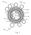
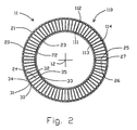
- a rotary module 10 is shown in Figs. 1, 2, 3 and 4.
- the module includes a rotor 11 revolving about axis 12 in the direction shown by arrow 13 within stator 14.
- the apparatus of the invention may be configured for flow through the adsorber elements in the radial, axial or oblique conical directions relative to the rotor axis.
- radial flow has the advantage that the centripetal acceleration will lie parallel to the flow path for most favourable stabilization ofbuoyancy-driven free convection, as well as centrifugal clamping of granular adsorbent with uniform flow distribution.
- the rotor 11 is of annular section, having concentrically to axis 12 an outer cylindrical wall 20 whose external surface is first valve surface 21, and an inner cylindrical wall 22 whose internal surface is second valve surface 23.
- the rotor has (in the plane of the section defined by arrows 15 and 16 in Fig. 4) a total of "N" radial flow adsorber elements 24.
- An adjacent pair of adsorber elements 25 and 26 are separated by partition 27 which is structurally and sealingly joined to outer wall 20 and inner wall 22.
- Adjacent adsorber elements 25 and 26 are angularly spaced relative to axis 12 by an angle of [360° / N].
- Adsorber element 24 has a first end 30 defined by support screen 31 and a second end 32 defined by support screen 33.
- the adsorber may be provided as granular adsorbent, whose packing voidage defines a flow path contacting the adsorbent between the first and second ends of the adsorber.
- First aperture or orifice 34 provides flow communication from first valve surface 21 through wall 20 to the first end 30 of adsorber 24.
- Second aperture or orifice 35 provides flow communication from second valve surface 23 through wall 22 to the second end 31 of adsorber 24.
- Support screens 31 and 33 respectively provide flow distribution 32 between first aperture 34 and first end 30, and between second aperture 35 and second end 32, of adsorber element 24.
- Support screen 31 also supports the centrifugal force loading of the adsorbent.
- stator 14 is a pressure housing including an outer cylindrical shell or first valve stator 40 outside the annular rotor 11, and an inner cylindrical shell or second valve stator 41 inside the annular rotor 11.
- Outer shell 40 carries axially extending strip seals (e.g. 42 and 43) sealingly engaged with first valve surface 21, while inner shell 41 carries axially extending strip seals (e.g. 44 and 45) sealingly engaged with second valve surface 23.
- the azimuthal sealing width of the strip seals is greater than the diameters or azimuthal widths of the first and second apertures 34 and 35 opening through the first and second valve surfaces.
- a set of first compartments in the outer shell each open in an angular sector to the first valve surface, and each provide fluid communication between its angular sector of the first valve surface and a manifold external to the module.
- the angular sectors of the compartments are much wider than the angular separation of the adsorber elements.
- the first compartments are separated on the first sealing surface by the strip seals (e.g. 42). Proceeding clockwise in Fig. 3, in the direction of rotor rotation, a first feed pressurization compartment 46 communicates by conduit 47 to first feed pressurization manifold 48, which is maintained at a first intermediate feed pressure. Similarly, a second feed pressurization compartment 50 communicates to second feed pressurization manifold 51, which is maintained at a second intermediate feed pressure higher than the first intermediate feed pressure but less than the higher working pressure.
- module 10 is shown with provision for sequential admission of two feed mixtures, the first feed gas having a lower concentration of the more readily adsorbed component relative to the second feed gas.
- First feed compartment 52 communicates to first feed manifold 53, which is maintained at substantially the higher working pressure.
- second feed compartment 54 communicates to second feed manifold 55, which is maintained at substantially the higher working pressure.
- a first countercurrent blowdown compartment 56 communicates to first countercurrent blowdown manifold 57, which is maintained at a first countercurrent blowdown intermediate pressure.
- a second countercurrent blowdown compartment 58 communicates to second countercurrent blowdown manifold 59, which is maintained at a second countercurrent blowdown intermediate pressure above the lower working pressure.
- a heavy product compartment 60 communicates to heavy product exhaust manifold 61 which is maintained at substantially the lower working pressure. It will be noted that compartment 58 is bounded by strip seals 42 and 43, and similarly all the compartments are bounded and mutually isolated by strip seals.
- a set of second compartments in the inner shell each open in an angular sector to the second valve surface, and each provide fluid communication between its angular sector of the second valve surface and a manifold external to the module.
- the second compartments are separated on the second sealing surface by the strip seals (e.g. 44).
- light product compartment 70 communicates to light product manifold 71, and receives light product gas at substantially the higher working pressure, less frictional pressure drops through the adsorbers and the first and second orifices.
- the light product may be obtained only from adsorbers simultaneously receiving the first feed gas from compartment 52, or from adsorbers receiving both the first and second feed gases.
- a first light reflux exit compartment 72 communicates to first light reflux exit manifold 73, which is maintained at a first light reflux exit pressure, here substantially the higher working pressure less frictional pressure drops.
- a first cocurrent blowdown compartment 74 (which is actually the second light reflux exit compartment), communicates to second light reflux exit manifold 75, which is maintained at a first cocurrent blowdown pressure less than the higher working pressure.
- a second cocurrent blowdown compartment or third light reflux exit compartment 76 communicates to third light reflux exit manifold 77, which is maintained at a second cocurrent blowdown pressure less than the first cocurrent blowdown pressure.
- a third cocurrent blowdown compartment or fourth light reflux exit compartment 78 communicates to fourth light reflux exit manifold 79, which is maintained at a third cocurrent blowdown pressure less than the second cocurrent blowdown pressure.
- a purge compartment 80 communicates to a fourth light reflux return manifold 81, which supplies the fourth light reflux gas which has been expanded from the third cocurrent blowdown pressure to substantially the lower working pressure with an allowance for frictional pressure drops.
- the ordering of light reflux pressurization steps is inverted from the ordering or light reflux exit or cocurrent blowdown steps, so as to maintain a desirable "last out - first in" stratification of light reflux gas packets.
- a first light reflux pressurization compartment 82 communicates to a third light reflux return manifold 83, which supplies the third light reflux gas which has been expanded from the second cocurrent blowdown pressure to a first light reflux pressurization pressure greater than the lower working pressure.
- a second light reflux pressurization compartment 84 communicates to a second light reflux return manifold 85, which supplies the second light reflux gas which has been expanded from the first cocurrent blowdown pressure to a second light reflux pressurization pressure greater than the first light reflux pressurization pressure.
- a third light reflux pressurization compartment 86 communicates to a first light reflux return manifold 87, which supplies the first light reflux gas which has been expanded from approximately the higher pressure to a third light reflux pressurization pressure greater than the second light reflux pressurization pressure, and in this example less than the first feed pressurization pressure.
- Conduits 88 connect first compartment 60 to manifold 61, with multiple conduits providing for good axial flow distribution in compartment 60.
- conduits 89 connect second compartment 80 to manifold 81.
- Stator 14 has base 90 with bearings 91 and 92.
- the annular rotor 11 is supported on end disc 93, whose shaft 94 is supported by bearings 91 and 92.
- Motor 95 is coupled to shaft 94 to drive rotor 11.
- the rotor could alternatively rotate as an annular drum, supported by rollers at several angular positions about its rim and also driven at its rim so that no shaft would be required.
- a rim drive could be provided by a ring gear attached to the rotor, or by a linear electromagnetic motor whose stator would engage an arc of the rim.
- Outer circumferential seals 96 seal the ends of outer strip seals 42 and the edges of first valve surface 21, while inner circumferential seals 97 seal the ends of inner strip seals 44 and the edges of second valve surface 23.
- Rotor 11 has access plug 98 between outer wall 20 and inner wall 22, which provides access for installation and removal of the adsorbent in adsorbers 24.
- Fig. 5 shows a typical PSA cycle which would be obtained using the gas separation system according to the invention
- Fig. 6 shows a similar PSA cycle with heavy reflux recompression of a portion of the first product gas to provide a second feed gas to the process.
- the vertical axis 150 indicates the working pressure in the adsorbers and the pressures in the first and second compartments. Pressure drops due to flow within the adsorber elements are neglected. The higher and lower working pressures are respectively indicated by dotted lines 151 and 152.
- the horizontal axis 155 of Figs. 5 and 6 indicates time, with the PSA cycle period defined by the time interval between points 156 and 157.
- the working pressure in a particular adsorber is pressure 158.
- the cycle for a particular adsorber begins as the first aperture 34 of that adsorber is opened to the first feed pressurization compartment 46, which is fed by first feed supply means 160 at the first intermediate feed pressure 161.
- the pressure in that adsorber rises from pressure 158 at time 157 to the first intermediate feed pressure 161.
- first aperture passes over a seal strip, first closing adsorber 24 to compartment 46 and then opening it to second feed pressurization compartment 50 which is feed by second feed supply means 162 at the second intermediate feed pressure 163.
- the adsorber pressure rises to the second intermediate feed pressure.
- First aperture 34 of adsorber 24 is opened next to first feed compartment 52, which is maintained at substantially the higher pressure by a third feed supply means 165. Once the adsorber pressure has risen to substantially the higher working pressure, its second aperture 35 (which has been closed to all second compartments since time 156) opens to light product compartment 70 and delivers light product 166.
- first aperture 34 of adsorber 24 is opened next to second feed compartment 54, also maintained at substantially the higher pressure by a fourth feed supply means 167.
- the fourth feed supply means supplies a second feed gas, typically richer in the more readily adsorbed component than the first feed gas provided by the first, second and third feed supply means.
- the fourth feed supply means 167 is a "heavy reflux" compressor, recompressing a portion of the heavy product back into the apparatus.
- compartment 54 could be eliminated or consolidated with compartment 52 extended over a wider angular arc of the stator.
- the first aperture 34 of adsorber 24 is then closed to all first compartments, while the second aperture 35 is opened successively to (a) second light reflux exit compartment 74, dropping the adsorber pressure to the first cocurrent blowdown pressure 171 while delivering light reflux gas to second light reflux pressure letdown means 172, (b) third light reflux exit compartment 76, dropping the adsorber pressure to the second cocurrent blowdown pressure 173 while delivering light reflux gas to third light reflux pressure letdown means 174, and (c) fourth light reflux exit compartment 78, dropping the adsorber pressure to the third cocurrent blowdown pressure 175 while delivering light reflux gas to fourth light reflux pressure letdown means 176. Second aperture 35 is then closed for an interval, until the light reflux return steps following the countercurrent blowdown steps.
- the light reflux pressure let-down means may be mechanical expanders or expansion stages for expansion energy recovery, or may be restrictor orifices or throttle valves for irreversible pressure let-down.
- first aperture 34 is opened to first countercurrent blowdown compartment 56, dropping the adsorber pressure to the first countercurrent blowdown intermediate pressure 180 while releasing "heavy" gas (enriched in the more strongly adsorbed component) to first exhaust means 181. Then, first aperture 34 is opened to second countercurrent blowdown compartment 58, dropping the adsorber pressure to the first countercurrent blowdown intermediate pressure 182 while releasing heavy gas to second exhaust means 183. Finally reaching the lower working pressure, first aperture 34 is opened to heavy product compartment 60, dropping the adsorber pressure to the lower pressure 152 while releasing heavy gas to third exhaust means 184.
- the second aperture 35 opens to purge compartment 80, which receives fourth light reflux gas from fourth light reflux pressure let-down means 176 in order to displace more heavy gas into first product compartment 60.
- the heavy gas from the first, second and third exhaust means is delivered as the heavy product 185.
- this gas is partly released as the heavy product 185, while the balance is redirected as "heavy reflux” 187 to the heavy reflux compressor as fourth feed supply means 167.
- light reflux enables an approach to high purity of the less readily adsorbed ("light") component in the light product
- heavy reflux enables an approach to high purity of the more readily adsorbed (“heavy") component in the heavy product.
- the adsorber is then repressurized by light reflux gas after the first and second apertures close to compartments 60 and 80.
- the second aperture 35 is opened to first light reflux pressurization compartment 82 to raise the adsorber pressure to the first light reflux pressurization pressure 190 while receiving third light reflux gas from the third light reflux pressure letdown means 174
- the second aperture 35 is opened to second light reflux pressurization compartment 84 to raise the adsorber pressure to the second light reflux pressurization pressure 191 while receiving second light reflux gas from the second light reflux pressure letdown means 172
- the second aperture 35 is opened to third light reflux pressurization compartment 86 to raise the adsorber pressure to the third light reflux pressurization pressure 192 while receiving first light reflux gas from the first light reflux pressure letdown means 170.
- the pressure variation waveform in each adsorber would be a rectangular staircase if there were no throttling in the first and second valves.
- all of the apertures are closely identical to each other.
- the rate of pressure change in each pressurization or blowdown step will be restricted by throttling in ports (or in clearance or labyrinth sealing gaps) of the first and second valve means, or by throttling in the apertures at first and second ends of the adsorbers, resulting in the typical pressure waveform depicted in Figs. 5 and 6.
- the apertures may be opened slowly by the seal strips, to provide flow restriction throttling between the apertures and the seal strips, which may have a serrated edge (e.g. with notches or tapered slits in the edge of the seal strip) so that the apertures are only opened to full flow gradually.
- the cycle could be generalized by having more or fewer intermediate stages in each major step of feed pressurization, countercurrent blowdown exhaust, or light reflux.
- a stage of feed pressurization (typically the first stage) could be performed by equalization with atmosphere as an intermediate pressure of the cycle.
- a stage of countercurrent blowdown could be performed by equalization with atmosphere as an intermediate pressure of the cycle.
- Fig. 7 is a simplified schematic of a PSA system, in accordance with the present invention, for separating oxygen from air, using nitrogen-selective zeolite adsorbents.
- the light product is concentrated oxygen, while the heavy product is nitrogen-enriched air usually vented as waste.
- the cycle lower pressure 152 is nominally atmospheric pressure.
- Feed air is introduced through filter intake 200 to a feed compressor 201.
- the feed compressor includes compressor first stage 202, intercooler 203, compressor second stage 204, second intercooler 205, compressor third stage 206, third intercooler 207, and compressor fourth stage 208.
- the feed compressor 201 as described may be a four stage axial compressor or centrifugal compressor with motor 209 as prime mover coupled by shaft 210, and the intercoolers are optional.
- the feed compressor first and second stages are the first feed supply means 160, delivering feed gas at the first intermediate feed pressure 161 via conduit 212 and water condensate separator 213 to first feed pressurization manifold 48.
- Feed compressor third stage 206 is the second feed supply means 162, delivering feed gas at the second intermediate feed pressure 163 via conduit 214 and water condensate separator 215 to second feed pressurization manifold 51.
- Feed compressor fourth stage 208 is the third feed supply means 165, delivering feed gas at the higher pressure 151 via conduit 216 and water condensate separator 217 to feed manifold 53.
- Light product oxygen flow is delivered from light product manifold 71 by conduit 218, maintained at substantially the higher pressure less frictional pressure drops.
- the apparatus of Fig. 7 includes energy recovery expanders, including light reflux expander 220 (here including four stages) and countercurrent blowdown expander 221 (here including two stages), coupled to feed compressor 201 by shaft 222.
- the expander stages may be provided for example as radial inflow turbine stages, as full admission axial turbine stages with separate wheels, or as partial admission impulse turbine stages combined in a single wheel.
- first light reflux exit manifold 73 flows at the higher pressure via conduit 224 and heater 225 to first light pressure letdown means 170 which here is first light reflux expander stage 226, and then flows at the third light reflux pressurization pressure 192 by conduit 227 to the first light reflux return manifold 87.
- Light reflux gas from second light reflux exit manifold 75 flows at the first cocurrent blowdown pressure 171 via conduit 228 and heater 225 to second light reflux pressure letdown means 172, here the second expander stage 230, and then flows at the second light reflux pressurization pressure 191 by conduit 231 to the second light reflux return manifold 85.
- Light reflux gas from third light reflux exit manifold 77 flows at the second cocurrent blowdown pressure 173 via conduit 232 and heater 225 to third light reflux pressure letdown means 174, here the third expander stage 234, and then flows at the first light reflux pressurization pressure 190 by conduit 235 to the third light reflux return manifold 83.
- light reflux gas from fourth light reflux exit manifold 79 flows at the third cocurrent blowdown pressure 175 via conduit 236 and heater 225 to fourth light reflux pressure letdown means 176, here the fourth light reflux expander stage 238, and then flows at substantially the lower pressure 152 by conduit 239 to the fourth light reflux return manifold 81.
- Heavy countercurrent blowdown gas from first countercurrent blowdown manifold 57 flows at first countercurrent blowdown intermediate pressure 180 by conduit 240 to heater 241 and thence to first stage 242 of the countercurrent blowdown expander 221 as first exhaust means 181, and is discharged from the expander to exhaust manifold 243 at substantially the lower pressure 152.
- Countercurrent blowdown gas from second countercurrent blowdown manifold 59 flows at second countercurrent blowdown intermediate pressure 182 by conduit 244 to heater 241 and thence to second stage 245 of the countercurrent blowdown expander 221 as second exhaust means 183, and is discharged from the expander to exhaust manifold 243 at substantially the lower pressure 152.
- heavy gas from heavy product exhaust manifold 61 flows by conduit 246 as third exhaust means 184 to exhaust manifold 243 delivering the heavy product gas 185 to be vented at substantially the lower pressure 152.
- Heaters 225 and 241 raise the temperatures ofgases entering expanders 220 and 221, thus augmenting the recovery of expansion energy and increasing the power transmitted by shaft 222 from expanders 220 and 221 to feed compressor 201, and reducing the power required from prime mover 209. While heaters 225 and 241 are means to provide heat to the expanders, intercoolers 203, 205 and 207 are means to remove heat from the feed compressor and serve to reduce the required power of the higher compressor stages. The intercoolers 203, 205, 207 are optional features of the invention.
- the temperature of the second ends 35 of the adsorbers 24 may be higher than the temperature of their first ends 34.
- the adsorbers have a thermal gradient along the flow path, with higher temperature at their second end relative to the first end.
- Adsorber rotor 11 then acts as a thermal rotary regenerator, as in regenerative gas turbine engines having a compressor 201 and an expander 220.
- Heat provided to the PSA process by heater 225 assists powering the process according to a regenerative thermodynamic power cycle, similar to advanced regenerative gas turbine engines approximately realizing the Ericsson thermodynamic cycle with intercooling on the compression side and interstage heating on the expansion side.
- the total light reflux flow is much less than the feed flow because ofthe strong bulk adsorption of nitrogen. Accordingly the power recoverable from the expanders is much less than the power required by the compressor, but will still contribute significantly to enhanced efficiency of oxygen production.
- the light reflux expander stages and the countercurrent blowdown expander stages may be replaced by restrictor orifices or throttle valves for pressure letdown.
- the schematic of Fig. 7 shows a single shaft supporting the compressor stages, the countercurrent blowdown or exhaust expander stages, and the light reflux stages, as well as coupling the compressor to the prime mover.
- separate shafts and even separate prime movers may be used for the distinct compression and expansion stages within the scope of the present invention.
- Fig. 8 shows a radial flow rotary PSA module 300 in which the first and second valve surface 21, 23 are respectively provided as hard-faced ported surfaces on the first and second valve stators 40 and 41.
- Sliding seals 380 are provided on rotor 11 between each adsorber 24 and its neighbours, to engage both valve surfaces 21, 23 in fluid sealing contact.
- Seals 380 may have a wear surface of a suitable composite material based on PTFE or carbon, and should be compliantly mounted on rotor 11 so as to compensate for wear, deflections and misalignment.
- Ports 381 may be sized, particularly at the leading edge of each compartment, to provide controlled throttling for smooth pressure equalization between adsorbers and that compartment, as each adsorber in turn is opened to that compartment.
- Split stream vacuum pump 260 receives the countercurrent blowdown and exhaust flow in three streams receiving exhaust gas at incrementally reduced pressures from countercurrent blowdown compartment 56, compartment 58 and compartment 60.
- the combined exhaust gas is discharged as heavy product gas.
- initial feed pressurization is performed from atmosphere, so a first feed pressurization conduit 382 admits feed air directly from inlet filter 200 to first feed pressurization compartment 46 at substantially atmospheric pressure.
- the first discharge port of feed compressor 201 now communicates to second feed pressurization compartment 50.
- the compressor is shown as a split stage machine with inlet 391, and three discharges 392, 393 and 394 at incrementally higher pressures.
- a split stream light reflux expander 220 is provided to provide pressure let-down of four light reflux stages with energy recovery.
- the light reflux expander 220 provides pressure let-down for each of four light reflux stages.
- the stages may optionally be compartmentalized within the light reflux expander 220 to minimize mixing of gas concentration between the stages.
- the light product purity will tend to decline from the light reflux stages of higher pressure to those of lower pressure, so that a desirable stratification of the light reflux can be maintained if mixing is avoided.
- Light reflux expander 220 is coupled to drive light product pressure booster compressor 396.
- Compressor 396 receives the light product from compartment 70, and delivers light product (compressed to a delivery pressure above the higher pressure of the PSA cycle) from delivery conduit 218. Since the light reflux and light product are both enriched oxygen streams of approximately the same purity, expander 220 and light product compressor 396 may be hermetically enclosed in a single housing similar to a turbocharger.
- Fig. 9 is an axial sectional view of an axial flow rotary PSA module 600 for small scale oxygen production. The view is taken through compartments 54 and 70 at the higher pressure, and compartments 60 and 80 at the lower pressure. The flow path in adsorbers 24 is now parallel to axis 601. A better understanding will be obtained from Figs. 10 and 11, which are cross sections of module 600 in the planes respectively defined by arrows 602-603 and 604-605.
- the adsorber rotor 11 contains the "N" adsorbers 24 in adsorber wheel 608, and revolves between the first valve stator 40 and the second valve stator 41. Compressed feed air is supplied to compartment 54 as indicated by arrow 501, while nitrogen enriched exhaust gas is exhausted from compartment 60 as indicated by arrow 502.
- circumferential seals 608 and 609 bound first sealing face 21, and circumferential seals 610 and 611 bound second sealing face 23.
- the sealing faces are flat discs.
- the circumferential seals also define the ends of seals between the adsorbers, or alternatively of dynamic seals in the sealing faces between the stator compartments.
- Rotor 11 has a stub shaft 511 supported by bearing 512 in first bearing housing 513, which is integral with first valve stator 40.
- Second valve stator 41 has a stub shaft engaging the rotor 11 with guide bushing 612.
- a flanged cover plate 615 is provided for structural connection and fluid sealing enclosure between the first valve stator 40 and the second valve stator 41.
- Rotor 11 includes seal carrier 618 attached at joint 619 to adsorber wheel 608, and extending between the back of second valve stator 41 and cover plate 615 to sealing face 621 which is contacted by dynamic seal 625.
- Seal 625 prevents contamination of the light product gas by leakage from chamber 626 adjacent the first valve sealing face 21 to chamber 627 adjacent the second valve sealing face 23.
- Seal 625 needs to be tight against leakage that could compromise product purity. By manufacturing this seal to a smaller diameter than the valve faces outer diameter, frictional torque from this seal is greatly reduced than if this seal were at the full rotor diameter. The circumferential perimeter exposed to leakage is also reduced. As in Fig. 8, a split stream light reflux expander 220 with close-coupled light product compressor 396, may be installed inside the light valve stator.
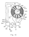
- Fig. 10 shows the first valve face 21 of the axial flow rotary PSA module 600 shown in Fig. 9, at section 602 - 603, with fluid connections to a split stream feed compressor 201 and a split stream countercurrent blowdown expander 221.
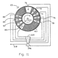
- Fig. 11 shows the second valve face 23 of the axial flow rotary PSA module 600 shown in Fig. 9, at section 604 - 605, with fluid connections to a split stream light reflux expander 220 and light product booster compressor 396.
- Arrow 670 indicates the direction of rotation by adsorber rotor 11.
- the open area of valve face 21 ported to the feed and exhaust compartments is indicated by clear angular segments 46, 50, 52, 56, 58, 60 corresponding to those compartments, between circumferential seals 608 and 609.
- the closed area of valve face 21 between compartments is indicated by cross-hatched sectors 675 and 676.
- the open area of valve face 23 ported to the light reflux exit and return compartments is indicated by clear angular segments 70, 72, 74, 76, 78, 80, 82, 84, 86 corresponding to those compartments, while the closed are of valve face 23 between the light reflux and return compartments is indicated by the cross-hatched sectors.
- Typical closed sector 675 shown in Fig. 10, provides a transition for an adsorber, between being open to compartment 56 and open to compartment 58. Gradual opening is provided at the leading edges 677 and 678 of compartments, so as to achieve gentle pressure equalization of an adsorber being opened to a new compartment.
- Much wider closed sectors e.g. 676 are provided to substantially close flow to or from one end of the adsorbers when pressurization or blowdown is being performed from the other end.
- Sealing between compartments at typical closed sectors may be provided by rubbing seals on either stator or rotor against a ported hard-faced sealing counter face on the opposing rotor or stator, or by narrow gap clearance seals on the stator with the area of the narrow sealing gap defined by the cross hatched area of the nominally closed surface.
- Rubbing seals may be provided as radial strip seals, with a self-lubricating solid material such as suitable PTFE compounds or graphite, or as brush seals in which a tightly packed brush of compliant fibers rubs against the counter face.
- cross-hatched sectors 675 and 676 would be non-ported portions of the hard-faced sealing counter face on the stator. If the rubbing seals are on the stator, the ported hard-faced counter face is on the rotor valve face. Those rubbing seals could be provided as full sector strips for narrow closed sectors (e.g. 675). For the wider closed sectors (e.g. 676), narrow radial rubbing seals may be used as the edges 678 and 679, and at intervals between those edges, to reduce friction in comparison with rubbing engagement across the full area of such wide sectors.
- the leakage discharge coefficient to or from the clearance gap varies according to the angular position of the adsorber, thus providing gentle pressure equalization as desired.
- the clearance gap geometry is optimized in typical nominally closed sectors (e.g. 675) so that the leakage in the clearance gap is mostly used for adsorber pressure equalization, thus minimizing through leakage between compartments.
- the clearance gap is tapered in such sectors 675 to widen the gap toward compartments being opened, so that the rate of pressure change in pressure equalization is close to linear and rubbing friction is reduced.
- the clearance gap would be relatively narrow to minimize flows at that end of adsorbers passing through those sectors.
- valve face seals For all types of valve face seals described above, it is preferable that consistent performance be achieved over time, and that all "N" adsorbers experience the same flow pattern after all perturbations from seal imperfections. This consideration favours placing rubbing seals on the stator so that any imperfections are experienced similarly by all adsorbers. If the seals are mounted on the rotor between adsorbers, it is preferable that they are closely identical and highly reliable to avoid upsetting leakages between adjacent adsorbers.
- the sealing system should have a suitable self-aligning suspension.
- rubbing seal or clearance seal elements may be supported on elastomeric supports, bellows or diaphragms to provide the self-aligning suspension with static sealing behind the dynamic seal elements. Rubbing seals may be energized into sealing contact by a combination of elastic preload and gas pressure loading.
- gap control for blowdown compartments is achieved through a self-regulating seal in which the correct gap is maintained by a balance between gas pressure in the gap of a clearance seal segment, and the pressures of adjacent blowdown compartments loading the seal behind that segment.
- gap control is achieved through a self-regulating seal in which the correct gap is maintained by a balance between gas pressure in the gap of a clearance seal segment, and an intermediate pressure loading the seal behind that segment, with the intermediate pressure being the average of the pressure of the flow paths approaching the clearance seal segment and the pressure of flow paths leaving the clearance seal segment.
- Fig. 12a shows a self-regulating clearance seal 700 for use with the countercurrent blowdown compartments 56, 58, 60 and the cocurrent blowdown compartments 72, 74, 76, 78 of an axial-flow-configured rotary PSA module, such as the PSA module 600 shown in Fig. 9.
- the self-regulating clearance seal 700 comprises a sealing element 702, and a resilient biasing element 704 coupled to the sealing element 702.
- the sealing element 702 is interposed between the first valve face 21 of the rotor 11 and the corresponding stator valve face of the stator 14, when used in conjunction with countercurrent blowdown compartments 56, 58, 60, or is interposed between the second valve face 23 of the rotor 11 and the corresponding stator valve face of the stator 14, when used in conjunction with the cocurrent blowdown compartments 72, 74, 76, 78 .
- Sealing elements 702 are positioned along the circumference of the stator valve face, with each sealing element 702 being positioned between a pair of adjacent blowdown compartment, such as between the blowdown compartments 56,58 shown in Fig.12a. However, it should be understood that the sealing element 702 may be positioned between any blowdown compartments, or proximate to any first gas flow conduit which facilitates pressure blowdown of a second gas flow conduit moving past the first gas flow conduit.
- Each sealing element 702 comprises an elongate slipper having first and second opposite ends 706a, 706b, a substantially planar sealing face 708 extending between the opposite ends 706, and an opposing second face 710 also extending between the opposite ends 706 but positioned opposite the sealing face 708.
- the sealing element 702 is positioned between the rotor valve face 21 (or the rotor valve face 23) and the corresponding stator valve face, with the first end 706a being positioned adjacent one of the blowdown compartments, such as the blowdown compartment 56, and with the second end 706b being proximate to the adjacent blowdown compartment, such as the blowdown compartment 58.
- the first end 706a of the sealing element 702 is pivotally coupled to the rotor valve face 21 (or rotor valve face 23) through a bearing 712 positioned adj acent one side edge of the sealing element 702, and which extends laterally outwards from the sealing element 702 and engages a corresponding race on the rotor 11.
- a similar bearing 712 (not shown) is positioned on the opposite side edge of the sealing element 702 and engages a corresponding race on the rotor 11.
- a variable clearance gap 714 is maintained between the sealing face 708 and the rotor valve face 21 (or rotor valve face 23) so as to allow the gas flow rate through the apertures 34 (or the apertures 35) of the rotor 11 to vary as the height of the clearance gap 714 between the sealing face 708 and the rotor valve face is varied.
- the clearance gap 714 at the first end 706a is maintained substantially constant, and is sized to minimize gas flows between adjacent blowdown compartments, such as between the blowdown compartment 56 and the blowdown compartment 58.
- the clearance gap 714 at the first end 706a of the sealing element 702 is substantially independent of the degree of roundness of the rotor valve face.
- friction between the sealing face 708 and the rotor valve face 21, 23 is less than if the first end 706a actually contacted the rotor valve face 21, 23.
- the bearings 712 are not essential features of the invention.
- the sealing element 702 includes a pair ofprotuberances integrally formed with the sealing element 702 and which extend laterally outwards from the side edges of the sealing element 702 for engagement with the bearing races on the rotor 11.
- the bearings 712 are replaced with a single rod which extends through the sealing element 702 between the side edges for engagement with the bearing races on the rotor 11. Further, in applications where precise control over the clearance gap 714 at the first end 706a is not critical, or where the rotor valve face is precision machined, the first end 706a may be coupled to the stator 14.
- the biasing element 704 comprises a resilient element including a first side wall 716a, and a second side wall 716b opposite the first side wall 716a.
- the biasing element 704 is positioned equidistantly between the first and second ends 706a, 706b and extends between the opposing face 710 and the stator valve face between adjacent blowdown compartments.
- the biasing element 704 prevents the sealing element 702 from rotating with the rotor 11 as the apertures 34 (or the apertures 35) of the rotor 11 move past the sealing face 708, and urges the sealing face 708 towards the rotor valve face.
- the first side wall 716a of the resilient biasing element 704 is concave so to allow the height of the clearance gap 714 to be varied.
- the biasing element 704 does not press the sealing face 708 against the rotor valve face.
- the biasing element 704 is sized so the sealing face 708 tapers away from the rotor valve face from the first end 706a towards the second end 706b, so that the clearance gap 714 is greater adjacent the second end 706b than adjacent the first end 706a.
- a first compartment 718a is provided between the first side wall 716a of each biasing element 704, the portion of the stator valve face extending between the first side wall 716a and the blowdown compartment immediately adjacent thereto (blowdown compartment 56), and the portion of the opposing face 710 extending between the first side wall 716a and the first end 706a.
- a second compartment 718b is provided between the second side wall 716b of each biasing element 704, the portion of the stator valve face extending between the second side wall 716b and the blowdown compartment immediately adjacent thereto (blowdown compartment 58), and the portion of the opposing face 710 extending between the second side wall 716b and the second end 706b.
- the second compartment 718b communicates with a first compartment 718a associated with the adjacent sealing element.
- the rotor rotates in the direction of the arrow denoted by reference numeral 720. Since clearance seals 700 are positioned along the circumference of the stator valve face between adjacent blowdown compartments, the first end 706a of each sealing element 702 will be maintained at the pressure level of one of the blowdown compartments, and the second end 706b of each sealing element 702 will be maintained at the pressure level of the adjacent blowdown compartment. In the example shown in Fig. 12a, the first end 706a is maintained at the pressure level of the blowdown compartment 56, and the second end 706b is maintained at the pressure level of the blowdown compartment 58.
- the pressure transition profile between the first blowdown compartment (blowdown compartment 56) and the second blowdown compartment (blowdown compartment 58) is substantially linear so as to maintain equilibrium between the adsorbent material and the mass transfer front of the gas.
- the rate of gas flow depends on the height of the clearance gap 714.
- the pressure transition profile would normally have the concave shape (denoted by reference numeral 722) shown in Fig. 12b, whereas if the clearance gap 714 increased too slowly, the pressure transition profile would normally have the convex shape (denoted by reference numeral 724).
- the height of the clearance gap 714 automatically adjusts to obtain the linear pressure transition profile (denoted by reference numeral 726).
- each biasing element 704 is positioned equidistantly between the first and second ends 706a, 706b, the first and second compartments 718 are of equal size. Therefore, as the clearance seals 700 are positioned along the circumference of the stator valve face between adjacent blowdown compartments, the pressure acting against the opposing face 710 at the position occupied by the biasing element 704 is equal to the average of the pressure of the blowdown compartment 56 and the blowdown compartment 58 (as shown by the reference numeral 728).
- the pressure (as shown by reference numeral 730) at the sealing face 708 at the same position will be less than the average pressure 728, causing a moment to be developed about the first end 706a tending to force the clearance gap 714 to narrow.
- the narrowing of the clearance gap 714 will cause a flattening of the pressure transition profile.
- the clearance gap 714 (and the angle between the sealing face 708 and the rotor face) will continue to narrow in response to the pressure differential between the compartments 716 and the apertures 34, 35 until the pressure 728 equals the pressure 728, at which point a linear pressure transition profile will be obtained.
- the pressure (as shown by reference numeral 732) at the sealing face 708 at the position of the biasing element 704 will be greater than the average pressure 728, causing an opposite moment to be developed about the first end 706a tending to force the clearance gap 714 to widen.
- the widening of the clearance gap 714 again will cause a flattening of the pressure transition profile.
- the clearance gap 714 (and the angle between the sealing face 708 and the rotor face) will continue to widen in response to the pressure differential between the compartments 718 and the apertures 34, 35 until the pressure 732 equals the pressure 728, at which point a linear pressure transition profile again will be obtained.
- the sealing face 708 includes a plurality of passages, provided as a labyrinth, for increasing the flow resistance for a given channel gap 714 height.
- the sealing face 708 includes a plurality of planar stepped portions, so that the sealing face 708 tapers away from the rotor face over a plurality of steps and the flow resistance is increased for a given angle of deflection of the sealing element 702.
- the biasing element 704 is positioned at an off-centre position so as to provide a controlled non-linear pressure transition profile.
- the clearance seals 700 are used to provide sealing for closed sectors, such as the closed axial flow sectors 676,676 shown in Fig. 10.
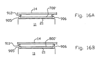
- the bearings 712 are replaced with fasteners which rigidly secure the first end 706a of the sealing element 702 to a race on the rotor valve face 21 (or rotor valve face 23) so as to prevent variations in the height of the clearance gap 714.
- the first and second compartments 718a, 718b do not communicate with any blowdown compartments, but are pressurized to the pressure of the apertures 34, 35.
- the sealing faces 708 are urged towards the rotor face so as to limit the gas flow through the apertures 34, 35.
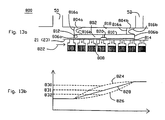
- Fig. 13a shows a self-regulating clearance seal 800 for use with the pressurization compartments 46, 50, 52, 54 or the light reflux return compartments 82, 84, 86 of an axial-flow configured rotary PSA module, such as the PSA module 600 shown in Fig. 9.
- the clearance seal 800 may even be used in connection with heavy reflux return compartments if desired.
- the self-regulating seal 800 is substantially similar to the self-regulating seal 700, comprising a sealing element 802, and first and second resilient biasing elements 804a, 804b coupled to the sealing element 802.
- the sealing element 802 is interposed between the first valve face 21 of the rotor 11 and the corresponding stator valve face of the stator 14, when used in conjunction with pressurization compartments 46, 50, 52, 54, or is interposed between the second valve face 23 of the rotor 11 and the corresponding stator valve face of the stator 14, when used in conjunction with the light reflux return compartments 82, 84, 86.
- Sealing elements 802 are positioned along the circumference of the stator valve face, with each sealing element 802 being positioned between a pair of adjacent pressurization or reflux return compartment, such as between the pressurization compartments 50, 52 shown in Fig. 12a.
- the sealing elements 702 may be positioned between any pressurization compartments, or proximate to any first gas flow conduit which facilitates pressurization of a second gas flow conduit moving past the first gas flow conduit.
- the clearance seals 800 may be used without any pressurization compartments, to provide sealing for closed sectors.
- Each sealing element 802 comprises an elongate slipper having first and second opposite ends 806a, 806b, a substantially planar sealing face 808 extending between the opposite ends 806, and an opposing second face 810 also extending between the opposite ends 806 but positioned opposite the sealing face 808.
- the sealing element 802 is positioned between the rotor valve face 21 (or the rotor valve face 23) and the corresponding stator valve face, with the first end 806a being positioned adjacent one of the pressurization/ reflux return compartments, such as the pressurization compartment 50, and with the second end 806b being proximate to the adjacent pressurization/reflux return compartment, such as the pressurization compartment 52.
- the first end 806a of the sealing element 802 is pivotally coupled to the rotor valve face 21 (or rotor valve face 23) through bearings 812, as with the self-regulating seal 700.
- Each biasing element 804 comprises a resilient element including a first side wall 816a, and a second side wall 816b opposite the first side wall 816a.
- the biasing elements 804 are positioned at opposite ends of the sealing element 802, with the first biasing element 804a being positioned adjacent the first end 806a, and the second biasing element 804b being positioned adjacent the second end 806b.
- Each pair of biasing elements 804a, 804b extend between the opposing face 810 and the stator valve face between a pair of adjacent pressurization/reflux return compartments.
- the biasing elements 804 prevent the sealing element 802 from rotating with the rotor 11 as the apertures 34 (or the apertures 35) of the rotor 11 move past the sealing face 808, and urge the sealing face 808 towards the rotor valve face. Further, since the gas flow rate through the apertures 34, 35 of the rotor 11 is dependent upon the height of the clearance gap 814, the second side wall 816b of each resilient biasing element 804 is concave so to allow the height of the clearance gap 814 to be varied. However, to reduce friction between the sealing face 808 and the rotor valve face, preferably the biasing elements 804 do not press the sealing face 808 against the rotor valve face.
- the biasing elements 804 are also sized so the sealing face 808 tapers away from the rotor valve face from the first end 806a towards the second end 806b, so that the clearance gap 814 between the sealing face 808 and the rotor face is greater adjacent the second end 806b than adjacent the first end 806a.
- this feature provides a gradual pressure increase for the gas flowing into the flow path ends 30, 32 of the adsorbers 24 as the corresponding apertures 34, 35 of the rotor 11 traverse the sealing face 808.
- a compartment 818 is provided between the second side wall 816b of the first biasing element 804a, the first side wall 816a of the second biasing element 804a, and the portions of the stator valve face and the opposing face 810 extending therebetween.
- the compartment 818 communicates with the pressurization/reflux return compartment adjacent the second end 806b (pressurization compartment 52) through an aperture 820 provided in the sealing element 802.
- the aperture 820 is positioned equidistantly between the first and second ends 806a, 806b and extends between the sealing face 808 and the opposing face 810.
- the rotor rotates in the direction of the arrow denoted by reference numeral 822. Since clearance seals 800 are positioned along the circumference of the stator valve face between adj acent pressurization/reflux return compartments, the first end 806a will be exposed to a pressure from one of the pressurization/reflux return compartments, and the second end 806b will be exposed to a greater pressure from the adjacent pressurization/reflux return compartment. In the example shown in Fig. 13a, the first end 806a is exposed to a pressure from the pressurization compartment 50, and the second end 806b is exposed to a greater pressure from the pressurization compartment 52.
- the gas entering the aperture 34, 35 is equalized to the pressure of the pressurization compartment 50.
- the clearance gap 814 increases, thereby allowing the rate of gas flow into the aperture 34, 35 to increase and the pressure at the corresponding flow path end 30, 32 of the adsorber 24 to increase.
- the pressure transition profile between the first pressurization/reflux return compartment (pressurization compartment 50) and the second pressurization/reflux return compartment (pressurization compartment 52) is substantially linear so as to maintain equilibrium between the adsorbent material and the mass transfer front of the gas.
- the rate of gas flow depends on the height of the clearance gap 814.
- the pressure transition profile would normally have the convex shape (denoted by reference numeral 824) shown in Fig. 13b, whereas if the clearance gap 814 increased too slowly, the pressure transition profile would normally have the concave shape (denoted by reference numeral 826).
- the height of the clearance gap 814 automatically adjusts to obtain the linear pressure transition profile (denoted by reference numeral 828).
- the compartment 818 communicates with the pressurization/reflux return compartment adjacent the second end 806b through a passage 820 positioned equidistantly between the first and second ends 806a, 806b, the compartment 818 of each sealing element 802 will be maintained at a pressure level which is equal to the pressure of the sealing face 808 at the equidistant position. If the clearance gap 814 increases too rapidly, the pressure (as shown by reference numeral 830) in the compartment 818 will be greater than the average(denoted by reference numeral 831) of the pressure of the pressurization compartment 52 and the pressure of the pressurization compartment 54.
- the clearance gap 814 (and the angle between the sealing face 808 and the rotor face) will continue to narrow in response to the pressure differential between the compartment 818 and the apertures 34, 35 until the pressure 830 equals the average of the pressure of the pressurization compartment 52 and the pressurization compartment 54, at which point a linear pressure transition profile will be obtained.
- the pressure (as shown by reference numeral 832) in the compartment 818 will be less than the average of the pressure of the pressurization compartment 52 and the pressurization compartment 54. Since the pressure exerted against the sealing face 808 between the second end 806a and the position of the passage 820 will be significantly greater than the pressure 832, and the pressure exerted against the sealing face 808 between the first end 806a and the position of the passage 820 will only be slightly less than the pressure 832, a moment will be developed about the first end 806a tending to force the clearance gap 814 to widen The widening of the clearance gap 814 will cause a flattening of the pressure transition profile.
- the clearance gap 814 (and the angle between the sealing face 808 and the rotor face) will continue to widen in response to the pressure differential between the compartment 818 and the apertures 34, 35 until the pressure 832 equals the average of the pressure of the pressurization compartment 52 and the pressurization compartment 54, at which point a linear pressure transition profile will be obtained.
- the sealing face 808 includes a plurality of passages, provided as a labyrinth, for increasing the flow resistance for a given channel gap 814 height.
- the sealing face 808 includes a plurality of planar stepped portions, so that the sealing face 808 tapers away from the rotor face over a plurality of steps and the flow resistance is increased for a given angle of deflection of the sealing element 802.
- the aperture 820 is positioned at an off-centre position so as to provide a controlled non-linear pressure transition profile.
- the clearance seals 800 are used to provide sealing for closed sectors, such as the closed axial flow sectors 675, 676 shown in Fig. 10.
- the bearings 812 are replaced with fasteners which rigidly secure the first end 806a of the sealing element 802 to a race on the rotor valve face 21 (or rotor valve face 23) so as to prevent variations in the height ofthe clearance gap 814.
- the first and second compartments 818 do not communicate with any blowdown compartments, but are pressurized to the pressure of the apertures 34, 35.
- the sealing faces 808 are urged towards the rotor face so as to limit the gas flow through the apertures 34, 35.
- Fig. 24 shows self-regulating clearance seals 700', 800' respectively for use with the blowdown and pressurization compartments of a radial-flow configured rotary PSA module.
- the blowdown clearance seals 700' are shown positioned between the stator and rotor valve faces for use with the countercurrent blowdown compartments 56, 58, 60 and the cocurrent blowdown compartments 72, 74, 76, 78.
- the pressurization clearance seals 800' are shown positioned between the stator and rotor valve faces for use with the pressurization compartments 46, 50, 52, and the light reflux return compartments 82, 84, 86.
- Fig. 24 shows self-regulating clearance seals 700', 800' respectively for use with the blowdown and pressurization compartments of a radial-flow configured rotary PSA module.
- the blowdown clearance seals 700' are shown positioned between the stator and rotor valve faces for use with the countercurrent blowdown compartments 56, 58, 60 and the cocurrent blowdown compartments 72
- blowdown clearance seals 700 identical to clearance seals 700', but being used without blowdown compartments for sealing closed radial flow sectors, similar to the closed axial flow sectors 675, 676 shown in Fig. 10.
- pressurization seals 800 identical to clearance seals 700" may be used without pressurization compartments for sealing closed radial flow sectors.
- the clearance seals 700', 800' are respectively substantially identical to the clearance seals 700, 800. Unlike the clearance seals 700, 800, however, the clearance seals 700', 800' respectively have arcuate sealing faces 708', 808' and arcuate opposed faces 710', 810' instead of the substantially planar sealing faces 708, 808 and the substantially planar opposed faces 710, 810 to allow the clearance seals 700', 800' to regulate the flow of radial gas flow through the rotary PSA module.
- the clearance seals 700', 800' are not limited for use with rotary PSA modules.
- the clearance seals 700' may be used to regulate the pressure letdown of radial flow of gas between any first gas flow conduit and any second gas flow conduit moving past the first gas flow conduit.
- the clearance seals 800' may be used to regulate the pressurization, from a first gas flow conduit, of a second gas conduit which moves past the first gas flow conduit.
- Fig. 15 is an unrolled view of the first valve face seals from Fig. 14, with the view split arbitrarily at feed pressurization compartment 46.
- Figs. 16A and 16B are sections 901- 902 and 903 - 904 respectively of Fig. 15.
- Circumferential seals 905 and 906 provide sealing between the stator 14 and rotor 11 at the ends thereof, to bound the first sealing face 21 at each end while closing the function compartments (as well as pressure balancing compartments that have no intended through flow function) between each adjacent pair of clearance seals 700', 700", 800' and 800".
- Seals 905 and 906 are attached to stator 14 in order to maintain the seals in position while reacting frictional torques.
- Seals 905 and 906 may be solid or split rings. In the case of split ring circumferential seals, the split should be at a point of the circumference where the working pressure most closely approaches external ambient pressure, and may be an anchor point for tensile or pin connections to the casing.
- Hinges 712 and 812 of respectively the blowdown and pressurization clearance seals are attached to the circumferential seals which thus hold the clearance seals in place.
- the clearance seals through their hinge connections may also desirably serve as struts to control the relative spacing of the circumferential seals to resist lateral deflections under pressure loading.
- Static seals 911 and 912 are provided with the appropriate curvature to flex in tension for the portions of the circumferential seals respectively sealing compartments at positive working pressure and vacuum (if any).
- Static seals 911 and 912 may be substantially identical in section and material of construction to the biasing elements 704, 804a and 804b of the clearance seals. The section and material should provide adequate compliance to absorb deflections due to manufacturing tolerances, initial misalignment, pressure and thermal loads, and wear of the seal surfaces.
- static seals 911 and 912 and biasing elements 704, 804a and 804b are jointed at the corners of the function compartments (and supplementary pressure balancing compartments 913) to maintain static sealing of those compartments behind the clearance and circumferential seals.
- Suitable materials for static seals and biasing elements may be elastomers, thermoplastics or thin metal foil according to working temperatures and compatibility with process gas components.
- Suitable materials for the rubbing circumferential seals include PTFE composites for operation near ambient temperature.
- a refinement for reduced frictional loads and longer service life is to include pressure balancing grooves 920 extending circumferentially in segments over limited angular arcs at a central point of the rubbing surface of the circumferential seals. The angular arc of each segment will correspond to an angular sector (e.g. adjacent a function compartment) of the seal which is sealing a substantially constant working pressure over that angular arc.
- a vent passage is provided between the groove and the higher pressure side of the seal.
- the vent passage is sized so that the normal design leakage flow across the seal in that angular arc would only cause a small pressure drop between the higher pressure side of the seal and the groove if substantially all that design leakage flow were flowing through the vent passage.
- the portion of the seal upstream of the groove e.g. the higher pressure side of the seal
- the sealing load will thus be carried primarily on the downstream side of the circumferential seals.
Landscapes
- Chemical & Material Sciences (AREA)
- Engineering & Computer Science (AREA)
- Analytical Chemistry (AREA)
- General Chemical & Material Sciences (AREA)
- Oil, Petroleum & Natural Gas (AREA)
- Chemical Kinetics & Catalysis (AREA)
- Separation Of Gases By Adsorption (AREA)
- Auxiliary Devices For And Details Of Packaging Control (AREA)
- Dot-Matrix Printers And Others (AREA)
Abstract
Description
- The present invention relates to a rotary module for separating gas fractions from a gas mixture having multiple gas fractions. In particular, the present invention can be applied with a rotary valve gas separation system having a plurality of rotating adsorbent beds disposed therein for implementing a pressure swing adsorption process (PSA) for separating out the gas fractions.
- Pressure swing adsorption (PSA) and vacuum pressure swing adsorption (vacuum-PSA) separate gas fractions from a gas mixture by coordinating pressure cycling and flow reversals over an adsorbent bed which preferentially adsorbs a more readily adsorbed component relative to a less readily adsorbed component of the mixture. The total pressure of the gas mixture in the adsorbent bed is elevated while the gas mixture is flowing through the adsorbent bed from a first end to a second end thereof, and is reduced while the gas mixture is flowing through the adsorbent from the second end back to the first end. As the PSA cycle is repeated, the less readily adsorbed component is concentrated adjacent the second end of the adsorbent bed, while the more readily adsorbed component is concentrated adjacent the first end of the adsorbent bed. As a result, a "light" product (a gas fraction depleted in the more readily adsorbed component and enriched in the less readily adsorbed component) is delivered from the second end of the bed, and a "heavy" product (a gas fraction enriched in the more strongly adsorbed component) is exhausted from the first end of the bed, cf
WO-A 97/39821 WO-A 99/01202 - The conventional system for implementing pressure swing adsorption or vacuum pressure swing adsorption uses two or more stationary adsorbent beds in parallel, with directional valving at each end of each adsorbent bed to connect the beds in alternating sequence to pressure sources and sinks. However, this system is often difficult and expensive to implement due to the complexity of the valving required.
- Furthermore, the conventional PSA system makes inefficient use of applied energy, because feed gas pressurization is provided by a compressor whose delivery pressure is the highest pressure of the cycle. In PSA, energy expended in compressing the feed gas used for pressurization is then dissipated in throttling over valves over the instantaneous pressure difference between the adsorber and the high pressure supply. Similarly, in vacuum-PSA, where the lower pressure of the cycle is established by a vacuum pump exhausting gas at that pressure, energy is dissipated in throttling over valves during countercurrent blowdown of adsorbers whose pressure is being reduced. A further energy dissipation in both systems occurs in throttling of light reflux gas used for purge, equalization, cocurrent blowdown and product pressurization or backfill steps.
- Numerous attempts have been made at overcoming the deficiencies associated with conventional PSA systems. For example
US-A 3,176,446 ,US-A 4,452,612 ,US-A4,758,253 ,US-A 5,133,784 ,US-A 5,441,559 andWO- A 94/04249 -
US-A 5,246,676 andUS-A 5,393,326 , provide examples of vacuum pressure swing adsorption systems (vacuum PSA) which reduce throttling losses in an attempt to improve the efficiency of the gas separation process system. These systems use a plurality of vacuum pumps to pump down the pressure of each adsorbent bed sequentially in turn, with the pumps operating at successively lower pressures, so that each vacuum pump reduces the pressure in each bed a predetermined amount. However, with these systems, the vacuum pumps are subjected to large pressure variations, stressing the compression machinery and causing large fluctuations in overall power demand. Because centrifugal or axial compression machinery cannot operate under such unsteady conditions, rotary lobe machines are typically used in such systems. However, such machines have lower efficiency than modem centrifugal compressors/vacuum pumps working under steady conditions. - Accordingly, there remains a need for a PSA system which is suitable for high volume and high frequency production, while reducing the losses associated with the prior art devices.
- The rotary module of
claim 1 provides such a PSA system. - The system comprises a stator and a rotor rotatably coupled to the stator. The stator includes a first stator valve face, a second stator valve face, a number of first function compartments opening into the first stator valve face, and a number of second function compartments opening into the second stator valve face. The rotor includes a first rotor valve surface in communication with the first stator valve face, a second rotor valve face in communication with the second stator valve face, and a number of flow paths for receiving adsorbent material therein which preferentially adsorbs a first gas component of a feed gas mixture in response to increasing pressure in relation to a second gas component of the feed gas mixture. The rotor also includes a number of apertures provided in the rotor valve faces in communication with the function compartments and the ends of the flow paths.
- Compression machinery, which can deliver and receive gas flow at a number of discrete pressure levels, is coupled to the function compartments so as to maintain uniformity of gas flow through the function compartments. As a result, mechanical stresses on the compression machinery is reduced, allowing use of centrifugal or axial compression machinery.
- The gas separation system includes a number of variable-gap clearance-type valve seals interposed between the first rotor valve face and the first stator valve face and between the second rotor valve face and the second stator valve face.
- Each variable-gap clearance seal includes a sealing face disposed adjacent a respective one of the rotor valve faces and is pivotal relative to the respective rotor valve face for varying the gas flow rate in accordance with the clearance distance between the sealing face and the respective rotor valve face. Each variable-gap clearance seal also includes an opposing face disposed adjacent the respective stator valve face, with the opposing face and the respective stator valve face together defining a passage therebetween which communicates with one of the function compartments for varying the clearance distance in response to a pressure differential between the passage and an adjacent opposite end. In this way, the seal maintains a smooth pressure transition profile as the flow paths are switched between the function compartments. As a result, equilibrium is maintained between the adsorbent material and the mass transfer front of the gas, and the efficiency of the gas separation process is enhanced.
- The gas separation system also includes a number of fixed-gap clearance-type valve seals interposed between the first rotor valve face and the first stator valve face and between the second rotor valve face and the second stator valve face for sealing respective ends of the flow paths. Each fixed-gap clearance seal is substantially identical to the variable-gap clearance seal, including a sealing face disposed adjacent a respective one of the rotor valve faces, an opposing face disposed adjacent the respective stator valve face, and a passage between the opposing face and the stator valve face for pressurizing the sealing face against the rotor valve face. However, the compartment does not communicate with any function compartment, and the fixed-gap clearance seal is fixed at at least one end thereof relative to the respective rotor valve face so as to restrict variations in the clearance gap and to prevent gas leakage from each flow path end passing the sealing face.
- In one embodiment of the invention, each variable-gap clearance-type valve seal is positioned between adjacent blowdown function compartments and consists of an elongate slipper having a sealing face and an opposing face extending between the ends of the slipper. Each slipper is pivotally coupled adjacent one of the respective slipper ends to the respective rotor valve face, and includes a resilient biasing element positioned equidistantly between the slipper ends and extending between the stator valve face and the respective opposing slipper face. Further, each passage comprises a compartment defined by the respective stator valve face, the opposing faces of adj acent sealing elements, and adjacent biasing elements, and provides a linear pressure transition profile, at the flow path ends, between the pressure of one of the adjacent blowdown compartments and the pressure of the other of the adjacent blowdown compartments. Since each flow path end opens fully to one of the adjacent blowdown compartments prior to traversing the sealing face of the valve seal, the pressure at the end of each flow path drops linearly from the pressure it attained prior to traversing the sealing face to the pressure of the other of the adjacent blowdown compartments.
- In another embodiment of the invention, each variable-gap clearance-type valve seal is positioned between adjacent pressurization function compartments, includes a resilient biasing element positioned at each slipper end and extending between the stator valve face and the respective opposing slipper face. Each passage comprises a compartment defined by the respective stator valve face, the opposing faces of adjacent sealing elements, and the respective biasing elements, and includes an aperture positioned equidistantly between the slipper ends and extending through the slipper between the respective sealing face and the respective opposing face so as to provide a linear pressure transition profile, at the flow path ends, between the pressure of one of the adjacent pressurization compartments and the pressure of the other of the adjacent pressurization compartments. Since each flow path end opens fully to one of the adjacent pressurization compartments prior to traversing the sealing face of the valve seal, the pressure at the end of each flow path increases linearly from the pressure it attained prior to traversing the sealing face to the pressure of the other of the adjacent pressurization compartments.
- In operation, a feed gas mixture, including a first gas component and a second gas component, is delivered to the rotor flow paths through the first rotor-stator valve surface pair, and the rotor is rotated at a frequency so as to expose the gas mixture in each rotor flow path to cyclical changes in pressure and direction of flow. These cyclical changes cause the more readily adsorbed component of the feed gas to be exhausted as heavy product gas from the first rotor-stator valve surface pair and the less readily adsorbed component to be delivered as light product gas from the second rotor-stator valve surface pair. To enhance gas separation, light reflux exit gas is withdrawn from the second rotor-stator valve surface pair and is returned after pressure letdown to the second rotor-stator valve surface pair.
- In order for the flowing gas streams entering or exiting the function compartments to be substantially uniform in pressure and velocity, the feed gas is delivered to the rotor flow paths, through the clearance seals, at plurality of incremental feed gas pressure levels. Similarly, the heavy product gas is exhausted from the rotor flow paths as countercurrent blowdown gas, through the clearance seals, at a plurality of decremental exhaust gas pressure levels. Preferably, the light reflux exit gas is withdrawn from the rotor flow paths, through the clearance seals, at a plurality of decremental light reflux exit pressure levels and is returned to the rotor flow paths as light reflux return gas, through the clearance seals, at pressure levels less than the respective light reflux exit pressure level.
- Preferably the rotor also has a large number of adsorbers such that several adsorbers are exposed to each pressure level at any given moment. During pressurization and blowdown steps, the pressures of the adsorbers passing through each of these steps converge to the nominal pressure level of each step by a throttling pressure equalization, through the clearance seals, from the pressure level of the previous step experienced by the adsorbers. Flow is provided to the adsorbers in a pressurization step or withdrawn in a blowdown step by the compression machinery at the nominal pressure level of that step. Hence flow and pressure pulsations seen by the compression machinery at each intermediate pressure level are minimal by averaging from the several adsorbers passing through the step, although each adsorber undergoes large cyclic changes of pressure and flow.
- Earlier application, not published before the priority date of this application is disclosing a PSA device similar to this PSA rotary module, but lacking disclosure other than valves with rubbing guides or passive suspension, cf.
WO-A 99/280813 page 21 and figures 22, 23. - Preferred non limiting embodiments of the present invention will now be described, by way of... example only, with reference to the drawings in which:
- Fig. 1 is a sectional view of a rotary PSA module according to the present invention, showing the stator, the rotor and the adsorber situated in the rotor;
- Fig. 2 is a sectional view of the module of Fig. 1, with the stator deleted for clarity;
- Fig. 3 is a sectional view of the stator shown in Fig. 1, with the adsorbers deleted for clarity;
- Fig. 4 is an axial section of the module of Fig. 1;
- Fig. 5 shows a typical PSA cycle attainable with the present invention;
- Fig. 6 shows one variation of the PSA cycle with heavy reflux, attainable with the present invention;
- Fig. 7 shows a pressure swing adsorption apparatus according to the present invention, depicting the rotary module shown in Fig. 1 and a compression machine coupled to the rotary module;
- Fig. 8 shows a radial-flow-configured rotary PSA module, with the compression machine deleted for clarity;
- Fig. 9 shows an axial-flow-configured rotary PSA module, with the compression machine deleted for clarity;
- Fig. 10 shows the first valve face of the rotary PSA module shown in Fig. 9;
- Fig. 11 shows the second valve face of the rotary PSA modules shown in Fig. 9;
- Fig.12a is a sectional view of a self-regulating clearance seal for use with the blowdown compartments of an axial-flow-configured rotary PSA module, such as the PSA module shown in Fig. 9;
- Fig. 12b is a schematic diagram showing various pressure transition profiles of a flow path end opening to a blowdown compartment, including the pressure transition profile of a flow path end fitted with the clearance seal shown in Fig. 12a;
- Fig 13a is a sectional view of a self-regulating clearance seal for use with the pressurization compartments of an axial-flow-configured rotary PSA module, such as the PSA module shown in Fig. 9;
- Fig. 13b is a schematic diagram showing various pressure transition profiles of a flow path end opening to a pressurization compartment, including the pressure transition profile of a flow path end fitted with the clearance seal shown in Fig. 13a;
- Fig. 14 is a sectional view of a radial-flow-configured rotary PSA module, such as the PSA module shown in Fig. 8, depicting the placement of the self-regulating clearance seals employed therein;
- Fig. 15 is an unrolled view of the outer seal assembly from Fig. 14; and
- Figs. 16A and 16B are sectional views of the seal assembly shown in Fig. 15.
- A
rotary module 10 according to the present invention is shown in Figs. 1, 2, 3 and 4. The module includes arotor 11 revolving aboutaxis 12 in the direction shown byarrow 13 withinstator 14. In general, the apparatus of the invention may be configured for flow through the adsorber elements in the radial, axial or oblique conical directions relative to the rotor axis. However, for operation at high cycle frequency, radial flow has the advantage that the centripetal acceleration will lie parallel to the flow path for most favourable stabilization ofbuoyancy-driven free convection, as well as centrifugal clamping of granular adsorbent with uniform flow distribution. - As shown in Fig. 2, the
rotor 11 is of annular section, having concentrically toaxis 12 an outercylindrical wall 20 whose external surface isfirst valve surface 21, and an innercylindrical wall 22 whose internal surface issecond valve surface 23. The rotor has (in the plane of the section defined byarrows flow adsorber elements 24. An adjacent pair ofadsorber elements partition 27 which is structurally and sealingly joined toouter wall 20 andinner wall 22.Adjacent adsorber elements axis 12 by an angle of [360° / N]. -
Adsorber element 24 has afirst end 30 defined bysupport screen 31 and asecond end 32 defined bysupport screen 33. The adsorber may be provided as granular adsorbent, whose packing voidage defines a flow path contacting the adsorbent between the first and second ends of the adsorber. - First aperture or
orifice 34 provides flow communication fromfirst valve surface 21 throughwall 20 to thefirst end 30 ofadsorber 24. Second aperture ororifice 35 provides flow communication fromsecond valve surface 23 throughwall 22 to thesecond end 31 ofadsorber 24. Support screens 31 and 33 respectively provideflow distribution 32 betweenfirst aperture 34 andfirst end 30, and betweensecond aperture 35 andsecond end 32, ofadsorber element 24.Support screen 31 also supports the centrifugal force loading of the adsorbent. - As shown in Fig. 3,
stator 14 is a pressure housing including an outer cylindrical shell orfirst valve stator 40 outside theannular rotor 11, and an inner cylindrical shell orsecond valve stator 41 inside theannular rotor 11.Outer shell 40 carries axially extending strip seals (e.g. 42 and 43) sealingly engaged withfirst valve surface 21, whileinner shell 41 carries axially extending strip seals (e.g. 44 and 45) sealingly engaged withsecond valve surface 23. The azimuthal sealing width of the strip seals is greater than the diameters or azimuthal widths of the first andsecond apertures - A set of first compartments in the outer shell each open in an angular sector to the first valve surface, and each provide fluid communication between its angular sector of the first valve surface and a manifold external to the module. The angular sectors of the compartments are much wider than the angular separation of the adsorber elements. The first compartments are separated on the first sealing surface by the strip seals (e.g. 42). Proceeding clockwise in Fig. 3, in the direction of rotor rotation, a first
feed pressurization compartment 46 communicates byconduit 47 to firstfeed pressurization manifold 48, which is maintained at a first intermediate feed pressure. Similarly, a secondfeed pressurization compartment 50 communicates to secondfeed pressurization manifold 51, which is maintained at a second intermediate feed pressure higher than the first intermediate feed pressure but less than the higher working pressure. - For greater generality,
module 10 is shown with provision for sequential admission of two feed mixtures, the first feed gas having a lower concentration of the more readily adsorbed component relative to the second feed gas.First feed compartment 52 communicates tofirst feed manifold 53, which is maintained at substantially the higher working pressure. Likewise,second feed compartment 54 communicates tosecond feed manifold 55, which is maintained at substantially the higher working pressure. A firstcountercurrent blowdown compartment 56 communicates to firstcountercurrent blowdown manifold 57, which is maintained at a first countercurrent blowdown intermediate pressure. A secondcountercurrent blowdown compartment 58 communicates to secondcountercurrent blowdown manifold 59, which is maintained at a second countercurrent blowdown intermediate pressure above the lower working pressure. Aheavy product compartment 60 communicates to heavyproduct exhaust manifold 61 which is maintained at substantially the lower working pressure. It will be noted thatcompartment 58 is bounded bystrip seals 42 and 43, and similarly all the compartments are bounded and mutually isolated by strip seals. - A set of second compartments in the inner shell each open in an angular sector to the second valve surface, and each provide fluid communication between its angular sector of the second valve surface and a manifold external to the module. The second compartments are separated on the second sealing surface by the strip seals (e.g. 44). Proceeding-clockwise in Fig. 3, again in the direction of rotor rotation,
light product compartment 70 communicates tolight product manifold 71, and receives light product gas at substantially the higher working pressure, less frictional pressure drops through the adsorbers and the first and second orifices. According to the angular extension ofcompartment 70 relative tocompartments compartment 52, or from adsorbers receiving both the first and second feed gases. - A first light
reflux exit compartment 72 communicates to first lightreflux exit manifold 73, which is maintained at a first light reflux exit pressure, here substantially the higher working pressure less frictional pressure drops. A first cocurrent blowdown compartment 74 (which is actually the second light reflux exit compartment), communicates to second lightreflux exit manifold 75, which is maintained at a first cocurrent blowdown pressure less than the higher working pressure. A second cocurrent blowdown compartment or third lightreflux exit compartment 76 communicates to third lightreflux exit manifold 77, which is maintained at a second cocurrent blowdown pressure less than the first cocurrent blowdown pressure. A third cocurrent blowdown compartment or fourth lightreflux exit compartment 78 communicates to fourth lightreflux exit manifold 79, which is maintained at a third cocurrent blowdown pressure less than the second cocurrent blowdown pressure. - A
purge compartment 80 communicates to a fourth lightreflux return manifold 81, which supplies the fourth light reflux gas which has been expanded from the third cocurrent blowdown pressure to substantially the lower working pressure with an allowance for frictional pressure drops. The ordering of light reflux pressurization steps is inverted from the ordering or light reflux exit or cocurrent blowdown steps, so as to maintain a desirable "last out - first in" stratification of light reflux gas packets. Hence a first lightreflux pressurization compartment 82 communicates to a third lightreflux return manifold 83, which supplies the third light reflux gas which has been expanded from the second cocurrent blowdown pressure to a first light reflux pressurization pressure greater than the lower working pressure. A second lightreflux pressurization compartment 84 communicates to a second lightreflux return manifold 85, which supplies the second light reflux gas which has been expanded from the first cocurrent blowdown pressure to a second light reflux pressurization pressure greater than the first light reflux pressurization pressure. Finally, a third lightreflux pressurization compartment 86 communicates to a first lightreflux return manifold 87, which supplies the first light reflux gas which has been expanded from approximately the higher pressure to a third light reflux pressurization pressure greater than the second light reflux pressurization pressure, and in this example less than the first feed pressurization pressure. - Additional details are shown in Fig. 4.
Conduits 88 connectfirst compartment 60 tomanifold 61, with multiple conduits providing for good axial flow distribution incompartment 60. Similarly, conduits 89 connectsecond compartment 80 tomanifold 81.Stator 14 hasbase 90 withbearings annular rotor 11 is supported onend disc 93, whoseshaft 94 is supported bybearings Motor 95 is coupled toshaft 94 to driverotor 11. The rotor could alternatively rotate as an annular drum, supported by rollers at several angular positions about its rim and also driven at its rim so that no shaft would be required. A rim drive could be provided by a ring gear attached to the rotor, or by a linear electromagnetic motor whose stator would engage an arc of the rim. Outercircumferential seals 96 seal the ends of outer strip seals 42 and the edges offirst valve surface 21, while innercircumferential seals 97 seal the ends of inner strip seals 44 and the edges ofsecond valve surface 23.Rotor 11 hasaccess plug 98 betweenouter wall 20 andinner wall 22, which provides access for installation and removal of the adsorbent inadsorbers 24. - Fig. 5 shows a typical PSA cycle which would be obtained using the gas separation system according to the invention, while Fig. 6 shows a similar PSA cycle with heavy reflux recompression of a portion of the first product gas to provide a second feed gas to the process.
- In Figs. 5 and 6, the
vertical axis 150 indicates the working pressure in the adsorbers and the pressures in the first and second compartments. Pressure drops due to flow within the adsorber elements are neglected. The higher and lower working pressures are respectively indicated bydotted lines - The
horizontal axis 155 of Figs. 5 and 6 indicates time, with the PSA cycle period defined by the time interval betweenpoints times pressure 158. Starting fromtime 156, the cycle for a particular adsorber (e.g. 24) begins as thefirst aperture 34 of that adsorber is opened to the firstfeed pressurization compartment 46, which is fed by first feed supply means 160 at the firstintermediate feed pressure 161. The pressure in that adsorber rises frompressure 158 attime 157 to the firstintermediate feed pressure 161. Proceeding ahead, first aperture passes over a seal strip,first closing adsorber 24 tocompartment 46 and then opening it to secondfeed pressurization compartment 50 which is feed by second feed supply means 162 at the secondintermediate feed pressure 163. The adsorber pressure rises to the second intermediate feed pressure. -
First aperture 34 ofadsorber 24 is opened next tofirst feed compartment 52, which is maintained at substantially the higher pressure by a third feed supply means 165. Once the adsorber pressure has risen to substantially the higher working pressure, its second aperture 35 (which has been closed to all second compartments since time 156) opens tolight product compartment 70 and deliverslight product 166. - In the cycle of Fig. 6,
first aperture 34 ofadsorber 24 is opened next tosecond feed compartment 54, also maintained at substantially the higher pressure by a fourth feed supply means 167. In general, the fourth feed supply means supplies a second feed gas, typically richer in the more readily adsorbed component than the first feed gas provided by the first, second and third feed supply means. In the specific cycle illustrated in Fig. 6, the fourth feed supply means 167 is a "heavy reflux" compressor, recompressing a portion of the heavy product back into the apparatus. In the cycle illustrated in Fig. 5, there is no fourth feed supply means, andcompartment 54 could be eliminated or consolidated withcompartment 52 extended over a wider angular arc of the stator. - While feed gas is still being supplied to the first end of
adsorber 24 from eithercompartment adsorber 24 is closed tolight product compartment 70 and opens to first lightreflux exit compartment 72 while delivering "light reflux" gas (enriched in the less readily adsorbed component, similar to second product gas) to first light reflux pressure let-down means (or expander) 170. Thefirst aperture 34 ofadsorber 24 is then closed to all first compartments, while thesecond aperture 35 is opened successively to (a) second lightreflux exit compartment 74, dropping the adsorber pressure to the firstcocurrent blowdown pressure 171 while delivering light reflux gas to second light reflux pressure letdown means 172, (b) third lightreflux exit compartment 76, dropping the adsorber pressure to the secondcocurrent blowdown pressure 173 while delivering light reflux gas to third light reflux pressure letdown means 174, and (c) fourth lightreflux exit compartment 78, dropping the adsorber pressure to the thirdcocurrent blowdown pressure 175 while delivering light reflux gas to fourth light reflux pressure letdown means 176.Second aperture 35 is then closed for an interval, until the light reflux return steps following the countercurrent blowdown steps. - The light reflux pressure let-down means may be mechanical expanders or expansion stages for expansion energy recovery, or may be restrictor orifices or throttle valves for irreversible pressure let-down.
- Either when the second aperture is closed after the final light reflux exit step (as shown in Figs. 5 and 6), or earlier while light reflux exit steps are still underway,
first aperture 34 is opened to firstcountercurrent blowdown compartment 56, dropping the adsorber pressure to the first countercurrent blowdownintermediate pressure 180 while releasing "heavy" gas (enriched in the more strongly adsorbed component) to first exhaust means 181. Then,first aperture 34 is opened to secondcountercurrent blowdown compartment 58, dropping the adsorber pressure to the first countercurrent blowdownintermediate pressure 182 while releasing heavy gas to second exhaust means 183. Finally reaching the lower working pressure,first aperture 34 is opened toheavy product compartment 60, dropping the adsorber pressure to thelower pressure 152 while releasing heavy gas to third exhaust means 184. Once the adsorber pressure has substantially reached the lower pressure whilefirst aperture 34 is open tocompartment 60, thesecond aperture 35 opens to purgecompartment 80, which receives fourth light reflux gas from fourth light reflux pressure let-down means 176 in order to displace more heavy gas intofirst product compartment 60. - In Fig. 5, the heavy gas from the first, second and third exhaust means is delivered as the
heavy product 185. In Fig. 6, this gas is partly released as theheavy product 185, while the balance is redirected as "heavy reflux" 187 to the heavy reflux compressor as fourth feed supply means 167. Just as light reflux enables an approach to high purity of the less readily adsorbed ("light") component in the light product, heavy reflux enables an approach to high purity of the more readily adsorbed ("heavy") component in the heavy product. - The adsorber is then repressurized by light reflux gas after the first and second apertures close to
compartments first aperture 34 remains closed at least initially, (a) thesecond aperture 35 is opened to first lightreflux pressurization compartment 82 to raise the adsorber pressure to the first lightreflux pressurization pressure 190 while receiving third light reflux gas from the third light reflux pressure letdown means 174, (b) thesecond aperture 35 is opened to second lightreflux pressurization compartment 84 to raise the adsorber pressure to the second lightreflux pressurization pressure 191 while receiving second light reflux gas from the second light reflux pressure letdown means 172, and (c) thesecond aperture 35 is opened to third lightreflux pressurization compartment 86 to raise the adsorber pressure to the third lightreflux pressurization pressure 192 while receiving first light reflux gas from the first light reflux pressure letdown means 170. Unless feed pressurization has already been started while light reflux return for light reflux pressurization is still underway, the process (as based on Figs. 5 and 6) begins feed pressurization for the next cycle aftertime 157 as soon as the third light reflux pressurization step has been concluded. - The pressure variation waveform in each adsorber would be a rectangular staircase if there were no throttling in the first and second valves. In order to provide balanced performance of the adsorbers, preferably all of the apertures are closely identical to each other.
- The rate of pressure change in each pressurization or blowdown step will be restricted by throttling in ports (or in clearance or labyrinth sealing gaps) of the first and second valve means, or by throttling in the apertures at first and second ends of the adsorbers, resulting in the typical pressure waveform depicted in Figs. 5 and 6. Alternatively, the apertures may be opened slowly by the seal strips, to provide flow restriction throttling between the apertures and the seal strips, which may have a serrated edge (e.g. with notches or tapered slits in the edge of the seal strip) so that the apertures are only opened to full flow gradually. Excessively rapid rates of pressure change would subject the adsorber to mechanical stress, while also causing flow transients which would tend to increase axial dispersion of the concentration wavefront in the adsorber. Pulsations of flow and pressure are minimized by having a plurality of adsorbers simultaneously transiting each step ofthe cycle, and by providing enough volume in the function compartments and associated manifolds so that they act effectively as surge absorbers between the compression machinery and the first and second valve means.
- It will be evident that the cycle could be generalized by having more or fewer intermediate stages in each major step of feed pressurization, countercurrent blowdown exhaust, or light reflux. Furthermore, in air separation or air purification applications, a stage of feed pressurization (typically the first stage) could be performed by equalization with atmosphere as an intermediate pressure of the cycle. Similarly, a stage of countercurrent blowdown could be performed by equalization with atmosphere as an intermediate pressure of the cycle.
- Fig. 7 is a simplified schematic of a PSA system, in accordance with the present invention, for separating oxygen from air, using nitrogen-selective zeolite adsorbents. The light product is concentrated oxygen, while the heavy product is nitrogen-enriched air usually vented as waste. The cycle
lower pressure 152 is nominally atmospheric pressure. Feed air is introduced throughfilter intake 200 to afeed compressor 201. The feed compressor includes compressorfirst stage 202,intercooler 203, compressorsecond stage 204,second intercooler 205, compressorthird stage 206,third intercooler 207, and compressorfourth stage 208. Thefeed compressor 201 as described may be a four stage axial compressor or centrifugal compressor withmotor 209 as prime mover coupled byshaft 210, and the intercoolers are optional. With reference to Fig. 5, the feed compressor first and second stages are the first feed supply means 160, delivering feed gas at the firstintermediate feed pressure 161 viaconduit 212 andwater condensate separator 213 to firstfeed pressurization manifold 48. Feed compressorthird stage 206 is the second feed supply means 162, delivering feed gas at the secondintermediate feed pressure 163 viaconduit 214 andwater condensate separator 215 to secondfeed pressurization manifold 51. Feed compressorfourth stage 208 is the third feed supply means 165, delivering feed gas at thehigher pressure 151 viaconduit 216 andwater condensate separator 217 to feedmanifold 53. Light product oxygen flow is delivered fromlight product manifold 71 byconduit 218, maintained at substantially the higher pressure less frictional pressure drops. - The apparatus of Fig. 7 includes energy recovery expanders, including light reflux expander 220 (here including four stages) and countercurrent blowdown expander 221 (here including two stages), coupled to feed
compressor 201 byshaft 222. The expander stages may be provided for example as radial inflow turbine stages, as full admission axial turbine stages with separate wheels, or as partial admission impulse turbine stages combined in a single wheel. - Light reflux gas from first light
reflux exit manifold 73 flows at the higher pressure viaconduit 224 andheater 225 to first light pressure letdown means 170 which here is first lightreflux expander stage 226, and then flows at the third lightreflux pressurization pressure 192 byconduit 227 to the first lightreflux return manifold 87. Light reflux gas from second lightreflux exit manifold 75 flows at the firstcocurrent blowdown pressure 171 viaconduit 228 andheater 225 to second light reflux pressure letdown means 172, here thesecond expander stage 230, and then flows at the second lightreflux pressurization pressure 191 by conduit 231 to the second lightreflux return manifold 85. Light reflux gas from third lightreflux exit manifold 77 flows at the secondcocurrent blowdown pressure 173 viaconduit 232 andheater 225 to third light reflux pressure letdown means 174, here thethird expander stage 234, and then flows at the first lightreflux pressurization pressure 190 byconduit 235 to the third lightreflux return manifold 83. Finally, light reflux gas from fourth lightreflux exit manifold 79 flows at the thirdcocurrent blowdown pressure 175 viaconduit 236 andheater 225 to fourth light reflux pressure letdown means 176, here the fourth lightreflux expander stage 238, and then flows at substantially thelower pressure 152 byconduit 239 to the fourth lightreflux return manifold 81. - Heavy countercurrent blowdown gas from first
countercurrent blowdown manifold 57 flows at first countercurrent blowdownintermediate pressure 180 byconduit 240 toheater 241 and thence to first stage 242 of thecountercurrent blowdown expander 221 as first exhaust means 181, and is discharged from the expander to exhaust manifold 243 at substantially thelower pressure 152. Countercurrent blowdown gas from secondcountercurrent blowdown manifold 59 flows at second countercurrent blowdownintermediate pressure 182 byconduit 244 toheater 241 and thence tosecond stage 245 of thecountercurrent blowdown expander 221 as second exhaust means 183, and is discharged from the expander to exhaust manifold 243 at substantially thelower pressure 152. Finally, heavy gas from heavyproduct exhaust manifold 61 flows byconduit 246 as third exhaust means 184 toexhaust manifold 243 delivering theheavy product gas 185 to be vented at substantially thelower pressure 152. -
Heaters expanders shaft 222 fromexpanders compressor 201, and reducing the power required fromprime mover 209. Whileheaters intercoolers intercoolers - If
light reflux heater 249 operates at a sufficiently high temperature so that the exit temperature of the light reflux expansion stages is higher than the temperature at which feed gas is delivered to the feed manifolds byconduits adsorbers 24 may be higher than the temperature of their first ends 34. Hence, the adsorbers have a thermal gradient along the flow path, with higher temperature at their second end relative to the first end. This is an extension of the principle of "thermally coupled pressure swing adsorption" (TCPSA), introduced by Keefer inU.S. Patent No. 4,702,903 .Adsorber rotor 11 then acts as a thermal rotary regenerator, as in regenerative gas turbine engines having acompressor 201 and anexpander 220. Heat provided to the PSA process byheater 225 assists powering the process according to a regenerative thermodynamic power cycle, similar to advanced regenerative gas turbine engines approximately realizing the Ericsson thermodynamic cycle with intercooling on the compression side and interstage heating on the expansion side. In the instance of PSA applied to oxygen separation from air, the total light reflux flow is much less than the feed flow because ofthe strong bulk adsorption of nitrogen. Accordingly the power recoverable from the expanders is much less than the power required by the compressor, but will still contribute significantly to enhanced efficiency of oxygen production. - If high energy efficiency is not of highest importance, the light reflux expander stages and the countercurrent blowdown expander stages may be replaced by restrictor orifices or throttle valves for pressure letdown. The schematic of Fig. 7 shows a single shaft supporting the compressor stages, the countercurrent blowdown or exhaust expander stages, and the light reflux stages, as well as coupling the compressor to the prime mover. However, it should be understood that separate shafts and even separate prime movers may be used for the distinct compression and expansion stages within the scope of the present invention.
- Fig. 8 shows a radial flow rotary PSA module 300 in which the first and
second valve surface second valve stators seals 380 are provided onrotor 11 between each adsorber 24 and its neighbours, to engage both valve surfaces 21, 23 in fluid sealing contact.Seals 380 may have a wear surface of a suitable composite material based on PTFE or carbon, and should be compliantly mounted onrotor 11 so as to compensate for wear, deflections and misalignment.Ports 381 may be sized, particularly at the leading edge of each compartment, to provide controlled throttling for smooth pressure equalization between adsorbers and that compartment, as each adsorber in turn is opened to that compartment. - Split
stream vacuum pump 260 receives the countercurrent blowdown and exhaust flow in three streams receiving exhaust gas at incrementally reduced pressures fromcountercurrent blowdown compartment 56,compartment 58 andcompartment 60. The combined exhaust gas is discharged as heavy product gas. In this example, initial feed pressurization is performed from atmosphere, so a firstfeed pressurization conduit 382 admits feed air directly frominlet filter 200 to firstfeed pressurization compartment 46 at substantially atmospheric pressure. The first discharge port offeed compressor 201 now communicates to secondfeed pressurization compartment 50. The compressor is shown as a split stage machine withinlet 391, and threedischarges - To achieve light reflux pressure letdown with energy recovery, a split stream
light reflux expander 220 is provided to provide pressure let-down of four light reflux stages with energy recovery. Thelight reflux expander 220 provides pressure let-down for each of four light reflux stages. The stages may optionally be compartmentalized within thelight reflux expander 220 to minimize mixing of gas concentration between the stages. The light product purity will tend to decline from the light reflux stages of higher pressure to those of lower pressure, so that a desirable stratification of the light reflux can be maintained if mixing is avoided. -
Light reflux expander 220 is coupled to drive light productpressure booster compressor 396.Compressor 396 receives the light product fromcompartment 70, and delivers light product (compressed to a delivery pressure above the higher pressure of the PSA cycle) fromdelivery conduit 218. Since the light reflux and light product are both enriched oxygen streams of approximately the same purity,expander 220 andlight product compressor 396 may be hermetically enclosed in a single housing similar to a turbocharger. - Fig. 9 is an axial sectional view of an axial flow
rotary PSA module 600 for small scale oxygen production. The view is taken throughcompartments adsorbers 24 is now parallel toaxis 601. A better understanding will be obtained from Figs. 10 and 11, which are cross sections ofmodule 600 in the planes respectively defined by arrows 602-603 and 604-605. - The
adsorber rotor 11 contains the "N"adsorbers 24 inadsorber wheel 608, and revolves between thefirst valve stator 40 and thesecond valve stator 41. Compressed feed air is supplied tocompartment 54 as indicated byarrow 501, while nitrogen enriched exhaust gas is exhausted fromcompartment 60 as indicated byarrow 502. - At the ends ofrotor 11,
circumferential seals face 21, andcircumferential seals face 23. The sealing faces are flat discs. The circumferential seals also define the ends of seals between the adsorbers, or alternatively of dynamic seals in the sealing faces between the stator compartments.Rotor 11 has astub shaft 511 supported by bearing 512 infirst bearing housing 513, which is integral withfirst valve stator 40.Second valve stator 41 has a stub shaft engaging therotor 11 with guide bushing 612. - A
flanged cover plate 615 is provided for structural connection and fluid sealing enclosure between thefirst valve stator 40 and thesecond valve stator 41.Rotor 11 includesseal carrier 618 attached at joint 619 toadsorber wheel 608, and extending between the back ofsecond valve stator 41 andcover plate 615 to sealingface 621 which is contacted bydynamic seal 625.Seal 625 prevents contamination of the light product gas by leakage fromchamber 626 adjacent the firstvalve sealing face 21 tochamber 627 adjacent the secondvalve sealing face 23. -
Seal 625 needs to be tight against leakage that could compromise product purity. By manufacturing this seal to a smaller diameter than the valve faces outer diameter, frictional torque from this seal is greatly reduced than if this seal were at the full rotor diameter. The circumferential perimeter exposed to leakage is also reduced. As in Fig. 8, a split streamlight reflux expander 220 with close-coupledlight product compressor 396, may be installed inside the light valve stator. - Fig. 10 shows the
first valve face 21 of the axial flowrotary PSA module 600 shown in Fig. 9, at section 602 - 603, with fluid connections to a splitstream feed compressor 201 and a split streamcountercurrent blowdown expander 221. Fig. 11 shows thesecond valve face 23 of the axial flowrotary PSA module 600 shown in Fig. 9, at section 604 - 605, with fluid connections to a split streamlight reflux expander 220 and lightproduct booster compressor 396. - Arrow 670 indicates the direction of rotation by
adsorber rotor 11. The open area ofvalve face 21 ported to the feed and exhaust compartments is indicated by clearangular segments circumferential seals valve face 21 between compartments is indicated bycross-hatched sectors valve face 23 ported to the light reflux exit and return compartments is indicated by clearangular segments valve face 23 between the light reflux and return compartments is indicated by the cross-hatched sectors. - Typical
closed sector 675, shown in Fig. 10, provides a transition for an adsorber, between being open tocompartment 56 and open tocompartment 58. Gradual opening is provided at theleading edges - Sealing between compartments at typical closed sectors (e.g. 675) may be provided by rubbing seals on either stator or rotor against a ported hard-faced sealing counter face on the opposing rotor or stator, or by narrow gap clearance seals on the stator with the area of the narrow sealing gap defined by the cross hatched area of the nominally closed surface. Rubbing seals may be provided as radial strip seals, with a self-lubricating solid material such as suitable PTFE compounds or graphite, or as brush seals in which a tightly packed brush of compliant fibers rubs against the counter face.
- If the rubbing seals are on the rotor (between adjacent adsorbers),
cross-hatched sectors edges - Clearance seals are attractive, especially for larger scale modules with a very large number "N" of adsorbers in parallel. The leakage discharge coefficient to or from the clearance gap varies according to the angular position of the adsorber, thus providing gentle pressure equalization as desired. The clearance gap geometry is optimized in typical nominally closed sectors (e.g. 675) so that the leakage in the clearance gap is mostly used for adsorber pressure equalization, thus minimizing through leakage between compartments. Preferably, the clearance gap is tapered in
such sectors 675 to widen the gap toward compartments being opened, so that the rate of pressure change in pressure equalization is close to linear and rubbing friction is reduced. For wide closed sectors (e.g. 676) the clearance gap would be relatively narrow to minimize flows at that end of adsorbers passing through those sectors. - For all types of valve face seals described above, it is preferable that consistent performance be achieved over time, and that all "N" adsorbers experience the same flow pattern after all perturbations from seal imperfections. This consideration favours placing rubbing seals on the stator so that any imperfections are experienced similarly by all adsorbers. If the seals are mounted on the rotor between adsorbers, it is preferable that they are closely identical and highly reliable to avoid upsetting leakages between adjacent adsorbers.
- To compensate for misalignment, thermal distortion, structural deflections and wear of seals and bearings, the sealing system should have a suitable self-aligning suspension. Thus, rubbing seal or clearance seal elements may be supported on elastomeric supports, bellows or diaphragms to provide the self-aligning suspension with static sealing behind the dynamic seal elements. Rubbing seals may be energized into sealing contact by a combination of elastic preload and gas pressure loading.
- Clearance seals require extremely accurate gap control, which may be established by rubbing guides. However, in the preferred embodiments, discussed below, gap control for blowdown compartments is achieved through a self-regulating seal in which the correct gap is maintained by a balance between gas pressure in the gap of a clearance seal segment, and the pressures of adjacent blowdown compartments loading the seal behind that segment. For pressurization compartments, gap control is achieved through a self-regulating seal in which the correct gap is maintained by a balance between gas pressure in the gap of a clearance seal segment, and an intermediate pressure loading the seal behind that segment, with the intermediate pressure being the average of the pressure of the flow paths approaching the clearance seal segment and the pressure of flow paths leaving the clearance seal segment. The preferred embodiments of the self-regulating clearance seals are discussed below.
- Fig. 12a shows a self-regulating
clearance seal 700 for use with the countercurrent blowdown compartments 56, 58, 60 and the cocurrent blowdown compartments 72, 74, 76, 78 of an axial-flow-configured rotary PSA module, such as thePSA module 600 shown in Fig. 9. The self-regulatingclearance seal 700 comprises a sealingelement 702, and aresilient biasing element 704 coupled to the sealingelement 702. The sealingelement 702 is interposed between thefirst valve face 21 of therotor 11 and the corresponding stator valve face of thestator 14, when used in conjunction with countercurrent blowdown compartments 56, 58, 60, or is interposed between thesecond valve face 23 of therotor 11 and the corresponding stator valve face of thestator 14, when used in conjunction with the cocurrent blowdown compartments 72, 74, 76, 78 . Sealingelements 702 are positioned along the circumference of the stator valve face, with each sealingelement 702 being positioned between a pair of adjacent blowdown compartment, such as between the blowdown compartments 56,58 shown in Fig.12a. However, it should be understood that the sealingelement 702 may be positioned between any blowdown compartments, or proximate to any first gas flow conduit which facilitates pressure blowdown of a second gas flow conduit moving past the first gas flow conduit. - Each sealing
element 702 comprises an elongate slipper having first and second opposite ends 706a, 706b, a substantiallyplanar sealing face 708 extending between the opposite ends 706, and an opposingsecond face 710 also extending between the opposite ends 706 but positioned opposite the sealingface 708. The sealingelement 702 is positioned between the rotor valve face 21 (or the rotor valve face 23) and the corresponding stator valve face, with thefirst end 706a being positioned adjacent one of the blowdown compartments, such as theblowdown compartment 56, and with thesecond end 706b being proximate to the adjacent blowdown compartment, such as theblowdown compartment 58. - The
first end 706a of the sealingelement 702 is pivotally coupled to the rotor valve face 21 (or rotor valve face 23) through abearing 712 positioned adj acent one side edge of the sealingelement 702, and which extends laterally outwards from the sealingelement 702 and engages a corresponding race on therotor 11. A similar bearing 712 (not shown) is positioned on the opposite side edge of the sealingelement 702 and engages a corresponding race on therotor 11. As will be described below, with this arrangement, avariable clearance gap 714 is maintained between the sealingface 708 and the rotor valve face 21 (or rotor valve face 23) so as to allow the gas flow rate through the apertures 34 (or the apertures 35) of therotor 11 to vary as the height of theclearance gap 714 between the sealingface 708 and the rotor valve face is varied. However, theclearance gap 714 at thefirst end 706a is maintained substantially constant, and is sized to minimize gas flows between adjacent blowdown compartments, such as between theblowdown compartment 56 and theblowdown compartment 58. - As will be appreciated, by providing
bearings 712 at thefirst end 706a of the sealingelement 702, theclearance gap 714 at thefirst end 706a of the sealingelement 702 is substantially independent of the degree of roundness of the rotor valve face. As a result, friction between the sealingface 708 and therotor valve face first end 706a actually contacted therotor valve face bearings 712 are not essential features of the invention. For instance, in one variation (not shown), the sealingelement 702 includes a pair ofprotuberances integrally formed with the sealingelement 702 and which extend laterally outwards from the side edges of the sealingelement 702 for engagement with the bearing races on therotor 11. In another variation (not shown), thebearings 712 are replaced with a single rod which extends through the sealingelement 702 between the side edges for engagement with the bearing races on therotor 11. Further, in applications where precise control over theclearance gap 714 at thefirst end 706a is not critical, or where the rotor valve face is precision machined, thefirst end 706a may be coupled to thestator 14. - The biasing
element 704 comprises a resilient element including afirst side wall 716a, and asecond side wall 716b opposite thefirst side wall 716a. The biasingelement 704 is positioned equidistantly between the first andsecond ends face 710 and the stator valve face between adjacent blowdown compartments. The biasingelement 704 prevents the sealingelement 702 from rotating with therotor 11 as the apertures 34 (or the apertures 35) of therotor 11 move past the sealingface 708, and urges the sealingface 708 towards the rotor valve face. Further, since the gas flow rate through theapertures rotor 11 is dependent upon the height of theclearance gap 714, thefirst side wall 716a of theresilient biasing element 704 is concave so to allow the height of theclearance gap 714 to be varied. However, to reduce friction between the sealingface 708 and the rotor valve face, preferably the biasingelement 704 does not press the sealingface 708 against the rotor valve face. The biasingelement 704 is sized so the sealingface 708 tapers away from the rotor valve face from thefirst end 706a towards thesecond end 706b, so that theclearance gap 714 is greater adjacent thesecond end 706b than adjacent thefirst end 706a. As will become apparent, this feature allows for a gradual pressure letdown for the gas flowing from the flow path ends 30, 32 of theadsorbers 24 as the correspondingapertures rotor 11 traverse the sealingface 708. - A
first compartment 718a is provided between thefirst side wall 716a of each biasingelement 704, the portion of the stator valve face extending between thefirst side wall 716a and the blowdown compartment immediately adjacent thereto (blowdown compartment 56), and the portion of the opposingface 710 extending between thefirst side wall 716a and thefirst end 706a. Asecond compartment 718b is provided between thesecond side wall 716b of each biasingelement 704, the portion of the stator valve face extending between thesecond side wall 716b and the blowdown compartment immediately adjacent thereto (blowdown compartment 58), and the portion of the opposingface 710 extending between thesecond side wall 716b and thesecond end 706b. Thesecond compartment 718b communicates with afirst compartment 718a associated with the adjacent sealing element. The operation of theclearance seal 700 will now be described with reference to Figs 12a, 12b. - In operation, the rotor rotates in the direction of the arrow denoted by
reference numeral 720. Since clearance seals 700 are positioned along the circumference of the stator valve face between adjacent blowdown compartments, thefirst end 706a of each sealingelement 702 will be maintained at the pressure level of one of the blowdown compartments, and thesecond end 706b of each sealingelement 702 will be maintained at the pressure level of the adjacent blowdown compartment. In the example shown in Fig. 12a, thefirst end 706a is maintained at the pressure level of theblowdown compartment 56, and thesecond end 706b is maintained at the pressure level of theblowdown compartment 58. Accordingly, when anaperture first end 706a of the sealingelement 702, the gas flowing from theaperture blowdown compartment 56. As theapertures first end 706a and approach thesecond end 706b, theclearance gap 714 increases, thereby allowing the rate of gas flow from theaperture adsorber 24 to decrease. - Preferably, the pressure transition profile between the first blowdown compartment (blowdown compartment 56) and the second blowdown compartment (blowdown compartment 58) is substantially linear so as to maintain equilibrium between the adsorbent material and the mass transfer front of the gas. However, as discussed above, the rate of gas flow (and hence the rate of pressure blowdown) depends on the height of the
clearance gap 714. For instance, in a conventional clearance seal, if theclearance gap 714 increased too rapidly, the pressure transition profile would normally have the concave shape (denoted by reference numeral 722) shown in Fig. 12b, whereas if theclearance gap 714 increased too slowly, the pressure transition profile would normally have the convex shape (denoted by reference numeral 724). However, as will now be explained, with the present invention, the height of theclearance gap 714 automatically adjusts to obtain the linear pressure transition profile (denoted by reference numeral 726). - Since each biasing
element 704 is positioned equidistantly between the first andsecond ends face 710 at the position occupied by the biasingelement 704 is equal to the average of the pressure of theblowdown compartment 56 and the blowdown compartment 58 (as shown by the reference numeral 728). As a result, if theclearance gap 714 increased too rapidly, the pressure (as shown by reference numeral 730) at the sealingface 708 at the same position will be less than theaverage pressure 728, causing a moment to be developed about thefirst end 706a tending to force theclearance gap 714 to narrow. The narrowing of theclearance gap 714 will cause a flattening of the pressure transition profile. The clearance gap 714 (and the angle between the sealingface 708 and the rotor face) will continue to narrow in response to the pressure differential between the compartments 716 and theapertures pressure 728 equals thepressure 728, at which point a linear pressure transition profile will be obtained. - Conversely, if the
clearance gap 714 increased too slowly, the pressure (as shown by reference numeral 732) at the sealingface 708 at the position of the biasingelement 704 will be greater than theaverage pressure 728, causing an opposite moment to be developed about thefirst end 706a tending to force theclearance gap 714 to widen. The widening of theclearance gap 714 again will cause a flattening of the pressure transition profile. The clearance gap 714 (and the angle between the sealingface 708 and the rotor face) will continue to widen in response to the pressure differential between the compartments 718 and theapertures pressure 732 equals thepressure 728, at which point a linear pressure transition profile again will be obtained. - Numerous variations of the foregoing clearance seal will be apparent. In one such variation, shown in Fig. 12a, the sealing
face 708 includes a plurality of passages, provided as a labyrinth, for increasing the flow resistance for a givenchannel gap 714 height. In another variation (not shown), rather than the sealingface 708 being planar, the sealingface 708 includes a plurality of planar stepped portions, so that the sealingface 708 tapers away from the rotor face over a plurality of steps and the flow resistance is increased for a given angle of deflection of the sealingelement 702. In yet another variation, the biasingelement 704 is positioned at an off-centre position so as to provide a controlled non-linear pressure transition profile. - In still another variation, the clearance seals 700 are used to provide sealing for closed sectors, such as the closed axial flow sectors 676,676 shown in Fig. 10. In this latter variation, the
bearings 712 are replaced with fasteners which rigidly secure thefirst end 706a of the sealingelement 702 to a race on the rotor valve face 21 (or rotor valve face 23) so as to prevent variations in the height of theclearance gap 714. Further, the first andsecond compartments apertures apertures - Fig. 13a shows a self-regulating
clearance seal 800 for use with the pressurization compartments 46, 50, 52, 54 or the light reflux return compartments 82, 84, 86 of an axial-flow configured rotary PSA module, such as thePSA module 600 shown in Fig. 9. Theclearance seal 800 may even be used in connection with heavy reflux return compartments if desired. - The self-regulating
seal 800 is substantially similar to the self-regulatingseal 700, comprising a sealingelement 802, and first and secondresilient biasing elements element 802. The sealingelement 802 is interposed between thefirst valve face 21 of therotor 11 and the corresponding stator valve face of thestator 14, when used in conjunction withpressurization compartments second valve face 23 of therotor 11 and the corresponding stator valve face of thestator 14, when used in conjunction with the light reflux return compartments 82, 84, 86. Sealingelements 802 are positioned along the circumference of the stator valve face, with each sealingelement 802 being positioned between a pair of adjacent pressurization or reflux return compartment, such as between the pressurization compartments 50, 52 shown in Fig. 12a. However, the sealingelements 702 may be positioned between any pressurization compartments, or proximate to any first gas flow conduit which facilitates pressurization of a second gas flow conduit moving past the first gas flow conduit. Alternately, the clearance seals 800 may be used without any pressurization compartments, to provide sealing for closed sectors. - Each sealing
element 802 comprises an elongate slipper having first and second opposite ends 806a, 806b, a substantiallyplanar sealing face 808 extending between the opposite ends 806, and an opposingsecond face 810 also extending between the opposite ends 806 but positioned opposite the sealingface 808. The sealingelement 802 is positioned between the rotor valve face 21 (or the rotor valve face 23) and the corresponding stator valve face, with the first end 806a being positioned adjacent one of the pressurization/ reflux return compartments, such as thepressurization compartment 50, and with thesecond end 806b being proximate to the adjacent pressurization/reflux return compartment, such as thepressurization compartment 52. The first end 806a of the sealingelement 802 is pivotally coupled to the rotor valve face 21 (or rotor valve face 23) throughbearings 812, as with the self-regulatingseal 700. - Each biasing element 804 comprises a resilient element including a
first side wall 816a, and asecond side wall 816b opposite thefirst side wall 816a. The biasing elements 804 are positioned at opposite ends of the sealingelement 802, with thefirst biasing element 804a being positioned adjacent the first end 806a, and thesecond biasing element 804b being positioned adjacent thesecond end 806b. Each pair of biasingelements face 810 and the stator valve face between a pair of adjacent pressurization/reflux return compartments. The biasing elements 804 prevent thesealing element 802 from rotating with therotor 11 as the apertures 34 (or the apertures 35) of therotor 11 move past the sealingface 808, and urge the sealingface 808 towards the rotor valve face. Further, since the gas flow rate through theapertures rotor 11 is dependent upon the height of theclearance gap 814, thesecond side wall 816b of each resilient biasing element 804 is concave so to allow the height of theclearance gap 814 to be varied. However, to reduce friction between the sealingface 808 and the rotor valve face, preferably the biasing elements 804 do not press the sealingface 808 against the rotor valve face. The biasing elements 804 are also sized so the sealingface 808 tapers away from the rotor valve face from the first end 806a towards thesecond end 806b, so that theclearance gap 814 between the sealingface 808 and the rotor face is greater adjacent thesecond end 806b than adjacent the first end 806a. As will be apparent, this feature provides a gradual pressure increase for the gas flowing into the flow path ends 30, 32 of theadsorbers 24 as the correspondingapertures rotor 11 traverse the sealingface 808. - A
compartment 818 is provided between thesecond side wall 816b of thefirst biasing element 804a, thefirst side wall 816a of thesecond biasing element 804a, and the portions of the stator valve face and the opposingface 810 extending therebetween. Thecompartment 818 communicates with the pressurization/reflux return compartment adjacent thesecond end 806b (pressurization compartment 52) through anaperture 820 provided in the sealingelement 802. Theaperture 820 is positioned equidistantly between the first andsecond ends 806a, 806b and extends between the sealingface 808 and the opposingface 810. The operation of theclearance seal 800 will now be described with reference to Figs 13a, 13b. - In operation, the rotor rotates in the direction of the arrow denoted by
reference numeral 822. Since clearance seals 800 are positioned along the circumference of the stator valve face between adj acent pressurization/reflux return compartments, the first end 806a will be exposed to a pressure from one of the pressurization/reflux return compartments, and thesecond end 806b will be exposed to a greater pressure from the adjacent pressurization/reflux return compartment. In the example shown in Fig. 13a, the first end 806a is exposed to a pressure from thepressurization compartment 50, and thesecond end 806b is exposed to a greater pressure from thepressurization compartment 52. Accordingly, when anaperture element 802, the gas entering theaperture pressurization compartment 50. As theapertures second end 806b, theclearance gap 814 increases, thereby allowing the rate of gas flow into theaperture adsorber 24 to increase. - Preferably, the pressure transition profile between the first pressurization/reflux return compartment (pressurization compartment 50) and the second pressurization/reflux return compartment (pressurization compartment 52) is substantially linear so as to maintain equilibrium between the adsorbent material and the mass transfer front of the gas. However, as discussed above, the rate of gas flow (and hence the rate of pressure blowdown) depends on the height of the
clearance gap 814. For instance, in a conventional clearance seal, if theclearance gap 814 increased too rapidly, the pressure transition profile would normally have the convex shape (denoted by reference numeral 824) shown in Fig. 13b, whereas if theclearance gap 814 increased too slowly, the pressure transition profile would normally have the concave shape (denoted by reference numeral 826). However, as will now be explained, with the present invention, the height of theclearance gap 814 automatically adjusts to obtain the linear pressure transition profile (denoted by reference numeral 828). - Since the
compartment 818 communicates with the pressurization/reflux return compartment adjacent thesecond end 806b through apassage 820 positioned equidistantly between the first andsecond ends 806a, 806b, thecompartment 818 of each sealingelement 802 will be maintained at a pressure level which is equal to the pressure of the sealingface 808 at the equidistant position. If theclearance gap 814 increases too rapidly, the pressure (as shown by reference numeral 830) in thecompartment 818 will be greater than the average(denoted by reference numeral 831) of the pressure of thepressurization compartment 52 and the pressure of thepressurization compartment 54. Since the pressure exerted against the sealingface 808 between the first end 806a and the position of thepassage 820 will be significantly less than thepressure 830, and the pressure exerted against the sealingface 808 between the second end 806a and the position of thepassage 820 will only be slightly greater than thepressure 830, a moment will be developed about the first end 806a tending to force theclearance gap 814 to narrow. The narrowing of theclearance gap 814 will cause a flattening of the pressure transition profile. The clearance gap 814 (and the angle between the sealingface 808 and the rotor face) will continue to narrow in response to the pressure differential between thecompartment 818 and theapertures pressure 830 equals the average of the pressure of thepressurization compartment 52 and thepressurization compartment 54, at which point a linear pressure transition profile will be obtained. - Conversely, if the
clearance gap 814 increased too slowly, the pressure (as shown by reference numeral 832) in thecompartment 818 will be less than the average of the pressure of thepressurization compartment 52 and thepressurization compartment 54. Since the pressure exerted against the sealingface 808 between the second end 806a and the position of thepassage 820 will be significantly greater than thepressure 832, and the pressure exerted against the sealingface 808 between the first end 806a and the position of thepassage 820 will only be slightly less than thepressure 832, a moment will be developed about the first end 806a tending to force theclearance gap 814 to widen The widening of theclearance gap 814 will cause a flattening of the pressure transition profile. The clearance gap 814 (and the angle between the sealingface 808 and the rotor face) will continue to widen in response to the pressure differential between thecompartment 818 and theapertures pressure 832 equals the average of the pressure of thepressurization compartment 52 and thepressurization compartment 54, at which point a linear pressure transition profile will be obtained. - Numerous variations of the foregoing clearance seal will be apparent. In one such variation, shown in Fig. 13a, the sealing
face 808 includes a plurality of passages, provided as a labyrinth, for increasing the flow resistance for a givenchannel gap 814 height. In another variation (not shown), rather than the sealingface 808 being planar, the sealingface 808 includes a plurality of planar stepped portions, so that the sealingface 808 tapers away from the rotor face over a plurality of steps and the flow resistance is increased for a given angle of deflection of the sealingelement 802. In yet another variation, theaperture 820 is positioned at an off-centre position so as to provide a controlled non-linear pressure transition profile. - In still another variation, the clearance seals 800 are used to provide sealing for closed sectors, such as the closed
axial flow sectors bearings 812 are replaced with fasteners which rigidly secure the first end 806a of the sealingelement 802 to a race on the rotor valve face 21 (or rotor valve face 23) so as to prevent variations in the height oftheclearance gap 814. Further, the first andsecond compartments 818 do not communicate with any blowdown compartments, but are pressurized to the pressure of theapertures apertures - Fig. 24 shows self-regulating
clearance seals 700', 800' respectively for use with the blowdown and pressurization compartments of a radial-flow configured rotary PSA module. The blowdown clearance seals 700' are shown positioned between the stator and rotor valve faces for use with the countercurrent blowdown compartments 56, 58, 60 and the cocurrent blowdown compartments 72, 74, 76, 78. Similarly, the pressurization clearance seals 800' are shown positioned between the stator and rotor valve faces for use with the pressurization compartments 46, 50, 52, and the light reflux return compartments 82, 84, 86. In addition, Fig. 24 shows self-regulating blowdown clearance seals 700", identical to clearance seals 700', but being used without blowdown compartments for sealing closed radial flow sectors, similar to the closedaxial flow sectors clearance seals 700", may be used without pressurization compartments for sealing closed radial flow sectors. - The clearance seals 700', 800' are respectively substantially identical to the clearance seals 700, 800. Unlike the clearance seals 700, 800, however, the clearance seals 700', 800' respectively have arcuate sealing faces 708', 808' and arcuate opposed faces 710', 810' instead of the substantially planar sealing faces 708, 808 and the substantially planar opposed faces 710, 810 to allow the clearance seals 700', 800' to regulate the flow of radial gas flow through the rotary PSA module. However, as discussed above with respect to the clearance seals 700, 800, the clearance seals 700', 800' are not limited for use with rotary PSA modules. Rather, the clearance seals 700' may be used to regulate the pressure letdown of radial flow of gas between any first gas flow conduit and any second gas flow conduit moving past the first gas flow conduit. Similarly, the clearance seals 800' may be used to regulate the pressurization, from a first gas flow conduit, of a second gas conduit which moves past the first gas flow conduit.
- Fig. 15 is an unrolled view of the first valve face seals from Fig. 14, with the view split arbitrarily at
feed pressurization compartment 46. Figs. 16A and 16B are sections 901- 902 and 903 - 904 respectively of Fig. 15. -
Circumferential seals stator 14 androtor 11 at the ends thereof, to bound the first sealingface 21 at each end while closing the function compartments (as well as pressure balancing compartments that have no intended through flow function) between each adjacent pair ofclearance seals 700', 700", 800' and 800".Seals stator 14 in order to maintain the seals in position while reacting frictional torques.Seals Hinges - Flexible
static seals Static seals elements static seals elements - Suitable materials for static seals and biasing elements may be elastomers, thermoplastics or thin metal foil according to working temperatures and compatibility with process gas components. Suitable materials for the rubbing circumferential seals include PTFE composites for operation near ambient temperature. A refinement for reduced frictional loads and longer service life is to include pressure balancing grooves 920 extending circumferentially in segments over limited angular arcs at a central point of the rubbing surface of the circumferential seals. The angular arc of each segment will correspond to an angular sector (e.g. adjacent a function compartment) of the seal which is sealing a substantially constant working pressure over that angular arc. At one or a few locations for each such segment, a vent passage is provided between the groove and the higher pressure side of the seal. The vent passage is sized so that the normal design leakage flow across the seal in that angular arc would only cause a small pressure drop between the higher pressure side of the seal and the groove if substantially all that design leakage flow were flowing through the vent passage. Hence, the portion of the seal upstream of the groove (e.g. the higher pressure side of the seal) will be nearly pressure balanced and hence under low frictional loading as long as leakage across the seal in this sector remains within the design flow. In normal operation, the sealing load will thus be carried primarily on the downstream side of the circumferential seals. If the seal is damaged or wears severely so that leakage on the downstream side increases, increased flow through the vent passage will result in greater pressure drop in the pressure balancing groove, so that the entire width of the seal will be more heavily loaded to reduce overall leakage albeit with greater frictional loading during extended service life until the seals is replaced.
Claims (16)
- Rotary module (10) for implementing a pressure swing adsorption process having an operating pressure cycling between an upper pressure and a lower pressure for extracting a first gas fraction and a second gas fraction from a gas mixture including the first and second fractions, the rotary module (10) comprising:a stator (14) including a first stator valve face (40), a second stator valve face (41), a plurality of first function compartments (46, 50, 52, 54, 56, 58, 60) opening into the first stator valve face (40), and a plurality of second function compartments (80, 82, 84, 86) opening into the second stator valve face (41);a rotor (11) rotatably coupled to the stator(14) and including a first rotor valve face (21) in communication with the first stator valve face (40), a second rotor valve face (23) in communication with the second stator valve face (41), a plurality of flow paths for receiving adsorbent material therein, each said flow path including a pair of opposite flow path ends, and a plurality of apertures (34, 35) provided in the rotor valve faces (21, 23) and in communication with the flow path ends and the function compartments for cyclically exposing each said flow path to a plurality of discrete pressure levels between the upper and lower pressures; anda plurality of sealing elements (702;802) interposed between the first rotor valve face (21) and the first stator valve face (40) and between the second rotor valve face (23) and the second stator valve face (41), each said sealing element (702;802) including a sealing face (708;808) disposed adjacent a respective one of the rotor valve faces (21, 23), and an opposing face (710 or 810) disposed adjacent a respective one of the stator valve faces (40, 41), the opposing face (710 or 810) and the respective stator valve face (40, 41) together defining a passage therebetween, the sealing face (708;808) configured for biasing towards the respective rotor valve face (21, 23) in response to a pressure differential between the passage and an adjacent flow path end, wherein each said sealing element (702;802) includes a pair of opposite ends (706a, 706b;806a, 806b) and each said sealing element (702;802) is coupled adjacent one of its opposite ends (706a;806a) to the respective stator valve face (40,41) or to the respective rotor valve face (21, 23).
- The rotary module according to claim 1, wherein rotary module (10) further includes coupling means (712 or 812) for the coupling of the sealing element (702 or 802) adjacent the one end (706a or 806a).
- The rotary module according to claim 2, wherein the coupling means (712 or 812) rigidly couples the sealing element (702 or 802) adjacent the one end (706a or 806a) to the one valve face (40, 41 or 21, 23).
- The rotary module according to claim 2, wherein the coupling means (712 or 812) pivotally couples the sealing element (702 or 802) adjacent the one end (7.06a or 806a) to the one valve face (40, 41 or 21, 23).
- The rotary module according to claim 4, wherein one of the function Compartments communicates with the passage for varying a clearance distance between the sealing face (708 or 808) and the respective rotor valve face (21, 23) in response to a pressure differential between the passage and the aperture (34, 35).
- The rotary module according to claim 5, wherein the passage is positioned for providing a smooth pressure transition profile between a pressure of the function compartment and a pressure of the aperture (34, 35).
- The rotary module according to claim 6, wherein the pressure transition profile comprises a linear transition profile.
- The rotary module according to claim 7, wherein the function compartment is positioned adjacent the other of the opposite ends (706b or 806b), and the sealing face (708 or 808) tapers away from the respective rotor valve face (21, 23) from the one opposite end (706a or 806a) towards the other opposite end (706b or 806b).
- The rotary module according to claim 8, wherein the sealing face (708 or 808) tapers away from the respective rotor valve face (21, 23) over a plurality of steps.
- The rotary module according to claim 2, wherein the sealing element (702) includes a biasing element (704) positioned between the opposite ends (706a,b) and extending between the first valve face (40) and the opposing face (710), and the passage comprises a compartment defined by the respective stator valve face (40, 41), the opposing face (710 or 810) and the biasing element (704).
- The rotary module according to claim 2, wherein the sealing element (802) includes a pair of biasing elements (804 a,b) positioned adjacent the opposite ends (806 a,b) and extending between the respective stator valve face (40, 41) and the opposing face (810), and the passage comprises a compartment defined by the respective stator valve face (40, 41), the opposing face (810) and the biasing elements (804 a,b).
- The rotary module according to claim 11, wherein the sealing element (802) includes an aperture (820) positioned equidistantly between the opposite ends (806 a,b) and extending through the sealing element (802) between the sealing face (808) and the opposing face (810).
- The rotary module according to claim 2, wherein the function compartments (46, 50, 52, 54, 56, 58, 60) open into the respective stator valve face (40, 41) for communicating with the passage at a plurality of different pressure levels, the sealing element (702 or 802) is positioned between adjacent ones of the function compartments, and the passage is positioned for providing a linear pressure transition profile between a pressure of one of the adjacent function compartments and the other of the adjacent function compartments.
- The rotary module according to claim 13, wherein the sealing element (702) includes a biasing element (704) positioned between the opposite ends (706 a,b) and extending between the respective stator valve face (40, 41) and the opposing face (710), the passage comprises a first compartment (718a) defined by the respective stator valve face (40, 41), the biasing element (704) and a portion of the opposing face (710) extending between the biasing element (704) and the one opposite end (706a), and a second compartment (718b) defined by the respective stator valve face (40, 41), the biasing element (704) and a portion of the opposing face (710) extending between the biasing element (704) and the other opposite end (706b), the first compartment (718a) communicates with the one adjacent function compartment, and the second compartment (718b) communicates with the other adjacent function compartment.
- The rotary module according to claim 1, wherein the sealing face (708) includes a plurality of passageways formed therein for reducing the gas flow rate across the sealing face (708).
- The rotary module according to claim 1 or 5, wherein the sealing face (708 or 808) tapers away from the respective rotor valve face (21, 23) from the one opposite end (706a or 806a) towards the other opposite end (706b or 806b).
Applications Claiming Priority (3)
| Application Number | Priority Date | Filing Date | Title |
|---|---|---|---|
| CA2274312 | 1999-06-10 | ||
| CA002274312A CA2274312A1 (en) | 1999-06-10 | 1999-06-10 | Modular pressure swing adsorption apparatus with clearance-type valve seals |
| PCT/CA2000/000695 WO2000076630A1 (en) | 1999-06-10 | 2000-06-12 | Modular pressure swing adsorption apparatus |
Publications (2)
| Publication Number | Publication Date |
|---|---|
| EP1204456A1 EP1204456A1 (en) | 2002-05-15 |
| EP1204456B1 true EP1204456B1 (en) | 2007-08-15 |
Family
ID=4163626
Family Applications (1)
| Application Number | Title | Priority Date | Filing Date |
|---|---|---|---|
| EP00941816A Expired - Lifetime EP1204456B1 (en) | 1999-06-10 | 2000-06-12 | Modular pressure swing adsorption apparatus |
Country Status (6)
| Country | Link |
|---|---|
| US (1) | US6533846B1 (en) |
| EP (1) | EP1204456B1 (en) |
| AT (1) | ATE369905T1 (en) |
| CA (1) | CA2274312A1 (en) |
| DE (1) | DE60036006T2 (en) |
| WO (1) | WO2000076630A1 (en) |
Families Citing this family (69)
| Publication number | Priority date | Publication date | Assignee | Title |
|---|---|---|---|---|
| US6921597B2 (en) | 1998-09-14 | 2005-07-26 | Questair Technologies Inc. | Electrical current generation system |
| EP1344270B1 (en) | 2000-10-27 | 2017-06-21 | Air Products and Chemicals, Inc. | Systems and processes for providing hydrogen to fuel cells |
| CA2325072A1 (en) | 2000-10-30 | 2002-04-30 | Questair Technologies Inc. | Gas separation for molten carbonate fuel cell |
| US7097925B2 (en) | 2000-10-30 | 2006-08-29 | Questair Technologies Inc. | High temperature fuel cell power plant |
| US20020112479A1 (en) | 2001-01-09 | 2002-08-22 | Keefer Bowie G. | Power plant with energy recovery from fuel storage |
| EP1483035B1 (en) | 2002-03-14 | 2011-09-14 | QuestAir Technologies Inc. | Gas separation by combined pressure swing and displacement purge |
| JP2006505095A (en) | 2002-03-14 | 2006-02-09 | クエストエアー テクノロジーズ インコーポレイテッド | Hydrogen recycling for solid oxide fuel cells |
| US7285350B2 (en) | 2002-09-27 | 2007-10-23 | Questair Technologies Inc. | Enhanced solid oxide fuel cell systems |
| US7166149B2 (en) * | 2004-01-12 | 2007-01-23 | Uop Llc | Adsorption process for continuous purification of high value gas feeds |
| US7189280B2 (en) | 2004-06-29 | 2007-03-13 | Questair Technologies Inc. | Adsorptive separation of gas streams |
| US7344686B2 (en) * | 2004-10-07 | 2008-03-18 | Mesoscopic Devices, Inc. | Desulfurization apparatus with individually controllable heaters |
| US7354464B2 (en) * | 2004-12-17 | 2008-04-08 | Texaco Inc. | Apparatus and method for producing hydrogen |
| US7402287B2 (en) * | 2004-12-17 | 2008-07-22 | Texaco Inc. | Apparatus and methods for producing hydrogen |
| US7354463B2 (en) * | 2004-12-17 | 2008-04-08 | Texaco Inc. | Apparatus and methods for producing hydrogen |
| EP1853370A1 (en) * | 2005-01-21 | 2007-11-14 | Exxonmobil Research And Engineering Company | Improved catalytic reformer unit and unit operation |
| CA2595588C (en) * | 2005-01-21 | 2013-12-24 | Exxonmobil Research And Engineering Company | Management of hydrogen in hydrogen-containing streams from hydrogen sources |
| US7591879B2 (en) * | 2005-01-21 | 2009-09-22 | Exxonmobil Research And Engineering Company | Integration of rapid cycle pressure swing adsorption with refinery process units (hydroprocessing, hydrocracking, etc.) |
| CN101163536B (en) * | 2005-01-21 | 2011-12-07 | 埃克森美孚研究工程公司 | Improved integration of rapid cycle pressure swing adsorption with refinery process units (hydroprocessing, hydrocracking, etc.) |
| CA2594498C (en) * | 2005-01-21 | 2014-01-07 | Exxonmobil Research And Engineering Company | Two stage hydrotreating of distillates with improved hydrogen management |
| US8518244B2 (en) * | 2005-01-21 | 2013-08-27 | Exxonmobil Research And Engineering Company | Hydrotreating process with improved hydrogen management |
| CA2671476C (en) * | 2007-01-24 | 2014-10-07 | Christopher Stoner | Seal assembly for use in a rotary gas separation device and method for providing a seal |
| US7837771B2 (en) * | 2007-10-12 | 2010-11-23 | Hamilton Sundstrand Corporation | Rotary cylinder dual diverter valve |
| CA2702758C (en) * | 2007-11-12 | 2016-08-30 | Exxonmobil Upstream Research Company | Methods of generating and utilizing utility gas |
| MY158840A (en) * | 2008-04-30 | 2016-11-15 | Exxonmobil Upstream Res Co | Method and apparatus for removal of oil from utility gas stream |
| US20090320928A1 (en) * | 2008-06-30 | 2009-12-31 | Uop Llc | Multi-track rotary valve in combination with a pressure reducer and method for operating the combination |
| EP2403926B1 (en) | 2009-03-05 | 2019-10-02 | G4 Insights Inc. | Process for thermochemical conversion of biomass |
| CA2781195C (en) | 2009-11-18 | 2018-09-18 | G4 Insights Inc. | Method and system for biomass hydrogasification |
| WO2011060556A1 (en) | 2009-11-18 | 2011-05-26 | G4 Insights Inc. | Sorption enhanced methanation of biomass |
| US9067168B2 (en) | 2010-05-28 | 2015-06-30 | Exxonmobil Upstream Research Company | Integrated adsorber head and valve design and swing adsorption methods related thereto |
| TWI495501B (en) | 2010-11-15 | 2015-08-11 | Exxonmobil Upstream Res Co | Kinetic fractionators, and cycling processes for fractionation of gas mixtures |
| MY163007A (en) | 2011-03-01 | 2017-07-31 | Exxonmobil Upstream Res Co | Methods of removing contaminants from hydrocarbon stream by swing adsorption and related apparatus and systems |
| US9352269B2 (en) | 2011-03-01 | 2016-05-31 | Exxonmobil Upstream Research Company | Apparatus and systems having a rotary valve assembly and swing adsorption processes related thereto |
| AU2012223486A1 (en) | 2011-03-01 | 2013-08-15 | Exxonmobil Upstream Research Company | Apparatus and systems having a rotary valve assembly and swing adsorption processes related thereto |
| AU2012259377B2 (en) | 2011-03-01 | 2016-12-01 | Exxonmobil Upstream Research Company | Methods of removing contaminants from a hydrocarbon stream by swing adsorption and related apparatus and systems |
| WO2012118757A1 (en) | 2011-03-01 | 2012-09-07 | Exxonmobil Upstream Research Company | Apparatus and systems having a reciprocating valve head assembly and swing adsorption processes related thereto |
| EA201391255A1 (en) | 2011-03-01 | 2014-02-28 | Эксонмобил Апстрим Рисерч Компани | DEVICES AND SYSTEMS HAVING A COMPACT CONFIGURATION OF MULTIPLE LAYERS FOR CYCLIC ADSORPTION AND RELATED METHODS |
| US9358493B2 (en) | 2011-03-01 | 2016-06-07 | Exxonmobil Upstream Research Company | Apparatus and systems having an encased adsorbent contactor and swing adsorption processes related thereto |
| US9034078B2 (en) | 2012-09-05 | 2015-05-19 | Exxonmobil Upstream Research Company | Apparatus and systems having an adsorbent contactor and swing adsorption processes related thereto |
| CA3063636C (en) | 2014-07-25 | 2022-03-01 | Exxonmobil Upstream Research Company | Cyclical swing absorption process and system |
| SG10201912669TA (en) | 2014-11-11 | 2020-02-27 | Exxonmobil Upstream Res Co | High capacity structures and monoliths via paste imprinting |
| EP3229938A1 (en) | 2014-12-10 | 2017-10-18 | ExxonMobil Research and Engineering Company | Adsorbent-incorporated polymer fibers in packed bed and fabric contactors, and methods and devices using same |
| EP3237091B1 (en) | 2014-12-23 | 2021-08-04 | ExxonMobil Upstream Research Company | Structured adsorbent beds and methods of producing the same |
| SG11201707069QA (en) | 2015-05-15 | 2017-11-29 | Exxonmobil Upstream Res Co | Apparatus and system for swing adsorption processes related thereto comprising mid-bed purge systems |
| CA2979870C (en) | 2015-05-15 | 2019-12-03 | Exxonmobil Upstream Research Company | Apparatus and system for swing adsorption processes related thereto |
| US20180169567A1 (en) * | 2015-07-02 | 2018-06-21 | Solvay Sa | Process for producing sodium carbonate/bicarbonate |
| US10124286B2 (en) | 2015-09-02 | 2018-11-13 | Exxonmobil Upstream Research Company | Apparatus and system for swing adsorption processes related thereto |
| CN107847851B (en) | 2015-09-02 | 2021-05-18 | 埃克森美孚上游研究公司 | Swing adsorption method and system using demethanizer overhead stream as sweep gas |
| US10322365B2 (en) | 2015-10-27 | 2019-06-18 | Exxonmobil Upstream Reseach Company | Apparatus and system for swing adsorption processes related thereto |
| EA201891029A1 (en) | 2015-10-27 | 2018-10-31 | Эксонмобил Апстрим Рисерч Компани | DEVICE AND SYSTEM FOR PROCESSES OF SHORT-CYCLE ADSORPTION HAVING A VARIETY VARIETY |
| KR102119378B1 (en) | 2015-10-27 | 2020-06-08 | 엑손모빌 업스트림 리서치 캄파니 | Devices and systems for related swing adsorption processes with active controlled feed poppet valves and passively controlled product valves |
| EP3377194A1 (en) | 2015-11-16 | 2018-09-26 | Exxonmobil Upstream Research Company | Adsorbent materials and methods of adsorbing carbon dioxide |
| RU2714063C1 (en) | 2016-03-18 | 2020-02-11 | Эксонмобил Апстрим Рисерч Компани | Apparatus and system for implementing short-cycle adsorption processes |
| US11014040B2 (en) * | 2016-03-31 | 2021-05-25 | Svante Inc. | Adsorptive gas separator |
| AU2017274289B2 (en) | 2016-05-31 | 2020-02-27 | Exxonmobil Upstream Research Company | Apparatus and system for swing adsorption processes |
| WO2017209860A1 (en) | 2016-05-31 | 2017-12-07 | Exxonmobil Upstream Research Company | Apparatus and system for swing adsorption processes |
| US10434458B2 (en) | 2016-08-31 | 2019-10-08 | Exxonmobil Upstream Research Company | Apparatus and system for swing adsorption processes related thereto |
| WO2018044501A1 (en) | 2016-09-01 | 2018-03-08 | Exxonmobil Upstream Research Company | Swing adsorption processes for removing water using 3a zeolite structures |
| US10328382B2 (en) | 2016-09-29 | 2019-06-25 | Exxonmobil Upstream Research Company | Apparatus and system for testing swing adsorption processes |
| JP7021227B2 (en) | 2016-12-21 | 2022-02-16 | エクソンモービル アップストリーム リサーチ カンパニー | Self-supporting structure with active material |
| AU2017379685B2 (en) | 2016-12-21 | 2020-03-12 | Exxonmobil Upstream Research Company | Self-supporting structures having foam-geometry structure and active materials |
| WO2019147516A1 (en) | 2018-01-24 | 2019-08-01 | Exxonmobil Upstream Research Company | Apparatus and system for temperature swing adsorption |
| EP3758828A1 (en) | 2018-02-28 | 2021-01-06 | ExxonMobil Upstream Research Company | Apparatus and system for swing adsorption processes |
| US11318410B2 (en) | 2018-12-21 | 2022-05-03 | Exxonmobil Upstream Research Company | Flow modulation systems, apparatus, and methods for cyclical swing adsorption |
| WO2020222932A1 (en) | 2019-04-30 | 2020-11-05 | Exxonmobil Upstream Research Company | Rapid cycle adsorbent bed |
| WO2021071755A1 (en) | 2019-10-07 | 2021-04-15 | Exxonmobil Upstream Research Company | Adsorption processes and systems utilizing step lift control of hydraulically actuated poppet valves |
| EP4045173A1 (en) | 2019-10-16 | 2022-08-24 | Exxonmobil Upstream Research Company (EMHC-N1-4A-607) | Dehydration processes utilizing cationic zeolite rho |
| CN115648262B (en) * | 2022-10-25 | 2024-06-07 | 中国工程物理研究院激光聚变研究中心 | Absorption clamping assembly and conveying system |
| US12691405B2 (en) | 2023-04-12 | 2026-07-28 | Howden Group Limited | Rotary adsorption machine and a housing therefor |
| CN119971736B (en) * | 2025-03-04 | 2025-08-08 | 泰州市伟博助剂厂 | Heating type circulating regeneration device for desorption of adsorbent |
Family Cites Families (13)
| Publication number | Priority date | Publication date | Assignee | Title |
|---|---|---|---|---|
| US3176446A (en) * | 1963-05-27 | 1965-04-06 | Svenskaflakfabriken Ab | Ceramic gas conditioner |
| US4452612A (en) * | 1982-09-22 | 1984-06-05 | Cubemco, Inc. | Separation and purification of gases and vapors by continuous pressure-swing adsorption |
| ES2044927T3 (en) * | 1986-06-12 | 1994-01-16 | Ici Plc | ADSORPTION PROCESS. |
| FR2667801B1 (en) * | 1990-10-11 | 1992-12-04 | Air Liquide | PROCESS AND EQUIPMENT FOR SEPARATION BY ADSORPTION OF AT LEAST ONE CONSTITUENT OF A GASEOUS MIXTURE. |
| FR2672818B1 (en) * | 1991-02-20 | 1993-04-23 | Air Liquide | PROCESS FOR THE PRODUCTION OF OXYGEN BY ADSORPTION. |
| FR2684023B1 (en) * | 1991-11-26 | 1994-01-14 | Air Liquide | PROCESS FOR PRODUCING A GAS WITH A SUBSTANTIAL OXYGEN CONTENT. |
| FR2689785B1 (en) * | 1992-04-13 | 1994-05-20 | Air Liquide | ROTARY DEVICE FOR SEPARATING BY ADSORPTION OF AT LEAST ONE CONSTITUENT OF A GASEOUS MIXTURE. |
| US6063161A (en) * | 1996-04-24 | 2000-05-16 | Sofinoy Societte Financiere D'innovation Inc. | Flow regulated pressure swing adsorption system |
| US6056804A (en) * | 1997-06-30 | 2000-05-02 | Questor Industries Inc. | High frequency rotary pressure swing adsorption apparatus |
| AU752114B2 (en) * | 1997-12-01 | 2002-09-05 | Air Products And Chemicals, Inc. | Modular pressure swing adsorption apparatus |
| US6004384A (en) * | 1998-06-03 | 1999-12-21 | Bry-Air, Inc. | Rotary adsorption apparatus |
| WO2000076628A1 (en) * | 1999-06-09 | 2000-12-21 | Questair Technologies Inc. | Rotary pressure swing adsorption apparatus |
| US6311719B1 (en) * | 1999-08-10 | 2001-11-06 | Sequal Technologies, Inc. | Rotary valve assembly for pressure swing adsorption system |
-
1999
- 1999-06-10 CA CA002274312A patent/CA2274312A1/en not_active Abandoned
-
2000
- 2000-06-12 DE DE60036006T patent/DE60036006T2/en not_active Expired - Fee Related
- 2000-06-12 WO PCT/CA2000/000695 patent/WO2000076630A1/en not_active Ceased
- 2000-06-12 EP EP00941816A patent/EP1204456B1/en not_active Expired - Lifetime
- 2000-06-12 AT AT00941816T patent/ATE369905T1/en not_active IP Right Cessation
-
2001
- 2001-12-10 US US10/007,654 patent/US6533846B1/en not_active Expired - Lifetime
Non-Patent Citations (1)
| Title |
|---|
| None * |
Also Published As
| Publication number | Publication date |
|---|---|
| US6533846B1 (en) | 2003-03-18 |
| CA2274312A1 (en) | 2000-12-10 |
| EP1204456A1 (en) | 2002-05-15 |
| DE60036006T2 (en) | 2008-05-08 |
| ATE369905T1 (en) | 2007-09-15 |
| WO2000076630A1 (en) | 2000-12-21 |
| DE60036006D1 (en) | 2007-09-27 |
Similar Documents
| Publication | Publication Date | Title |
|---|---|---|
| US6533846B1 (en) | Modular pressure swing adsorption apparatus with clearance-type valve seals | |
| US6840985B2 (en) | Surge absorber flow regulation for modular pressure swing adsorption | |
| AU752114B2 (en) | Modular pressure swing adsorption apparatus | |
| US6514318B2 (en) | Multistage system for separating gas by adsorption | |
| US7094275B2 (en) | Modular pressure swing adsorption apparatus | |
| US6488747B1 (en) | Pressure swing adsorption with axial or centrifugal compression machinery | |
| US6051050A (en) | Modular pressure swing adsorption with energy recovery | |
| US6056804A (en) | High frequency rotary pressure swing adsorption apparatus | |
| EP1340531B1 (en) | Flow regulated pressure swing adsorption system | |
| CA2320551C (en) | Compact pressure swing adsorption apparatus | |
| USRE40006E1 (en) | Flow regulated pressure swing adsorption system | |
| CA2364881A1 (en) | Sealing means for rotary pressure swing adsorption apparatus | |
| CA2390688C (en) | Surge absorber flow regulation for modular pressure swing adsorption | |
| CA2374441A1 (en) | Modular pressure swing adsorption apparatus with clearance-type valve seals | |
| CA2374536C (en) | Multistage system for separating gas by adsorption | |
| CA2274301A1 (en) | Chemical reactor with pressure swing adsorption | |
| CA2390668A1 (en) | Layered manifold pressure swing adsorption device and method |
Legal Events
| Date | Code | Title | Description |
|---|---|---|---|
| PUAI | Public reference made under article 153(3) epc to a published international application that has entered the european phase |
Free format text: ORIGINAL CODE: 0009012 |
|
| 17P | Request for examination filed |
Effective date: 20011221 |
|
| AK | Designated contracting states |
Kind code of ref document: A1 Designated state(s): AT BE CH CY DE DK ES FI FR GB GR IE IT LI LU MC NL PT SE |
|
| 17Q | First examination report despatched |
Effective date: 20030311 |
|
| GRAP | Despatch of communication of intention to grant a patent |
Free format text: ORIGINAL CODE: EPIDOSNIGR1 |
|
| GRAS | Grant fee paid |
Free format text: ORIGINAL CODE: EPIDOSNIGR3 |
|
| GRAA | (expected) grant |
Free format text: ORIGINAL CODE: 0009210 |
|
| AK | Designated contracting states |
Kind code of ref document: B1 Designated state(s): AT BE CH CY DE DK ES FI FR GB GR IE IT LI LU MC NL PT SE |
|
| REG | Reference to a national code |
Ref country code: GB Ref legal event code: FG4D |
|
| REG | Reference to a national code |
Ref country code: CH Ref legal event code: EP |
|
| REG | Reference to a national code |
Ref country code: IE Ref legal event code: FG4D |
|
| REF | Corresponds to: |
Ref document number: 60036006 Country of ref document: DE Date of ref document: 20070927 Kind code of ref document: P |
|
| ET | Fr: translation filed | ||
| PG25 | Lapsed in a contracting state [announced via postgrant information from national office to epo] |
Ref country code: FI Free format text: LAPSE BECAUSE OF FAILURE TO SUBMIT A TRANSLATION OF THE DESCRIPTION OR TO PAY THE FEE WITHIN THE PRESCRIBED TIME-LIMIT Effective date: 20070815 Ref country code: NL Free format text: LAPSE BECAUSE OF FAILURE TO SUBMIT A TRANSLATION OF THE DESCRIPTION OR TO PAY THE FEE WITHIN THE PRESCRIBED TIME-LIMIT Effective date: 20070815 Ref country code: ES Free format text: LAPSE BECAUSE OF FAILURE TO SUBMIT A TRANSLATION OF THE DESCRIPTION OR TO PAY THE FEE WITHIN THE PRESCRIBED TIME-LIMIT Effective date: 20071126 |
|
| NLV1 | Nl: lapsed or annulled due to failure to fulfill the requirements of art. 29p and 29m of the patents act | ||
| PG25 | Lapsed in a contracting state [announced via postgrant information from national office to epo] |
Ref country code: AT Free format text: LAPSE BECAUSE OF FAILURE TO SUBMIT A TRANSLATION OF THE DESCRIPTION OR TO PAY THE FEE WITHIN THE PRESCRIBED TIME-LIMIT Effective date: 20070815 Ref country code: LI Free format text: LAPSE BECAUSE OF FAILURE TO SUBMIT A TRANSLATION OF THE DESCRIPTION OR TO PAY THE FEE WITHIN THE PRESCRIBED TIME-LIMIT Effective date: 20070815 Ref country code: CH Free format text: LAPSE BECAUSE OF FAILURE TO SUBMIT A TRANSLATION OF THE DESCRIPTION OR TO PAY THE FEE WITHIN THE PRESCRIBED TIME-LIMIT Effective date: 20070815 |
|
| REG | Reference to a national code |
Ref country code: CH Ref legal event code: PL |
|
| PG25 | Lapsed in a contracting state [announced via postgrant information from national office to epo] |
Ref country code: BE Free format text: LAPSE BECAUSE OF FAILURE TO SUBMIT A TRANSLATION OF THE DESCRIPTION OR TO PAY THE FEE WITHIN THE PRESCRIBED TIME-LIMIT Effective date: 20070815 |
|
| PG25 | Lapsed in a contracting state [announced via postgrant information from national office to epo] |
Ref country code: DK Free format text: LAPSE BECAUSE OF FAILURE TO SUBMIT A TRANSLATION OF THE DESCRIPTION OR TO PAY THE FEE WITHIN THE PRESCRIBED TIME-LIMIT Effective date: 20070815 Ref country code: GR Free format text: LAPSE BECAUSE OF FAILURE TO SUBMIT A TRANSLATION OF THE DESCRIPTION OR TO PAY THE FEE WITHIN THE PRESCRIBED TIME-LIMIT Effective date: 20071116 |
|
| PG25 | Lapsed in a contracting state [announced via postgrant information from national office to epo] |
Ref country code: PT Free format text: LAPSE BECAUSE OF FAILURE TO SUBMIT A TRANSLATION OF THE DESCRIPTION OR TO PAY THE FEE WITHIN THE PRESCRIBED TIME-LIMIT Effective date: 20080115 |
|
| PLBE | No opposition filed within time limit |
Free format text: ORIGINAL CODE: 0009261 |
|
| STAA | Information on the status of an ep patent application or granted ep patent |
Free format text: STATUS: NO OPPOSITION FILED WITHIN TIME LIMIT |
|
| PG25 | Lapsed in a contracting state [announced via postgrant information from national office to epo] |
Ref country code: SE Free format text: LAPSE BECAUSE OF FAILURE TO SUBMIT A TRANSLATION OF THE DESCRIPTION OR TO PAY THE FEE WITHIN THE PRESCRIBED TIME-LIMIT Effective date: 20071115 |
|
| 26N | No opposition filed |
Effective date: 20080516 |
|
| PG25 | Lapsed in a contracting state [announced via postgrant information from national office to epo] |
Ref country code: MC Free format text: LAPSE BECAUSE OF NON-PAYMENT OF DUE FEES Effective date: 20080630 |
|
| GBPC | Gb: european patent ceased through non-payment of renewal fee |
Effective date: 20080612 |
|
| REG | Reference to a national code |
Ref country code: FR Ref legal event code: ST Effective date: 20090228 |
|
| PG25 | Lapsed in a contracting state [announced via postgrant information from national office to epo] |
Ref country code: IE Free format text: LAPSE BECAUSE OF NON-PAYMENT OF DUE FEES Effective date: 20080612 Ref country code: DE Free format text: LAPSE BECAUSE OF NON-PAYMENT OF DUE FEES Effective date: 20090101 |
|
| PG25 | Lapsed in a contracting state [announced via postgrant information from national office to epo] |
Ref country code: GB Free format text: LAPSE BECAUSE OF NON-PAYMENT OF DUE FEES Effective date: 20080612 |
|
| PG25 | Lapsed in a contracting state [announced via postgrant information from national office to epo] |
Ref country code: CY Free format text: LAPSE BECAUSE OF FAILURE TO SUBMIT A TRANSLATION OF THE DESCRIPTION OR TO PAY THE FEE WITHIN THE PRESCRIBED TIME-LIMIT Effective date: 20070815 |
|
| PG25 | Lapsed in a contracting state [announced via postgrant information from national office to epo] |
Ref country code: FR Free format text: LAPSE BECAUSE OF NON-PAYMENT OF DUE FEES Effective date: 20080630 |
|
| PG25 | Lapsed in a contracting state [announced via postgrant information from national office to epo] |
Ref country code: LU Free format text: LAPSE BECAUSE OF NON-PAYMENT OF DUE FEES Effective date: 20080612 |
|
| PG25 | Lapsed in a contracting state [announced via postgrant information from national office to epo] |
Ref country code: IT Free format text: LAPSE BECAUSE OF NON-PAYMENT OF DUE FEES Effective date: 20080630 |