EP1204380B1 - Laparoscopic forceps - Google Patents
Laparoscopic forceps Download PDFInfo
- Publication number
- EP1204380B1 EP1204380B1 EP00954742A EP00954742A EP1204380B1 EP 1204380 B1 EP1204380 B1 EP 1204380B1 EP 00954742 A EP00954742 A EP 00954742A EP 00954742 A EP00954742 A EP 00954742A EP 1204380 B1 EP1204380 B1 EP 1204380B1
- Authority
- EP
- European Patent Office
- Prior art keywords
- handle
- forceps
- jaws
- ratchet
- pawl
- Prior art date
- Legal status (The legal status is an assumption and is not a legal conclusion. Google has not performed a legal analysis and makes no representation as to the accuracy of the status listed.)
- Expired - Lifetime
Links
- 210000003811 finger Anatomy 0.000 claims abstract description 14
- 210000003813 thumb Anatomy 0.000 claims abstract description 6
- 230000015572 biosynthetic process Effects 0.000 claims description 3
- 210000000707 wrist Anatomy 0.000 description 3
- 238000010276 construction Methods 0.000 description 2
- 230000008878 coupling Effects 0.000 description 2
- 238000010168 coupling process Methods 0.000 description 2
- 238000005859 coupling reaction Methods 0.000 description 2
- 238000005755 formation reaction Methods 0.000 description 2
- 241000252335 Acipenser Species 0.000 description 1
- 230000005540 biological transmission Effects 0.000 description 1
- 230000000295 complement effect Effects 0.000 description 1
- 210000000245 forearm Anatomy 0.000 description 1
- 239000002184 metal Substances 0.000 description 1
- 239000002991 molded plastic Substances 0.000 description 1
Images
Classifications
-
- A—HUMAN NECESSITIES
- A61—MEDICAL OR VETERINARY SCIENCE; HYGIENE
- A61B—DIAGNOSIS; SURGERY; IDENTIFICATION
- A61B17/00—Surgical instruments, devices or methods
- A61B17/28—Surgical forceps
- A61B17/29—Forceps for use in minimally invasive surgery
- A61B17/2909—Handles
-
- A—HUMAN NECESSITIES
- A61—MEDICAL OR VETERINARY SCIENCE; HYGIENE
- A61B—DIAGNOSIS; SURGERY; IDENTIFICATION
- A61B17/00—Surgical instruments, devices or methods
- A61B17/28—Surgical forceps
- A61B17/29—Forceps for use in minimally invasive surgery
- A61B2017/2946—Locking means
Definitions
- This invention relates to laparoscopic forceps, particularly to the handle of such forceps.
- Laparoscopic forceps conventionally comprise a handle, a tubular housing carrying an actuator mechanism and a forceps jaws mechanism located at the remote end of the tubular housing. Manual actuation of the handle opens or closes the jaws.
- the shaft and jaws mechanism may be rotated relative to the handle and a ratchet mechanism may be provided to allow clamping of the jaws.
- a monopolar diathermy connection may be provided to facilitate cauterisation of tissue clamped by the jaws.
- the handle comprises a pistol grip arrangement wherein the diathermy connection extends upwardly so that the power cable extends from the handle over a surgeon's hand adjacent the knuckles or thumb.
- the pistol grip arrangement makes it necessary for a surgeon to raise or lower the elbow in order to rotate the forceps in use.
- FR-A-2688681 discloses a handle for a surgical instrument, which comprises left and right arms which are pivotally connected to a mounting core in a scissors-like arrangement, for engaging a user's finger and thumb.
- a tubular housing extends from the handle and carries an actuator rod.
- a toothed rack is provided on one of the arms to engage teeth on the other arm.
- the present invention provides a laparoscopic forceps which comprises:
- Laparoscopic forceps in accordance with the present invention confer the advantage that the operation and positioning of the jaws may be controlled by the thumb and one ringer of the surgeon, leaving fingers free for operation of the switchable ratchet mechanism or other tasks.
- the construction and function of the forceps of this invention may be considered conveniently with the scissor-like bows generally horizontal so that a surgeon's hand is in the prone position with palm downwards during use.
- the switch member is preferably located on the upper side of the mounting core of the handle.
- the switch extends longitudinally of the handle, and is engaged by a pivot at the rear end thereof between the bows, the front end being pivotable laterally to switch the mechanism between the first and second positions.
- the switch member may be conveniently actuated by a surgeon's index or second finger without losing control of the jaws of the forceps.
- Preferred embodiments are symmetrical and can be used by right or left handed sturgeons.
- the ratchet mechanism may conveniently include a rack carried by a first bow member and a pawl carried by the second bow member, the rack and pawl being engaged in the locked position of the mechanism and disengaged in the unlocked position.
- a spring is preferably arranged to urge the pawl into engagement with the ratchet.
- a spring may urge the ratchet to engagement with the pawl.
- the switch member includes a formation adapted to form a cam surface extending rearwardly of the pivot to engage a surface of the pawl adapted to form a cam follower; arranged so that the movement of the switch member from the locked to unlocked position urges the pawl away from the ratchet against the action of the spring to disengage the pawl and ratchet.
- the cam surface may by conveniently provided by a pin or stud depending from the body of the switch.
- cam surface of the switch member may engage the ratchet to urge the latter out of engagement with the pawl.
- the release member may have an upward projection defining a forwardly facing finger grip or other manual engagement surface.
- a surgeon may easily retract the release member to temporarily disengage the ratchet and pawl. Removal of the surgeon's finger re-engages the locking mechanism.
- the release member and switch are conveniently disposed longitudinally on the upper centre portion of the handle, to allow easy access.
- the forward facing engagement surface and upper surface of the switch preferably define a continuous, smooth profile.
- the forward end of the switch may abut with the release member and cooperate with it to provide a click-stop mechanism or over centre arrangement to prevent accidental dislodgement of the switch during use.
- This object is achieved by provision of a rotatable sleeve forward of the switch release member, the sleeve being connected to the actuation rod so that rotation of the sleeve causes rotation of the jaws.
- the sleeve is preferably provided with radial projections dimensioned to define finger engaging recesses between adjacent projections.
- a connection for engagement of the forceps to a diathermy power supply may be provided.
- the diathermy connection member is disposed on the lower side of the mounting core. In this way the power cable may pass unobtrusively beneath the surgeon's wrist and under the arm, rather than over the hand as in previously known arrangements.
- the diathermy connection extends in a plane generally parallel and below the finger engaging bow portions of the handle.
- FIG. 1 to 7 A laparoscopic forceps in accordance with this invention is illustrated in Figures 1 to 7 .
- the handle described in greater detail below is connected to the tubular support 41 which carries a conventional jaws assembly (not shown) wherein a pair of jaws mounted on a yoke are actuated by an actuation rod 42 extending within the tubular support 41 from a coupling with a core index sleeve 2.
- the tubular support and jaws assembly may be obtained from various commercial sources.
- the tubular support is releasably fastened to the handle by a universal nut 35.
- the handle comprises a core 1 defining a longitudinal channel within which the electro-cautery connection 21, 22 passes. This allows transmission of RF energy from a power supply to the jaws in conventional manner.
- the core index sleeve 2 includes a rotatable bearing and releasable coupling to the actuation rod 42.
- Moulded plastics right and left scissor bows 8, 15 are secured to metal bow inserts 9, 16 pivotally connected to the core 1 by pins 7, 6.
- Linkages 10, 17 connected to the bows by pins 13, 20 are connected to the connection piece 21 by means of a pin 24 so that opening of the bows causes the actuation rod to be retracted and the jaws to open.
- the bows 8, 9 extend downwardly from the horizontal axis of the handle as shown in Figures 2 and 4 .
- the angle is selected so that the forceps extend generally coaxially of a user's forearm. This is convenient because the forceps can be rotated simply by rotation of the surgeon's wrist.
- the cautery insert rod 22 extends downwards from the centre of the handle generally parallel to the bows 8, 15.
- the power supply cable connected to rod 22 passes conveniently below a surgeon's wrist in use.
- a conical sleeve 32 disposed frowardly of the core 1 and switch assembly is coupled by a pin 34 to the bearing 2.
- Radial projections 40 are dimensioned so that the index finger may fit snugly between adjacent projections to facilitate rotation of the forceps jaws through an angle up to 180° in a single movement.
- the profile 43, 44 of the switch and release members 25, 27 forms a smooth contour.
- the forward edge of switch 27 is disposed behind a complementary surface 46 of the slideable member 25.
- a plunger 28 and spring 29 engage recesses in surface 46 to provide positive engagement of the switch in the left and right positions.
- Ratchet 19 and pawl 12 are received in recesses in the bars 8 and 15 respectively.
- Ratchet 19 is fixed but pawl 12 is pivotally connected by a pin 13 and bias forwardly by the pawl return spring 14.
- the teeth of the ratchet 19 are arranged so that when pawl 12 engages the ratchet the jaws may be closed but not opened.
- the ratchet may be released by rearward movement of the slideable release member 25 which carries a switch 27 secured to the rear end thereof by pin 31.
- the member 25 is slidably mounted on longitudinal formations on each side of core 1. Rearward movement of member 25 by pressure on the forward facing surface 43 moves the switch 22 rearwardly.
- Switch 27 has a downwardly depending pin or stud 30 which acts as a pawl release guide.
- the pin 30 is laterally offset so that left to right movement of the switch moves the pin rearwardly and movement from right to left moves the pin forwardly.
- the pin 30 engages the forward surface of pawl member 12 to form a cam and cam follower arrangement.
- Figures 6a to 6d show partial views of the switch assembly B.
- the pin 30 is at the most rearwardly position and bears against the forward surface of pawl member 12 disengaging the latter from the ratchet 19.
- Movement of the switch 27 to the left, as shown in Figure 6c moves pin 30 forwardly allowing spring 14 to urge the pawl into engagement with the ratchet preventing opening of the forceps jaws. Movement of the switch 27 to the right as shown in Figure 6d releases the pawl permitting opening of the jaws.
- Figure 6b illustrates a quick temporary release of the pawl by sliding member 25 in a rearward direction.
- Pin 30 pushes pawl 12 directly rearwardly allowing free use of the jaws. Release of the member 25 re-engages the ratchet mechanism.
Landscapes
- Health & Medical Sciences (AREA)
- Surgery (AREA)
- Life Sciences & Earth Sciences (AREA)
- Medical Informatics (AREA)
- Animal Behavior & Ethology (AREA)
- Engineering & Computer Science (AREA)
- Biomedical Technology (AREA)
- Heart & Thoracic Surgery (AREA)
- Ophthalmology & Optometry (AREA)
- Molecular Biology (AREA)
- Nuclear Medicine, Radiotherapy & Molecular Imaging (AREA)
- General Health & Medical Sciences (AREA)
- Public Health (AREA)
- Veterinary Medicine (AREA)
- Surgical Instruments (AREA)
- Materials For Medical Uses (AREA)
- Crystals, And After-Treatments Of Crystals (AREA)
- Knives (AREA)
Abstract
Description
- This invention relates to laparoscopic forceps, particularly to the handle of such forceps.
- Laparoscopic forceps conventionally comprise a handle, a tubular housing carrying an actuator mechanism and a forceps jaws mechanism located at the remote end of the tubular housing. Manual actuation of the handle opens or closes the jaws. The shaft and jaws mechanism may be rotated relative to the handle and a ratchet mechanism may be provided to allow clamping of the jaws. A monopolar diathermy connection may be provided to facilitate cauterisation of tissue clamped by the jaws. In conventional laparoscopic forceps, the handle comprises a pistol grip arrangement wherein the diathermy connection extends upwardly so that the power cable extends from the handle over a surgeon's hand adjacent the knuckles or thumb. The pistol grip arrangement makes it necessary for a surgeon to raise or lower the elbow in order to rotate the forceps in use.
- This is inconvenient and can be tiring, particularly as the diathermy cable may pass over the surgeon's elbow.
-
FR-A-2688681 - The present invention provides a laparoscopic forceps which comprises:
- a handle which comprises left and right bow members pivotally connected to a mounting core in a scissors-like arrangement, and adapted to engage a user's finger and thumb in use;
- a tubular housing extending from the handle and carrying an actuator rod, defining the forceps axis;
- a jaws mechanism disposed at the end of the tubular housing remote from the handle engaged to the actuator rod and arranged so that the jaws may be opened or closed by actuation of the handle;
- a switchable ratchet mechanism which can be moved between locked and unlocked positions, and which, when locked, allows closure and prevents opening of the jaws and, when unlocked, allows free opening and closing of the jaws, in which the ratchet mechanism includes a switch member which extends longitudinally of the handle and is mounted on the handle by means of a pivot at the rear end thereof between the bow members, so that it can be moved laterally relative to the forceps axis about the pivot between a first position in which the ratchet mechanism is locked and a second position in which the ratchet mechanism is unlocked, and in which the switch member is secured by the pivot to a release member which can slide relative to the mounting core between a forward first position in which the ratchet mechanism is locked and a rearward second position in which the ratchet mechanism is unlocked.
- Laparoscopic forceps in accordance with the present invention confer the advantage that the operation and positioning of the jaws may be controlled by the thumb and one ringer of the surgeon, leaving fingers free for operation of the switchable ratchet mechanism or other tasks.
- The construction and function of the forceps of this invention may be considered conveniently with the scissor-like bows generally horizontal so that a surgeon's hand is in the prone position with palm downwards during use.
- The switch member is preferably located on the upper side of the mounting core of the handle. In preferred embodiments the switch extends longitudinally of the handle, and is engaged by a pivot at the rear end thereof between the bows, the front end being pivotable laterally to switch the mechanism between the first and second positions.
- The switch member may be conveniently actuated by a surgeon's index or second finger without losing control of the jaws of the forceps. Preferred embodiments are symmetrical and can be used by right or left handed sturgeons.
- The ratchet mechanism may conveniently include a rack carried by a first bow member and a pawl carried by the second bow member, the rack and pawl being engaged in the locked position of the mechanism and disengaged in the unlocked position.
- A spring is preferably arranged to urge the pawl into engagement with the ratchet.
- Alternatively a spring may urge the ratchet to engagement with the pawl.
- In preferred embodiments the switch member includes a formation adapted to form a cam surface extending rearwardly of the pivot to engage a surface of the pawl adapted to form a cam follower; arranged so that the movement of the switch member from the locked to unlocked position urges the pawl away from the ratchet against the action of the spring to disengage the pawl and ratchet. The cam surface may by conveniently provided by a pin or stud depending from the body of the switch.
- In an alternative arrangement the cam surface of the switch member may engage the ratchet to urge the latter out of engagement with the pawl.
- It is desirable that a surgeon can quickly or temporarily release the locking mechanism without need to actuate the switch.
- The release member may have an upward projection defining a forwardly facing finger grip or other manual engagement surface. Thus a surgeon may easily retract the release member to temporarily disengage the ratchet and pawl. Removal of the surgeon's finger re-engages the locking mechanism.
- It is important to note that a single spring acting on the pawl not only engages the pawl with the ratchet but also provides the restoring force urging the sliding member into the forward rest position, This economy of construction facilitates assembly and reduces the number of stressed components employed.
- The release member and switch are conveniently disposed longitudinally on the upper centre portion of the handle, to allow easy access. The forward facing engagement surface and upper surface of the switch preferably define a continuous, smooth profile.
- The forward end of the switch may abut with the release member and cooperate with it to provide a click-stop mechanism or over centre arrangement to prevent accidental dislodgement of the switch during use.
- The convenient manipulation of the scissor-like handle and controls afforded by the forceps of this invention gives a surgeon greater freedom to manipulate rotation of the jaws. Rotation through 180° as a single movement is facilitated. As the jaws are bilaterally symmetrical complete freedom of angular orientation of the jaws is thereby attained.
- This object is achieved by provision of a rotatable sleeve forward of the switch release member, the sleeve being connected to the actuation rod so that rotation of the sleeve causes rotation of the jaws. The sleeve is preferably provided with radial projections dimensioned to define finger engaging recesses between adjacent projections.
- In this way the rotation of the jaws is responsive without any slackness to the movement of a surgeon's finger.
- A connection for engagement of the forceps to a diathermy power supply may be provided. In preferred embodiments of this invention the diathermy connection member is disposed on the lower side of the mounting core. In this way the power cable may pass unobtrusively beneath the surgeon's wrist and under the arm, rather than over the hand as in previously known arrangements. The diathermy connection extends in a plane generally parallel and below the finger engaging bow portions of the handle.
- The invention is further described by means of example but not in any limitative sense with reference to the accompanying drawings of which:
-
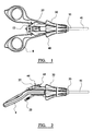
Figure 1 is a plan view of a laparoscopic forceps handle in accordance with the present invention; -
Figure 2 is a side elevation of the forceps shown inFigure 1 ; -
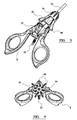
Figure 3 is an isometric view of the forceps shown inFigure 1 ; -
Figure 4 is a front elevation of the forceps shown inFigure 1 ; -
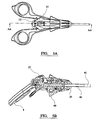
Figure 5 is a cross-sectional view on AA-AA; -
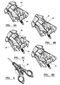
Figure 6 is a series of partial views illustrating operation of the ratchet mechanism; and -
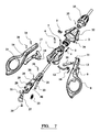
Figure 7 is an exploded view of forceps in accordance with this invention. - A laparoscopic forceps in accordance with this invention is illustrated in
Figures 1 to 7 . The handle described in greater detail below, is connected to thetubular support 41 which carries a conventional jaws assembly (not shown) wherein a pair of jaws mounted on a yoke are actuated by anactuation rod 42 extending within thetubular support 41 from a coupling with acore index sleeve 2. The tubular support and jaws assembly may be obtained from various commercial sources. The tubular support is releasably fastened to the handle by auniversal nut 35. - The handle comprises a
core 1 defining a longitudinal channel within which the electro-cautery connection core index sleeve 2 includes a rotatable bearing and releasable coupling to theactuation rod 42. - Moulded plastics right and
left scissor bows metal bow inserts core 1 bypins Linkages pins connection piece 21 by means of apin 24 so that opening of the bows causes the actuation rod to be retracted and the jaws to open. - The
bows Figures 2 and4 . The angle is selected so that the forceps extend generally coaxially of a user's forearm. This is convenient because the forceps can be rotated simply by rotation of the surgeon's wrist. - The
cautery insert rod 22 extends downwards from the centre of the handle generally parallel to thebows rod 22 passes conveniently below a surgeon's wrist in use. - A
conical sleeve 32 disposed frowardly of thecore 1 and switch assembly is coupled by apin 34 to thebearing 2.Radial projections 40 are dimensioned so that the index finger may fit snugly between adjacent projections to facilitate rotation of the forceps jaws through an angle up to 180° in a single movement. - The
profile release members switch 27 is disposed behind acomplementary surface 46 of theslideable member 25. Aplunger 28 andspring 29 engage recesses insurface 46 to provide positive engagement of the switch in the left and right positions. -
Ratchet 19 andpawl 12 are received in recesses in thebars Ratchet 19 is fixed butpawl 12 is pivotally connected by apin 13 and bias forwardly by thepawl return spring 14. The teeth of theratchet 19 are arranged so that when pawl 12 engages the ratchet the jaws may be closed but not opened. - The ratchet may be released by rearward movement of the
slideable release member 25 which carries aswitch 27 secured to the rear end thereof bypin 31. Themember 25 is slidably mounted on longitudinal formations on each side ofcore 1. Rearward movement ofmember 25 by pressure on theforward facing surface 43 moves theswitch 22 rearwardly. -
Switch 27 has a downwardly depending pin orstud 30 which acts as a pawl release guide. Thepin 30 is laterally offset so that left to right movement of the switch moves the pin rearwardly and movement from right to left moves the pin forwardly. Thepin 30 engages the forward surface ofpawl member 12 to form a cam and cam follower arrangement. - The operation of the forceps handle is described with reference to
Figures 6 and7 .Figures 6a to 6d show partial views of the switch assembly B. - In
Figure 6a theswitch 27 is in the right-hand position. Theplunger 28 is engaged in theright hand recess 47 insurface 46. - The
pin 30 is at the most rearwardly position and bears against the forward surface ofpawl member 12 disengaging the latter from theratchet 19. - Movement of the
switch 27 to the left, as shown inFigure 6c movespin 30forwardly allowing spring 14 to urge the pawl into engagement with the ratchet preventing opening of the forceps jaws. Movement of theswitch 27 to the right as shown inFigure 6d releases the pawl permitting opening of the jaws. -
Figure 6b illustrates a quick temporary release of the pawl by slidingmember 25 in a rearward direction.Pin 30 pushes pawl 12 directly rearwardly allowing free use of the jaws. Release of themember 25 re-engages the ratchet mechanism.
Claims (11)
- A laparoscopic forceps which comprises:a handle which comprises left and right bow members (15, 8) pivotally connected to a mounting core (1) in a scissors-like arrangement, and adapted to engage a user's finger and thumb in use;a tubular housing (41) extending from the handle and carrying an actuator rod (42) (42), defining the forceps axis;a switchable ratchet mechanism (12, 19) which can be moved between locked and unlocked positions, and which, when locked, allows closure and prevents opening of the jaws and, when unlocked, allows free opening and closing of the jaws, in which the ratchet mechanism includes a switch member (27),wherein the forceps includes a jaws mechanism disposed at the end of the tubular housing remote from the handle engaged to the actuator rod and arranged so that the jaws may be opened or closed by actuation of the handle;
characterised in that the switch member (27) extends longitudinally of the handle and is mounted on the handle by means of a pivot at the end thereof which is closest to the user between the bow members, so that it can be moved laterally relative to the forceps axis about the pivot between a first position in which the ratchet mechanism is locked and a second position in which the ratchet mechanism is unlocked, and in which the switch member is secured by the pivot to a release member (25) which can slide relative to the mounting core between a forward first position in which the ratchet mechanism is locked and a rearward second position closer to the user in which the ratchet mechanism is unlocked. - A laparoscopic forceps as claimed in claim 1, wherein the ratchet mechanism includes a ratchet (19) carried by the first bow member (15) and a pawl (12) carried by the second bow member (8), the ratchet and pawl being engaged in the locked position of the mechanism and disengaged in the unlocked position.
- A laparoscopic forceps as claimed in claim 2, wherein a spring (14) is arranged to urge the pawl (12) into engagement with the ratchet (19).
- A laparoscopic forceps as claimed in claim 3, wherein the switch member (27) includes a formation adapted to form a cam surface extending rearwardly of the pivot to engage a surface of the pawl (12) adapted to form a cam follower; arranged so that the movement of the switch member from the locked to unlocked position urges the pawl away from the ratchet (19) against the action of the spring (14) to disengage the pawl and ratchet.
- A laparoscopic forceps as claimed in claim 4, wherein the cam surface comprises a pin or stud (30) depending from the body of the switch member.
- A laparoscopic forceps as claimed in any of claims 1 to 3, wherein the switch member (27) engages the ratchet (19) in use to urge the latter out of engagement with the pawl (12).
- A laparoscopic forceps as claimed in claim 1, wherein the release member (25) has an upward projection defining a forwardly facing finger grip or other manual engagement surface.
- A laparoscopic forceps as claimed in claim 7, wherein the release member (25) and switch member (27) are disposed longitudinally on the upper centre portion of the handle.
- A laparoscopic forceps as claimed in claim 8, wherein the forward facing engagement surface of the release member and upper surface of the switch member (27) define a continuous, smooth profile.
- A laparoscopic forceps as claimed in any preceding claim, including a rotatable sleeve (32) forward of the switch and release members (25), the sleeve being connected to the actuator rod (42) so that rotation of the sleeve causes rotation of the jaws.
- A laparoscopic forceps as claimed in claim 10, wherein the sleeve (32) is provided with radial projections dimensioned to define finger engaging recesses between adjacent projections.
Applications Claiming Priority (3)
| Application Number | Priority Date | Filing Date | Title |
|---|---|---|---|
| GBGB9919722.0A GB9919722D0 (en) | 1999-08-20 | 1999-08-20 | Laparoscopic forceps handle |
| GB9919722 | 1999-08-20 | ||
| PCT/GB2000/003229 WO2001013803A1 (en) | 1999-08-20 | 2000-08-21 | Laparoscopic forceps handle |
Publications (2)
| Publication Number | Publication Date |
|---|---|
| EP1204380A1 EP1204380A1 (en) | 2002-05-15 |
| EP1204380B1 true EP1204380B1 (en) | 2008-12-10 |
Family
ID=10859492
Family Applications (1)
| Application Number | Title | Priority Date | Filing Date |
|---|---|---|---|
| EP00954742A Expired - Lifetime EP1204380B1 (en) | 1999-08-20 | 2000-08-21 | Laparoscopic forceps |
Country Status (9)
| Country | Link |
|---|---|
| US (1) | US6641595B1 (en) |
| EP (1) | EP1204380B1 (en) |
| JP (1) | JP4364472B2 (en) |
| AT (1) | ATE416695T1 (en) |
| AU (1) | AU6710000A (en) |
| CA (1) | CA2382219C (en) |
| DE (1) | DE60041063D1 (en) |
| GB (1) | GB9919722D0 (en) |
| WO (1) | WO2001013803A1 (en) |
Families Citing this family (149)
| Publication number | Priority date | Publication date | Assignee | Title |
|---|---|---|---|---|
| US7435249B2 (en) | 1997-11-12 | 2008-10-14 | Covidien Ag | Electrosurgical instruments which reduces collateral damage to adjacent tissue |
| US6726686B2 (en) | 1997-11-12 | 2004-04-27 | Sherwood Services Ag | Bipolar electrosurgical instrument for sealing vessels |
| US6228083B1 (en) | 1997-11-14 | 2001-05-08 | Sherwood Services Ag | Laparoscopic bipolar electrosurgical instrument |
| US20030014052A1 (en) | 1997-11-14 | 2003-01-16 | Buysse Steven P. | Laparoscopic bipolar electrosurgical instrument |
| US7267677B2 (en) | 1998-10-23 | 2007-09-11 | Sherwood Services Ag | Vessel sealing instrument |
| US20040249374A1 (en) | 1998-10-23 | 2004-12-09 | Tetzlaff Philip M. | Vessel sealing instrument |
| US7364577B2 (en) | 2002-02-11 | 2008-04-29 | Sherwood Services Ag | Vessel sealing system |
| US7582087B2 (en) | 1998-10-23 | 2009-09-01 | Covidien Ag | Vessel sealing instrument |
| US7118570B2 (en) | 2001-04-06 | 2006-10-10 | Sherwood Services Ag | Vessel sealing forceps with disposable electrodes |
| US7887535B2 (en) | 1999-10-18 | 2011-02-15 | Covidien Ag | Vessel sealing wave jaw |
| US20030109875A1 (en) | 1999-10-22 | 2003-06-12 | Tetzlaff Philip M. | Open vessel sealing forceps with disposable electrodes |
| JP4394881B2 (en) | 2001-04-06 | 2010-01-06 | コヴィディエン アクチェンゲゼルシャフト | An electrosurgical instrument that reduces incidental damage to adjacent tissue |
| US10849681B2 (en) | 2001-04-06 | 2020-12-01 | Covidien Ag | Vessel sealer and divider |
| US7101371B2 (en) | 2001-04-06 | 2006-09-05 | Dycus Sean T | Vessel sealer and divider |
| CA2442960C (en) | 2001-04-06 | 2011-03-22 | Sherwood Services Ag | Vessel sealing instrument |
| US7101372B2 (en) | 2001-04-06 | 2006-09-05 | Sherwood Sevices Ag | Vessel sealer and divider |
| DE60121229T2 (en) | 2001-04-06 | 2007-05-24 | Sherwood Services Ag | DEVICE FOR SEALING AND SHARING A VESSEL WITH NON-LASTING END STOP |
| US7276068B2 (en) | 2002-10-04 | 2007-10-02 | Sherwood Services Ag | Vessel sealing instrument with electrical cutting mechanism |
| US7270664B2 (en) | 2002-10-04 | 2007-09-18 | Sherwood Services Ag | Vessel sealing instrument with electrical cutting mechanism |
| US7931649B2 (en) | 2002-10-04 | 2011-04-26 | Tyco Healthcare Group Lp | Vessel sealing instrument with electrical cutting mechanism |
| US7799026B2 (en) | 2002-11-14 | 2010-09-21 | Covidien Ag | Compressible jaw configuration with bipolar RF output electrodes for soft tissue fusion |
| US7033354B2 (en) | 2002-12-10 | 2006-04-25 | Sherwood Services Ag | Electrosurgical electrode having a non-conductive porous ceramic coating |
| AU2003223284C1 (en) | 2003-03-13 | 2010-09-16 | Covidien Ag | Bipolar concentric electrode assembly for soft tissue fusion |
| US8128624B2 (en) | 2003-05-01 | 2012-03-06 | Covidien Ag | Electrosurgical instrument that directs energy delivery and protects adjacent tissue |
| US7147638B2 (en) | 2003-05-01 | 2006-12-12 | Sherwood Services Ag | Electrosurgical instrument which reduces thermal damage to adjacent tissue |
| US7160299B2 (en) | 2003-05-01 | 2007-01-09 | Sherwood Services Ag | Method of fusing biomaterials with radiofrequency energy |
| WO2004103156A2 (en) | 2003-05-15 | 2004-12-02 | Sherwood Services Ag | Tissue sealer with non-conductive variable stop members and method of sealing tissue |
| USD956973S1 (en) | 2003-06-13 | 2022-07-05 | Covidien Ag | Movable handle for endoscopic vessel sealer and divider |
| US7150749B2 (en) | 2003-06-13 | 2006-12-19 | Sherwood Services Ag | Vessel sealer and divider having elongated knife stroke and safety cutting mechanism |
| US7597693B2 (en) | 2003-06-13 | 2009-10-06 | Covidien Ag | Vessel sealer and divider for use with small trocars and cannulas |
| US7857812B2 (en) | 2003-06-13 | 2010-12-28 | Covidien Ag | Vessel sealer and divider having elongated knife stroke and safety for cutting mechanism |
| US7156846B2 (en) | 2003-06-13 | 2007-01-02 | Sherwood Services Ag | Vessel sealer and divider for use with small trocars and cannulas |
| US7709754B2 (en) | 2003-08-26 | 2010-05-04 | Allegro Microsystems, Inc. | Current sensor |
| US9848938B2 (en) | 2003-11-13 | 2017-12-26 | Covidien Ag | Compressible jaw configuration with bipolar RF output electrodes for soft tissue fusion |
| US7232440B2 (en) | 2003-11-17 | 2007-06-19 | Sherwood Services Ag | Bipolar forceps having monopolar extension |
| US7367976B2 (en) | 2003-11-17 | 2008-05-06 | Sherwood Services Ag | Bipolar forceps having monopolar extension |
| US7811283B2 (en) | 2003-11-19 | 2010-10-12 | Covidien Ag | Open vessel sealing instrument with hourglass cutting mechanism and over-ratchet safety |
| US7500975B2 (en) | 2003-11-19 | 2009-03-10 | Covidien Ag | Spring loaded reciprocating tissue cutting mechanism in a forceps-style electrosurgical instrument |
| US7131970B2 (en) | 2003-11-19 | 2006-11-07 | Sherwood Services Ag | Open vessel sealing instrument with cutting mechanism |
| US7442193B2 (en) | 2003-11-20 | 2008-10-28 | Covidien Ag | Electrically conductive/insulative over-shoe for tissue fusion |
| US7780662B2 (en) | 2004-03-02 | 2010-08-24 | Covidien Ag | Vessel sealing system using capacitive RF dielectric heating |
| US7491207B2 (en) * | 2004-04-12 | 2009-02-17 | Synthes Usa, Llc | Rod persuader |
| EP1841374A2 (en) * | 2004-07-06 | 2007-10-10 | Synthes GmbH | Spinal rod insertion instrument |
| US7195631B2 (en) | 2004-09-09 | 2007-03-27 | Sherwood Services Ag | Forceps with spring loaded end effector assembly |
| US7540872B2 (en) | 2004-09-21 | 2009-06-02 | Covidien Ag | Articulating bipolar electrosurgical instrument |
| US7384421B2 (en) | 2004-10-06 | 2008-06-10 | Sherwood Services Ag | Slide-activated cutting assembly |
| US7628792B2 (en) | 2004-10-08 | 2009-12-08 | Covidien Ag | Bilateral foot jaws |
| US7955332B2 (en) | 2004-10-08 | 2011-06-07 | Covidien Ag | Mechanism for dividing tissue in a hemostat-style instrument |
| US7686827B2 (en) | 2004-10-21 | 2010-03-30 | Covidien Ag | Magnetic closure mechanism for hemostat |
| US7686804B2 (en) | 2005-01-14 | 2010-03-30 | Covidien Ag | Vessel sealer and divider with rotating sealer and cutter |
| US7909823B2 (en) | 2005-01-14 | 2011-03-22 | Covidien Ag | Open vessel sealing instrument |
| US7491202B2 (en) | 2005-03-31 | 2009-02-17 | Covidien Ag | Electrosurgical forceps with slow closure sealing plates and method of sealing tissue |
| US7837685B2 (en) | 2005-07-13 | 2010-11-23 | Covidien Ag | Switch mechanisms for safe activation of energy on an electrosurgical instrument |
| US7628791B2 (en) | 2005-08-19 | 2009-12-08 | Covidien Ag | Single action tissue sealer |
| US7879035B2 (en) | 2005-09-30 | 2011-02-01 | Covidien Ag | Insulating boot for electrosurgical forceps |
| US7722607B2 (en) | 2005-09-30 | 2010-05-25 | Covidien Ag | In-line vessel sealer and divider |
| US7789878B2 (en) | 2005-09-30 | 2010-09-07 | Covidien Ag | In-line vessel sealer and divider |
| CA2561034C (en) | 2005-09-30 | 2014-12-09 | Sherwood Services Ag | Flexible endoscopic catheter with an end effector for coagulating and transfecting tissue |
| US7922953B2 (en) | 2005-09-30 | 2011-04-12 | Covidien Ag | Method for manufacturing an end effector assembly |
| ES2381560T3 (en) | 2005-09-30 | 2012-05-29 | Covidien Ag | Insulating sleeve for electrosurgical forceps |
| US7594916B2 (en) | 2005-11-22 | 2009-09-29 | Covidien Ag | Electrosurgical forceps with energy based tissue division |
| US8734443B2 (en) | 2006-01-24 | 2014-05-27 | Covidien Lp | Vessel sealer and divider for large tissue structures |
| US8241282B2 (en) | 2006-01-24 | 2012-08-14 | Tyco Healthcare Group Lp | Vessel sealing cutting assemblies |
| US7766910B2 (en) | 2006-01-24 | 2010-08-03 | Tyco Healthcare Group Lp | Vessel sealer and divider for large tissue structures |
| US8882766B2 (en) | 2006-01-24 | 2014-11-11 | Covidien Ag | Method and system for controlling delivery of energy to divide tissue |
| US8298232B2 (en) | 2006-01-24 | 2012-10-30 | Tyco Healthcare Group Lp | Endoscopic vessel sealer and divider for large tissue structures |
| US7641653B2 (en) | 2006-05-04 | 2010-01-05 | Covidien Ag | Open vessel sealing forceps disposable handswitch |
| US7846158B2 (en) | 2006-05-05 | 2010-12-07 | Covidien Ag | Apparatus and method for electrode thermosurgery |
| US7846177B2 (en) * | 2006-06-26 | 2010-12-07 | Carefusion 2200, Inc. | Surgical device |
| US7776037B2 (en) | 2006-07-07 | 2010-08-17 | Covidien Ag | System and method for controlling electrode gap during tissue sealing |
| US7744615B2 (en) | 2006-07-18 | 2010-06-29 | Covidien Ag | Apparatus and method for transecting tissue on a bipolar vessel sealing instrument |
| US8597297B2 (en) | 2006-08-29 | 2013-12-03 | Covidien Ag | Vessel sealing instrument with multiple electrode configurations |
| US8070746B2 (en) * | 2006-10-03 | 2011-12-06 | Tyco Healthcare Group Lp | Radiofrequency fusion of cardiac tissue |
| US7951149B2 (en) | 2006-10-17 | 2011-05-31 | Tyco Healthcare Group Lp | Ablative material for use with tissue treatment device |
| USD575395S1 (en) | 2007-02-15 | 2008-08-19 | Tyco Healthcare Group Lp | Hemostat style elongated dissecting and dividing instrument |
| US8267935B2 (en) | 2007-04-04 | 2012-09-18 | Tyco Healthcare Group Lp | Electrosurgical instrument reducing current densities at an insulator conductor junction |
| USD575401S1 (en) | 2007-06-12 | 2008-08-19 | Tyco Healthcare Group Lp | Vessel sealer |
| US7877853B2 (en) | 2007-09-20 | 2011-02-01 | Tyco Healthcare Group Lp | Method of manufacturing end effector assembly for sealing tissue |
| US7877852B2 (en) | 2007-09-20 | 2011-02-01 | Tyco Healthcare Group Lp | Method of manufacturing an end effector assembly for sealing tissue |
| US8251996B2 (en) | 2007-09-28 | 2012-08-28 | Tyco Healthcare Group Lp | Insulating sheath for electrosurgical forceps |
| US8235993B2 (en) | 2007-09-28 | 2012-08-07 | Tyco Healthcare Group Lp | Insulating boot for electrosurgical forceps with exohinged structure |
| US9023043B2 (en) | 2007-09-28 | 2015-05-05 | Covidien Lp | Insulating mechanically-interfaced boot and jaws for electrosurgical forceps |
| US8235992B2 (en) | 2007-09-28 | 2012-08-07 | Tyco Healthcare Group Lp | Insulating boot with mechanical reinforcement for electrosurgical forceps |
| US8236025B2 (en) | 2007-09-28 | 2012-08-07 | Tyco Healthcare Group Lp | Silicone insulated electrosurgical forceps |
| US8267936B2 (en) | 2007-09-28 | 2012-09-18 | Tyco Healthcare Group Lp | Insulating mechanically-interfaced adhesive for electrosurgical forceps |
| US8221416B2 (en) | 2007-09-28 | 2012-07-17 | Tyco Healthcare Group Lp | Insulating boot for electrosurgical forceps with thermoplastic clevis |
| AU2008221509B2 (en) | 2007-09-28 | 2013-10-10 | Covidien Lp | Dual durometer insulating boot for electrosurgical forceps |
| AU2008329676B2 (en) | 2007-11-26 | 2015-03-05 | Attractive Surgical, Llc | Magnaretractor system and method |
| WO2009092132A1 (en) * | 2008-01-22 | 2009-07-30 | James Anthony Castley | A hand held implement |
| US8764748B2 (en) | 2008-02-06 | 2014-07-01 | Covidien Lp | End effector assembly for electrosurgical device and method for making the same |
| US8623276B2 (en) | 2008-02-15 | 2014-01-07 | Covidien Lp | Method and system for sterilizing an electrosurgical instrument |
| US8469956B2 (en) | 2008-07-21 | 2013-06-25 | Covidien Lp | Variable resistor jaw |
| US8801752B2 (en) * | 2008-08-04 | 2014-08-12 | Covidien Lp | Articulating surgical device |
| US8162973B2 (en) | 2008-08-15 | 2012-04-24 | Tyco Healthcare Group Lp | Method of transferring pressure in an articulating surgical instrument |
| US8257387B2 (en) | 2008-08-15 | 2012-09-04 | Tyco Healthcare Group Lp | Method of transferring pressure in an articulating surgical instrument |
| US9603652B2 (en) | 2008-08-21 | 2017-03-28 | Covidien Lp | Electrosurgical instrument including a sensor |
| US8795274B2 (en) | 2008-08-28 | 2014-08-05 | Covidien Lp | Tissue fusion jaw angle improvement |
| US8784417B2 (en) | 2008-08-28 | 2014-07-22 | Covidien Lp | Tissue fusion jaw angle improvement |
| US8317787B2 (en) | 2008-08-28 | 2012-11-27 | Covidien Lp | Tissue fusion jaw angle improvement |
| US8303582B2 (en) | 2008-09-15 | 2012-11-06 | Tyco Healthcare Group Lp | Electrosurgical instrument having a coated electrode utilizing an atomic layer deposition technique |
| US8535312B2 (en) | 2008-09-25 | 2013-09-17 | Covidien Lp | Apparatus, system and method for performing an electrosurgical procedure |
| US8968314B2 (en) | 2008-09-25 | 2015-03-03 | Covidien Lp | Apparatus, system and method for performing an electrosurgical procedure |
| US9375254B2 (en) | 2008-09-25 | 2016-06-28 | Covidien Lp | Seal and separate algorithm |
| US8142473B2 (en) | 2008-10-03 | 2012-03-27 | Tyco Healthcare Group Lp | Method of transferring rotational motion in an articulating surgical instrument |
| US8469957B2 (en) | 2008-10-07 | 2013-06-25 | Covidien Lp | Apparatus, system, and method for performing an electrosurgical procedure |
| US8016827B2 (en) | 2008-10-09 | 2011-09-13 | Tyco Healthcare Group Lp | Apparatus, system, and method for performing an electrosurgical procedure |
| US8636761B2 (en) | 2008-10-09 | 2014-01-28 | Covidien Lp | Apparatus, system, and method for performing an endoscopic electrosurgical procedure |
| US8486107B2 (en) | 2008-10-20 | 2013-07-16 | Covidien Lp | Method of sealing tissue using radiofrequency energy |
| US20100137845A1 (en) * | 2008-12-03 | 2010-06-03 | Immersion Corporation | Tool Having Multiple Feedback Devices |
| US8197479B2 (en) | 2008-12-10 | 2012-06-12 | Tyco Healthcare Group Lp | Vessel sealer and divider |
| US8114122B2 (en) | 2009-01-13 | 2012-02-14 | Tyco Healthcare Group Lp | Apparatus, system, and method for performing an electrosurgical procedure |
| US8187273B2 (en) | 2009-05-07 | 2012-05-29 | Tyco Healthcare Group Lp | Apparatus, system, and method for performing an electrosurgical procedure |
| US8246618B2 (en) | 2009-07-08 | 2012-08-21 | Tyco Healthcare Group Lp | Electrosurgical jaws with offset knife |
| US8133254B2 (en) | 2009-09-18 | 2012-03-13 | Tyco Healthcare Group Lp | In vivo attachable and detachable end effector assembly and laparoscopic surgical instrument and methods therefor |
| US8112871B2 (en) | 2009-09-28 | 2012-02-14 | Tyco Healthcare Group Lp | Method for manufacturing electrosurgical seal plates |
| WO2011044560A2 (en) | 2009-10-09 | 2011-04-14 | Applied Medical Resources Corporation | Single port instruments |
| US9113940B2 (en) | 2011-01-14 | 2015-08-25 | Covidien Lp | Trigger lockout and kickback mechanism for surgical instruments |
| GB2490151B (en) * | 2011-04-20 | 2018-03-28 | Surgical Innovations Ltd | Surgical instrument insert and surgical instrument system |
| USD680220S1 (en) | 2012-01-12 | 2013-04-16 | Coviden IP | Slider handle for laparoscopic device |
| US8629539B2 (en) | 2012-01-16 | 2014-01-14 | Allegro Microsystems, Llc | Methods and apparatus for magnetic sensor having non-conductive die paddle |
| US8679140B2 (en) | 2012-05-30 | 2014-03-25 | Covidien Lp | Surgical clamping device with ratcheting grip lock |
| DE102012110260B4 (en) * | 2012-10-26 | 2018-10-11 | Karl Storz Se & Co. Kg | Operating handle for a microsurgical instrument |
| US8764769B1 (en) | 2013-03-12 | 2014-07-01 | Levita Magnetics International Corp. | Grasper with magnetically-controlled positioning |
| WO2014143472A1 (en) | 2013-03-15 | 2014-09-18 | GYRUS ACMI, INC. (d/b/a OLYMPUS SURGICAL TECHNOLOGIES AMERICA) | Electrosurgical instrument |
| EP3427682B1 (en) | 2013-03-15 | 2020-09-23 | Gyrus ACMI, Inc. (D.B.A. Olympus Surgical Technologies America) | Combination electrosurgical device |
| CN105025833B (en) | 2013-03-15 | 2017-11-21 | 捷锐士阿希迈公司(以奥林巴斯美国外科技术名义) | Combined Electrosurgical Equipment |
| CN108078625B (en) | 2013-03-15 | 2020-11-17 | 捷锐士阿希迈公司(以奥林巴斯美国外科技术名义) | Offset surgical forceps |
| EP2974682B1 (en) | 2013-03-15 | 2017-08-30 | Gyrus ACMI, Inc. | Combination electrosurgical device |
| CN105451670B (en) | 2013-08-07 | 2018-09-04 | 柯惠有限合伙公司 | Surgery forceps |
| EP3096673B1 (en) | 2014-01-21 | 2025-02-19 | Levita Magnetics International Corp. | Laparoscopic graspers and systems therefor |
| CN106659534B (en) | 2014-08-20 | 2020-03-17 | 捷锐士阿希迈公司(以奥林巴斯美国外科技术名义) | Reconfigurable electrosurgical device |
| US10231777B2 (en) | 2014-08-26 | 2019-03-19 | Covidien Lp | Methods of manufacturing jaw members of an end-effector assembly for a surgical instrument |
| EP3273892B1 (en) | 2015-03-23 | 2019-10-16 | Gyrus ACMI, Inc. (D.B.A. Olympus Surgical Technologies America) | Medical forceps with vessel transection capability |
| EP3282954B1 (en) | 2015-04-13 | 2021-07-28 | Levita Magnetics International Corp. | Grasper with magnetically-controlled positioning |
| ES2897754T3 (en) | 2015-04-13 | 2022-03-02 | Levita Magnetics Int Corp | retraction devices |
| US9987078B2 (en) | 2015-07-22 | 2018-06-05 | Covidien Lp | Surgical forceps |
| WO2017031712A1 (en) | 2015-08-26 | 2017-03-02 | Covidien Lp | Electrosurgical end effector assemblies and electrosurgical forceps configured to reduce thermal spread |
| USD796042S1 (en) | 2015-08-31 | 2017-08-29 | Adventist Health System/Sunbelt, Inc. | Handle for laparoscopic surgery instrument |
| US10213250B2 (en) | 2015-11-05 | 2019-02-26 | Covidien Lp | Deployment and safety mechanisms for surgical instruments |
| WO2017120540A1 (en) | 2016-01-08 | 2017-07-13 | Levita Magnetics International Corp. | One-operator surgical system and methods of use |
| JP6683368B2 (en) * | 2016-03-31 | 2020-04-22 | 国立大学法人鳥取大学 | Medical forceps |
| US10856933B2 (en) | 2016-08-02 | 2020-12-08 | Covidien Lp | Surgical instrument housing incorporating a channel and methods of manufacturing the same |
| US10918407B2 (en) | 2016-11-08 | 2021-02-16 | Covidien Lp | Surgical instrument for grasping, treating, and/or dividing tissue |
| US11020137B2 (en) | 2017-03-20 | 2021-06-01 | Levita Magnetics International Corp. | Directable traction systems and methods |
| US11166759B2 (en) | 2017-05-16 | 2021-11-09 | Covidien Lp | Surgical forceps |
| US11383373B2 (en) | 2017-11-02 | 2022-07-12 | Gyms Acmi, Inc. | Bias device for biasing a gripping device by biasing working arms apart |
| US11298801B2 (en) | 2017-11-02 | 2022-04-12 | Gyrus Acmi, Inc. | Bias device for biasing a gripping device including a central body and shuttles on the working arms |
| US10667834B2 (en) | 2017-11-02 | 2020-06-02 | Gyrus Acmi, Inc. | Bias device for biasing a gripping device with a shuttle on a central body |
| DE102023122446A1 (en) * | 2023-08-22 | 2025-02-27 | Aesculap Ag | butterfly handle of a surgical hand instrument |
Family Cites Families (7)
| Publication number | Priority date | Publication date | Assignee | Title |
|---|---|---|---|---|
| US5176702A (en) | 1991-04-04 | 1993-01-05 | Symbiosis Corporation | Ratchet locking mechanism for surgical instruments |
| FR2682278B1 (en) * | 1991-10-15 | 1998-11-06 | Boutmy Ets | SURGICAL INSTRUMENT PROVIDED WITH SYMMETRICAL MEANS OF OPERATION. |
| FR2688681A1 (en) | 1992-03-23 | 1993-09-24 | Lebosse Guy | Universal handle for coeliosurgery instrumentation |
| US5251638A (en) | 1992-04-16 | 1993-10-12 | Cordis Corporation | Biopsy forceps device having improved handle assembly |
| JPH06296618A (en) * | 1993-04-14 | 1994-10-25 | Olympus Optical Co Ltd | Clamping forceps |
| US5700270A (en) | 1995-10-20 | 1997-12-23 | United States Surgical Corporation | Surgical clip applier |
| JPH10127654A (en) * | 1996-11-05 | 1998-05-19 | Olympus Optical Co Ltd | Ultrasonic treatment tool |
-
1999
- 1999-08-20 GB GBGB9919722.0A patent/GB9919722D0/en not_active Ceased
-
2000
- 2000-06-01 US US09/586,677 patent/US6641595B1/en not_active Expired - Lifetime
- 2000-08-21 CA CA002382219A patent/CA2382219C/en not_active Expired - Fee Related
- 2000-08-21 AT AT00954742T patent/ATE416695T1/en not_active IP Right Cessation
- 2000-08-21 WO PCT/GB2000/003229 patent/WO2001013803A1/en not_active Ceased
- 2000-08-21 DE DE60041063T patent/DE60041063D1/en not_active Expired - Lifetime
- 2000-08-21 AU AU67100/00A patent/AU6710000A/en not_active Abandoned
- 2000-08-21 EP EP00954742A patent/EP1204380B1/en not_active Expired - Lifetime
- 2000-08-21 JP JP2001517948A patent/JP4364472B2/en not_active Expired - Fee Related
Also Published As
| Publication number | Publication date |
|---|---|
| JP2003507118A (en) | 2003-02-25 |
| CA2382219C (en) | 2009-11-03 |
| EP1204380A1 (en) | 2002-05-15 |
| WO2001013803A1 (en) | 2001-03-01 |
| ATE416695T1 (en) | 2008-12-15 |
| AU6710000A (en) | 2001-03-19 |
| DE60041063D1 (en) | 2009-01-22 |
| US6641595B1 (en) | 2003-11-04 |
| JP4364472B2 (en) | 2009-11-18 |
| GB9919722D0 (en) | 1999-10-20 |
| CA2382219A1 (en) | 2001-03-01 |
Similar Documents
| Publication | Publication Date | Title |
|---|---|---|
| CA2382219C (en) | Laparoscopic forceps handle | |
| EP0813843B1 (en) | Variable position handle locking mechanism | |
| US6299625B1 (en) | Handle for a medical instrument | |
| US5928263A (en) | Surgical instrument with flexible actuator and rigid actuator cover | |
| US6129740A (en) | Instrument handle design | |
| US5281220A (en) | Endoscopic instrument | |
| US5483952A (en) | Handle for surgical instruments | |
| US6057518A (en) | Lockout mechanism for power tool | |
| US5665105A (en) | Radially adjustable surgical instrument for heart surgery | |
| CA2103507C (en) | Locking mechanism for endoscopic or laparoscopic surgical instruments | |
| US5308357A (en) | Handle mechanism for manual instruments | |
| US5797956A (en) | Surgical instrument handle and actuator means for heart surgery | |
| US20060206144A1 (en) | Medical instrument with actuating handle | |
| GB2460392A (en) | Surgical instrument handle with adjustable finger grip | |
| WO2004091377A3 (en) | Surgical instrument with trigger control | |
| US3814102A (en) | Surgical instrument | |
| US5827263A (en) | Surgical instrument handle | |
| US20040073254A1 (en) | Suture retriever with in-line actuating handle | |
| CN105188573A (en) | Forceps with continuous latch | |
| JP3996353B2 (en) | forceps |
Legal Events
| Date | Code | Title | Description |
|---|---|---|---|
| PUAI | Public reference made under article 153(3) epc to a published international application that has entered the european phase |
Free format text: ORIGINAL CODE: 0009012 |
|
| 17P | Request for examination filed |
Effective date: 20020214 |
|
| AK | Designated contracting states |
Kind code of ref document: A1 Designated state(s): AT BE CH CY DE DK ES FI FR GB GR IE IT LI LU MC NL PT SE |
|
| AX | Request for extension of the european patent |
Free format text: AL PAYMENT 20020214;LT PAYMENT 20020214;LV PAYMENT 20020214;MK PAYMENT 20020214;RO PAYMENT 20020214;SI PAYMENT 20020214 |
|
| 17Q | First examination report despatched |
Effective date: 20061212 |
|
| GRAP | Despatch of communication of intention to grant a patent |
Free format text: ORIGINAL CODE: EPIDOSNIGR1 |
|
| RTI1 | Title (correction) |
Free format text: LAPAROSCOPIC FORCEPS |
|
| GRAS | Grant fee paid |
Free format text: ORIGINAL CODE: EPIDOSNIGR3 |
|
| GRAA | (expected) grant |
Free format text: ORIGINAL CODE: 0009210 |
|
| AK | Designated contracting states |
Kind code of ref document: B1 Designated state(s): AT BE CH CY DE DK ES FI FR GB GR IE IT LI LU MC NL PT SE |
|
| AX | Request for extension of the european patent |
Extension state: AL LT LV MK RO SI |
|
| REG | Reference to a national code |
Ref country code: GB Ref legal event code: FG4D |
|
| REG | Reference to a national code |
Ref country code: CH Ref legal event code: EP |
|
| REG | Reference to a national code |
Ref country code: IE Ref legal event code: FG4D |
|
| REF | Corresponds to: |
Ref document number: 60041063 Country of ref document: DE Date of ref document: 20090122 Kind code of ref document: P |
|
| LTIE | Lt: invalidation of european patent or patent extension |
Effective date: 20081210 |
|
| PG25 | Lapsed in a contracting state [announced via postgrant information from national office to epo] |
Ref country code: NL Free format text: LAPSE BECAUSE OF FAILURE TO SUBMIT A TRANSLATION OF THE DESCRIPTION OR TO PAY THE FEE WITHIN THE PRESCRIBED TIME-LIMIT Effective date: 20081210 Ref country code: FI Free format text: LAPSE BECAUSE OF FAILURE TO SUBMIT A TRANSLATION OF THE DESCRIPTION OR TO PAY THE FEE WITHIN THE PRESCRIBED TIME-LIMIT Effective date: 20081210 |
|
| NLV1 | Nl: lapsed or annulled due to failure to fulfill the requirements of art. 29p and 29m of the patents act | ||
| PG25 | Lapsed in a contracting state [announced via postgrant information from national office to epo] |
Ref country code: BE Free format text: LAPSE BECAUSE OF FAILURE TO SUBMIT A TRANSLATION OF THE DESCRIPTION OR TO PAY THE FEE WITHIN THE PRESCRIBED TIME-LIMIT Effective date: 20081210 Ref country code: ES Free format text: LAPSE BECAUSE OF FAILURE TO SUBMIT A TRANSLATION OF THE DESCRIPTION OR TO PAY THE FEE WITHIN THE PRESCRIBED TIME-LIMIT Effective date: 20090321 |
|
| PG25 | Lapsed in a contracting state [announced via postgrant information from national office to epo] |
Ref country code: AT Free format text: LAPSE BECAUSE OF FAILURE TO SUBMIT A TRANSLATION OF THE DESCRIPTION OR TO PAY THE FEE WITHIN THE PRESCRIBED TIME-LIMIT Effective date: 20081210 Ref country code: PT Free format text: LAPSE BECAUSE OF FAILURE TO SUBMIT A TRANSLATION OF THE DESCRIPTION OR TO PAY THE FEE WITHIN THE PRESCRIBED TIME-LIMIT Effective date: 20090511 Ref country code: SE Free format text: LAPSE BECAUSE OF FAILURE TO SUBMIT A TRANSLATION OF THE DESCRIPTION OR TO PAY THE FEE WITHIN THE PRESCRIBED TIME-LIMIT Effective date: 20090310 |
|
| PLBE | No opposition filed within time limit |
Free format text: ORIGINAL CODE: 0009261 |
|
| STAA | Information on the status of an ep patent application or granted ep patent |
Free format text: STATUS: NO OPPOSITION FILED WITHIN TIME LIMIT |
|
| PG25 | Lapsed in a contracting state [announced via postgrant information from national office to epo] |
Ref country code: DK Free format text: LAPSE BECAUSE OF FAILURE TO SUBMIT A TRANSLATION OF THE DESCRIPTION OR TO PAY THE FEE WITHIN THE PRESCRIBED TIME-LIMIT Effective date: 20081210 |
|
| 26N | No opposition filed |
Effective date: 20090911 |
|
| PG25 | Lapsed in a contracting state [announced via postgrant information from national office to epo] |
Ref country code: MC Free format text: LAPSE BECAUSE OF NON-PAYMENT OF DUE FEES Effective date: 20090831 |
|
| REG | Reference to a national code |
Ref country code: CH Ref legal event code: PL |
|
| PG25 | Lapsed in a contracting state [announced via postgrant information from national office to epo] |
Ref country code: CH Free format text: LAPSE BECAUSE OF NON-PAYMENT OF DUE FEES Effective date: 20090831 Ref country code: LI Free format text: LAPSE BECAUSE OF NON-PAYMENT OF DUE FEES Effective date: 20090831 |
|
| PG25 | Lapsed in a contracting state [announced via postgrant information from national office to epo] |
Ref country code: IE Free format text: LAPSE BECAUSE OF NON-PAYMENT OF DUE FEES Effective date: 20090821 |
|
| PG25 | Lapsed in a contracting state [announced via postgrant information from national office to epo] |
Ref country code: GR Free format text: LAPSE BECAUSE OF FAILURE TO SUBMIT A TRANSLATION OF THE DESCRIPTION OR TO PAY THE FEE WITHIN THE PRESCRIBED TIME-LIMIT Effective date: 20090311 |
|
| PG25 | Lapsed in a contracting state [announced via postgrant information from national office to epo] |
Ref country code: LU Free format text: LAPSE BECAUSE OF NON-PAYMENT OF DUE FEES Effective date: 20090821 |
|
| PG25 | Lapsed in a contracting state [announced via postgrant information from national office to epo] |
Ref country code: CY Free format text: LAPSE BECAUSE OF FAILURE TO SUBMIT A TRANSLATION OF THE DESCRIPTION OR TO PAY THE FEE WITHIN THE PRESCRIBED TIME-LIMIT Effective date: 20081210 |
|
| PGFP | Annual fee paid to national office [announced via postgrant information from national office to epo] |
Ref country code: DE Payment date: 20140821 Year of fee payment: 15 |
|
| PGFP | Annual fee paid to national office [announced via postgrant information from national office to epo] |
Ref country code: FR Payment date: 20140821 Year of fee payment: 15 |
|
| PGFP | Annual fee paid to national office [announced via postgrant information from national office to epo] |
Ref country code: IT Payment date: 20140826 Year of fee payment: 15 |
|
| REG | Reference to a national code |
Ref country code: DE Ref legal event code: R119 Ref document number: 60041063 Country of ref document: DE |
|
| PG25 | Lapsed in a contracting state [announced via postgrant information from national office to epo] |
Ref country code: IT Free format text: LAPSE BECAUSE OF NON-PAYMENT OF DUE FEES Effective date: 20150821 |
|
| REG | Reference to a national code |
Ref country code: FR Ref legal event code: ST Effective date: 20160429 |
|
| PG25 | Lapsed in a contracting state [announced via postgrant information from national office to epo] |
Ref country code: DE Free format text: LAPSE BECAUSE OF NON-PAYMENT OF DUE FEES Effective date: 20160301 |
|
| PG25 | Lapsed in a contracting state [announced via postgrant information from national office to epo] |
Ref country code: FR Free format text: LAPSE BECAUSE OF NON-PAYMENT OF DUE FEES Effective date: 20150831 |
|
| PGFP | Annual fee paid to national office [announced via postgrant information from national office to epo] |
Ref country code: GB Payment date: 20190722 Year of fee payment: 20 |
|
| REG | Reference to a national code |
Ref country code: GB Ref legal event code: PE20 Expiry date: 20200820 |
|
| PG25 | Lapsed in a contracting state [announced via postgrant information from national office to epo] |
Ref country code: GB Free format text: LAPSE BECAUSE OF EXPIRATION OF PROTECTION Effective date: 20200820 |