EP1204251A2 - Designing interconnect fabrics of networks - Google Patents
Designing interconnect fabrics of networks Download PDFInfo
- Publication number
- EP1204251A2 EP1204251A2 EP01309079A EP01309079A EP1204251A2 EP 1204251 A2 EP1204251 A2 EP 1204251A2 EP 01309079 A EP01309079 A EP 01309079A EP 01309079 A EP01309079 A EP 01309079A EP 1204251 A2 EP1204251 A2 EP 1204251A2
- Authority
- EP
- European Patent Office
- Prior art keywords
- flow
- source
- port
- sets
- interconnect
- Prior art date
- Legal status (The legal status is an assumption and is not a legal conclusion. Google has not performed a legal analysis and makes no representation as to the accuracy of the status listed.)
- Withdrawn
Links
Images




Classifications
-
- H—ELECTRICITY
- H04—ELECTRIC COMMUNICATION TECHNIQUE
- H04L—TRANSMISSION OF DIGITAL INFORMATION, e.g. TELEGRAPHIC COMMUNICATION
- H04L49/00—Packet switching elements
- H04L49/10—Packet switching elements characterised by the switching fabric construction
Definitions
- the present invention pertains to the field of networks. More particularly, this invention relates to designing interconnect fabrics of networks.
- a wide variety of networks may be viewed as a set of source nodes that communicate with a set of terminal nodes via an interconnect fabric.
- a storage area network may be arranged as a set of computers as source nodes which are connected to a set of storage devices as terminal nodes via an interconnect fabric that includes communication links and devices such as hubs, routers, switches, etc.
- Devices such as hubs, routers, switches, etc., are hereinafter referred to as interconnect devices.
- the communication requirements of an interconnect fabric may be characterized in terms of a set of flow requirements.
- a typical set of flow requirements specify the required communication bandwidth from each source node to each terminal node.
- the design of an interconnect fabric usually involves selecting the appropriate arrangement of physical communication links and interconnect devices and related components that will meet the flow requirements.
- Prior methods for designing interconnect fabrics are usually based on manual design techniques. Such manual techniques may be based on heuristics and/or prepackaged structures. Unfortunately, such techniques are usually error prone and may result in an over-provisioned interconnect fabric that is more expensive than needed to meet the flow requirements. Moreover, such techniques are usually time-consuming and may require expert intervention, thereby increasing design costs.
- a method for designing an interconnect fabric for communication between a set of source nodes and a set of terminal nodes. The method partitions the flow requirements of the interconnect fabric into flow-sets and merges the flow-sets to reduce port violations with respect to available ports on source and terminal nodes while taking into account costs and feasibility of implementation.
- the method includes the steps of determining an arrangement of flow-sets in the interconnect fabric in response to a set of flow requirements for the source and terminal nodes.
- the method also includes determining one or more port violations in the source and terminal nodes which are associated with the arrangement of flow-sets and then alleviating at least one of the port violations by merging a pair of the flow-sets.
- the step of alleviating may be performed iteratively while taking into account the feasibility and costs of merging pairs of flow-sets.
- Figure 1 shows a method 200 for designing an interconnect fabric according to the present teachings.
- the method 200 partitions the flow requirements of the interconnect fabric into flow-sets and iteratively merges the flow-sets while taking into account the feasibility and cost of the implementing the interconnect fabric.
- step 20 an arrangement of flow-sets in the interconnect fabric is determined in response to a set of flow requirements for the source and terminal nodes.
- step 20 is performed by generating a flow-set for each flow specified in the flow requirements for the interconnect fabric.
- Table 1 shows an example set of flow requirements for an interconnect fabric under design. Terminal Node 50 Terminal Node 52 Terminal Node 54 Source Node 40 a b c Source Node 42 d e f Source Node 44 -- g h
- the flow requirements in this example specify three source nodes (source nodes 40-44 in the figure below) and three terminal nodes (terminal nodes 50-54 in the figures below). If an interconnect fabric is to meet the flow requirements, it must contain communication paths between all pairs of the source and terminal nodes 40-44 and 50-54 having positive flow requirements and must have sufficient bandwidth to support all of the flow requirements simultaneously.
- the source nodes 40-44 are host computers and terminal nodes 50-52 are storage devices and the bandwidth values a-h are numbers expressed in units of megabits per second.
- the cells of Table 1 would contain a list of two or more entries.
- Figure 2 shows an initial arrangement of flow-sets in the interconnect fabric obtained at step 20 for this example.
- a flow-set is generated for each flow set forth in the flow requirements. Accordingly, a flow-set having a flow of a is generated for a connection between the source node 40 and the terminal node 50, a flow-set having a flow of b is generated for a connection between the source node 40 and the terminal node 52, and a flow-set having a flow of c is generated for a connection between the source node 40 and the terminal node 54.
- flow-sets having flows of d, e, and f, respectively are generated for connections from the source node 42 to the terminal nodes 50-54 and flow-sets having flows of g and h, respectively, are generated for connections from the source node 44 to the terminal nodes 52-54.
- port violations which are associated with the arrangement of flow-sets in the interconnect fabric are determined. Port violations are determined for each source node 40-42 and each terminal node 50-52.
- the number of port violations for a node is equal to the sum, over all flow-sets, of the number of required physical communication links to the node from that flow-set, minus the number of available ports in the node because each flow-set may require one or more physical communication links to a given source or terminal node in the network.
- the number of port violations for a node is equal to the number of flow-sets connected to the node minus the number of available ports in the node because each flow-set is carried by one physical communication link in the interconnect fabric.
- each source node 40-42 and each terminal node 50-52 has two available ports for connections to the interconnect fabric. Therefore, the source node 40 has a port violation of one since each of its three flow-sets requires one physical communication link to the source node 40 and the source node 40 has only two available ports. Similarly, the source nodes 42-44 have port violations of one and zero, respectively, and the terminal nodes 50-54 have port violations of zero, one, and one, respectively, in the interconnect fabric. In other examples, the number of available ports on the source nodes 40-42 and the terminal nodes 50-52 may differ and the number of physical communication links required by a flow-set on a given source or terminal node it connects to may exceed one.
- Step 24 initially involves selecting the pair of flow-sets in the current interconnect fabric that are to be merged. Initially, a candidate pair of flow-sets is chosen that would alleviate the port violation on a node with the greatest port violation if merged. If there is more than one such candidate pair then one of the candidate pairs that alleviates a port violation on a node having the next greatest port violation is chosen from among them. If there is more than one such candidate pair then a pair of them that would be least costly to merge is chosen. The cost of merging two candidate pairs may be determined by choosing the least expensive interconnect device that is feasible for the merged flow-set.
- the source nodes 40-42 and the terminal nodes 52-54 each have a port violation of one, which is the worst port violation in the network, and their corresponding flow-sets are candidates for merging at step 24.
- the pair of flow-sets having flows a and b or the pair of flow-sets having flows a and c or the pair of flow-sets having flows b and c are chosen as candidate pairs. All of these candidate pairs if merged would alleviate one port violation from the source node 40 but none of them would alleviate any other port violations.
- the cost of merging the candidate pairs is used to select the candidate pair of flow-sets having flows b and c for merger at step 24.
- the communication link and/or interconnect device and/or ports that are used to merge the flow -sets having flows b and c may be less expensive than the equivalent components needed to merge the other equally qualified candidate pairs.
- the candidate pairs of flow-sets considered at step 24 must be feasible to merge.
- An example of a pair of flow-sets that is not feasible to merge is a pair for which an interconnect device of sufficient bandwidth is not available. For example, a flow-set having 60 units of bandwidth cannot be merged with a flow-set having 50 units of bandwidth if the highest bandwidth interconnect device available is 100 units.
- Another example of a pair of flow-sets that is not feasible to merge is a pair that would exceed the available ports on every available interconnect device of the resulting flow-set.
- Candidate pairs that are not feasible to merge are bypassed at step 24 in favor of other candidate pairs.
- step 24 If port violations still exist in the interconnect fabric after step 24, then another candidate pair of flow-sets is selected and merged in a repeat of step 24.
- the method 200 loops through steps 22-24 in an iterative fashion until all port violations are eliminated or until no further merges are feasible.
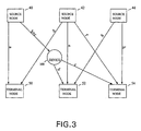
- Figure 3 shows an interconnect fabric that results from the first pass through step 24.
- a flow-set having an interconnect device 160, a flow of b, and a flow of c is the result of the merger of the flow-set having the flow of b and the flow-set having the flow of c.
- the interconnect fabric has a port violation of one at the source node 42 and a port violation of one at each of the terminal nodes 52 and 54.
- the next pass through step 24 results in the selection and merger of the flow-set corresponding to the interconnect device 160 with the flow-set having the flow of e which will alleviate the port violation of the terminal node 52.
- Figure 4 shows an interconnect fabric that results from the second pass through step 24.
- the flow-set corresponding to the interconnect device 160 now carries the flow of e in addition to the flows of b and c.
- the interconnect fabric has a port violation of one at the source node 42 and a port violation of one at the terminal node 54.
- the next pass through step 24 results in the selection and merger of the flow-set having the flow of f with the flow-set corresponding to the interconnect device 160 which will alleviate the port violation of the source node 42 as well as the port violation of the terminal node 54.
- Figure 5 shows an interconnect fabric that results from the third pass through step 24.
- the flow-set corresponding to the interconnect device 160 now carries the flow of f as well as the flows b, c, and e.
- the interconnect fabric has no port violation remaining.
- a cost saving may be obtained by merging the flow-set having the flow of a into the flow-set corresponding to the interconnect device 160. That merger would obviate the need for a communication link between the source node 40 and the terminal node 50, replacing that link with one between the interconnect node 160 and the terminal node 50, and thereby saving the costs associated with a port on the source node 40 in exchange for the lower costs, in this example, of a port on the interconnect node 160.
- Figure 6 shows an interconnect fabric that results from merging the flow-set having the flow of a into the flow-set corresponding to the interconnect device 160.
- the flow-set corresponding to the interconnect device 160 now includes the flow a in addition to the flows of b, c, e, and f.
- the interconnect fabric has no port violation remaining and no remaining opportunities for cost saving.
- Each flow-set has at most one interconnect device associated with it and all of the flows for the flow-set are routed through that interconnect device or a single communication link if possible.
- their existing interconnect devices, if any, are replaced by a single interconnect device which may be of a different type than the replaced interconnect devices.
- the interconnect device that results in the least expensive routing of the flows in the flow-set is chosen from among those interconnect devices that are feasible for the flow-set.
- Figure 7 shows a system having a fabric design tool 100 that employs the method 200 to generate an interconnect fabric design 120 in response to a set of design information 130.
- the fabric design tool 100 may be implemented in software.
- the design information 130 in one embodiment includes a set of flow requirements data 110, a set of port availability data 112, a set of bandwidth data 114, and a set of cost data 116.
- the design information may be implemented as an information store such as a file or set of files, a database or databases, etc.
- the flow requirements data 110 specifies the desired flow requirements for the interconnect fabric design 120.
- the desired flow requirements include a list of source nodes, a list of terminal nodes and one or more bandwidth requirements for each pairing of the source and terminal nodes.
- the port availability data 112 specifies the number of communication ports available on each source node and each terminal node and each available interconnect device.
- the available component data 114 specifies a list of available communication links that may be employed in the interconnect fabric design 120 and specifies the bandwidth provided by each and any other relevant constraints. There are numerous examples of available communication links including fiber optic links, fibre channel links, wire-based links, and links such as SCSI as well as wireless links. The available component data 114 also specifies a list of available interconnect devices such as switching hubs, repeaters, etc., and port bandwidth, device bandwidth, and other relevant information.
- the cost data 116 specifies costs associated with the available communication links and interconnect devices that may be employed in the interconnect fabric design 120.
- the cost data 116 also specifies the costs of ports for source and terminal nodes and interconnect devices. Other relevant costs may also be indicated.
- the interconnect fabric design 120 generated by the fabric design tool 100 includes a list of the physical communication links and interconnect devices and ports, etc. and may include cost data.
Landscapes
- Engineering & Computer Science (AREA)
- Computer Networks & Wireless Communication (AREA)
- Signal Processing (AREA)
- Data Exchanges In Wide-Area Networks (AREA)
- Structure Of Telephone Exchanges (AREA)
Abstract
Description
| Terminal Node 50 | Terminal Node 52 | Terminal Node 54 | |
| Source Node 40 | a | b | c |
| Source Node 42 | d | e | f |
| Source | -- | g | h |
Claims (10)
- A method for designing an interconnect fabric for communication between a set of source nodes (40-44) and a set of terminal nodes (50-54), comprising the steps of:generating an arrangement of flow-sets in the interconnect fabric in response to a set of flow requirements for the source and terminal nodes;determining one or more port violations in the source and terminal nodes which are associated with the arrangement of flow-sets;alleviating at least one of the port violations by merging a pair of the flow-sets.
- The method of claim 1, wherein for each source and terminal node the step of determining one or more port violations comprises the step of determining a number by which a set of ports for the corresponding flow-sets exceed a set of available ports.
- The method of claim 2, wherein the step of alleviating at least one of the port violations comprises the step of alleviating at least one port violation of the source or terminal node for which the number is highest.
- The method of claim 2, wherein the step of alleviating at least one of the port violations comprises the step of alleviating at least one port violation of the source or terminal node for which the number is highest and for which the step of merging also alleviates the source or terminal node for which the number is next highest.
- The method of claim 2, wherein the step of alleviating at least one of the port violations comprises the step of alleviating at least one port violation of the source or terminal node for which the number is highest and for which the step of merging imposes a least cost.
- A system for designing an interconnect fabric for communication between a set of source nodes (40-44) and a set of terminal nodes (50-54), comprising:a set of design information (130) including a set of flow requirements for the interconnect fabric;fabric design tool (100) that generates a design for the interconnect fabric in response to the design information (130) by generating an arrangement of flow-sets in response to the flow requirements and determining one or more port violations in the source and terminal nodes which are associated with the arrangement of flow-sets and alleviating at least one of the port violations by merging a pair of the flow-sets.
- The system of claim 6, wherein the fabric design tool (100) determines the port violations for each source and terminal node by determining a number by which a set of ports for the corresponding flow-sets exceed a set of available ports.
- The system of claim 7, wherein the fabric design tool (100) alleviates at least one port violation of the source or terminal node for which the number is highest.
- The system of claim 7, wherein the fabric design tool (100) alleviates at least one port violation of the source or terminal node for which the number is highest and for which the merger also alleviates the source or terminal node for which the number is next highest.
- The system of claim 7, wherein the fabric design tool (100) alleviates at least one port violation of the source or terminal node for which the number is highest and for which the merger imposes a least cost.
Applications Claiming Priority (2)
| Application Number | Priority Date | Filing Date | Title |
|---|---|---|---|
| US707227 | 2000-11-06 | ||
| US09/707,227 US7000011B1 (en) | 2000-11-06 | 2000-11-06 | Designing interconnect fabrics |
Publications (2)
| Publication Number | Publication Date |
|---|---|
| EP1204251A2 true EP1204251A2 (en) | 2002-05-08 |
| EP1204251A3 EP1204251A3 (en) | 2003-08-13 |
Family
ID=24840857
Family Applications (1)
| Application Number | Title | Priority Date | Filing Date |
|---|---|---|---|
| EP01309079A Withdrawn EP1204251A3 (en) | 2000-11-06 | 2001-10-25 | Designing interconnect fabrics of networks |
Country Status (3)
| Country | Link |
|---|---|
| US (4) | US7000011B1 (en) |
| EP (1) | EP1204251A3 (en) |
| JP (1) | JP2002199005A (en) |
Families Citing this family (47)
| Publication number | Priority date | Publication date | Assignee | Title |
|---|---|---|---|---|
| US7000011B1 (en) * | 2000-11-06 | 2006-02-14 | Hewlett-Packard Development Company, Lp. | Designing interconnect fabrics |
| US7502839B2 (en) * | 2001-09-28 | 2009-03-10 | Hewlett-Packard Development Company, L.P. | Module-building method for designing interconnect fabrics |
| KR20030064244A (en) * | 2002-01-24 | 2003-07-31 | 고성민 | Auction method for real-time displaying bid ranking |
| US20030145294A1 (en) * | 2002-01-25 | 2003-07-31 | Ward Julie Ann | Verifying interconnect fabric designs |
| US9009004B2 (en) * | 2002-01-31 | 2015-04-14 | Hewlett-Packasrd Development Comany, L.P. | Generating interconnect fabric requirements |
| US20050015511A1 (en) * | 2003-07-02 | 2005-01-20 | Nec Laboratories America, Inc. | Accelerated large data distribution in overlay networks |
| US20050265359A1 (en) * | 2004-05-13 | 2005-12-01 | Drew Julie W | Optimizing switch port assignments |
| US7986639B1 (en) * | 2004-10-26 | 2011-07-26 | Sprint Communications Company L.P. | Topology management of a communications network |
| US7386585B2 (en) * | 2004-10-30 | 2008-06-10 | International Business Machines Corporation | Systems and methods for storage area network design |
| US8533016B1 (en) | 2005-01-30 | 2013-09-10 | Hewlett-Packard Development Company, L.P. | System and method for selecting a portfolio |
| JP5831264B2 (en) * | 2012-02-02 | 2015-12-09 | 富士通株式会社 | Information processing system, information processing apparatus, and program |
| US8464196B1 (en) * | 2012-03-28 | 2013-06-11 | Cadence Design Systems, Inc. | Method and system for routing optimally between terminals through intermediate vias in a circuit design |
| US8885510B2 (en) | 2012-10-09 | 2014-11-11 | Netspeed Systems | Heterogeneous channel capacities in an interconnect |
| US9330055B2 (en) * | 2013-06-04 | 2016-05-03 | International Business Machines Corporation | Modular architecture for extreme-scale distributed processing applications |
| US9471726B2 (en) | 2013-07-25 | 2016-10-18 | Netspeed Systems | System level simulation in network on chip architecture |
| US9054977B2 (en) * | 2013-08-05 | 2015-06-09 | Netspeed Systems | Automatic NoC topology generation |
| US9473388B2 (en) | 2013-08-07 | 2016-10-18 | Netspeed Systems | Supporting multicast in NOC interconnect |
| US9699079B2 (en) | 2013-12-30 | 2017-07-04 | Netspeed Systems | Streaming bridge design with host interfaces and network on chip (NoC) layers |
| US9473415B2 (en) | 2014-02-20 | 2016-10-18 | Netspeed Systems | QoS in a system with end-to-end flow control and QoS aware buffer allocation |
| US9537743B2 (en) * | 2014-04-25 | 2017-01-03 | International Business Machines Corporation | Maximizing storage controller bandwidth utilization in heterogeneous storage area networks |
| US9742630B2 (en) | 2014-09-22 | 2017-08-22 | Netspeed Systems | Configurable router for a network on chip (NoC) |
| US9571341B1 (en) | 2014-10-01 | 2017-02-14 | Netspeed Systems | Clock gating for system-on-chip elements |
| US9529400B1 (en) | 2014-10-29 | 2016-12-27 | Netspeed Systems | Automatic power domain and voltage domain assignment to system-on-chip agents and network-on-chip elements |
| US9660942B2 (en) | 2015-02-03 | 2017-05-23 | Netspeed Systems | Automatic buffer sizing for optimal network-on-chip design |
| US9444702B1 (en) | 2015-02-06 | 2016-09-13 | Netspeed Systems | System and method for visualization of NoC performance based on simulation output |
| US9568970B1 (en) | 2015-02-12 | 2017-02-14 | Netspeed Systems, Inc. | Hardware and software enabled implementation of power profile management instructions in system on chip |
| US9928204B2 (en) | 2015-02-12 | 2018-03-27 | Netspeed Systems, Inc. | Transaction expansion for NoC simulation and NoC design |
| US10348563B2 (en) | 2015-02-18 | 2019-07-09 | Netspeed Systems, Inc. | System-on-chip (SoC) optimization through transformation and generation of a network-on-chip (NoC) topology |
| US10050843B2 (en) | 2015-02-18 | 2018-08-14 | Netspeed Systems | Generation of network-on-chip layout based on user specified topological constraints |
| US9825809B2 (en) | 2015-05-29 | 2017-11-21 | Netspeed Systems | Dynamically configuring store-and-forward channels and cut-through channels in a network-on-chip |
| US9864728B2 (en) | 2015-05-29 | 2018-01-09 | Netspeed Systems, Inc. | Automatic generation of physically aware aggregation/distribution networks |
| US10218580B2 (en) | 2015-06-18 | 2019-02-26 | Netspeed Systems | Generating physically aware network-on-chip design from a physical system-on-chip specification |
| US10699186B2 (en) | 2015-12-02 | 2020-06-30 | Google Llc | Determining orders of execution of a neural network |
| US10452124B2 (en) | 2016-09-12 | 2019-10-22 | Netspeed Systems, Inc. | Systems and methods for facilitating low power on a network-on-chip |
| US11507487B2 (en) * | 2016-09-28 | 2022-11-22 | Vmware, Inc. | Control of a computing system to perform network fabric benchmark measurements |
| US20180159786A1 (en) | 2016-12-02 | 2018-06-07 | Netspeed Systems, Inc. | Interface virtualization and fast path for network on chip |
| US10313269B2 (en) | 2016-12-26 | 2019-06-04 | Netspeed Systems, Inc. | System and method for network on chip construction through machine learning |
| US10063496B2 (en) | 2017-01-10 | 2018-08-28 | Netspeed Systems Inc. | Buffer sizing of a NoC through machine learning |
| US10084725B2 (en) | 2017-01-11 | 2018-09-25 | Netspeed Systems, Inc. | Extracting features from a NoC for machine learning construction |
| US10469337B2 (en) | 2017-02-01 | 2019-11-05 | Netspeed Systems, Inc. | Cost management against requirements for the generation of a NoC |
| US10298485B2 (en) | 2017-02-06 | 2019-05-21 | Netspeed Systems, Inc. | Systems and methods for NoC construction |
| US10547514B2 (en) | 2018-02-22 | 2020-01-28 | Netspeed Systems, Inc. | Automatic crossbar generation and router connections for network-on-chip (NOC) topology generation |
| US10896476B2 (en) | 2018-02-22 | 2021-01-19 | Netspeed Systems, Inc. | Repository of integration description of hardware intellectual property for NoC construction and SoC integration |
| US10983910B2 (en) | 2018-02-22 | 2021-04-20 | Netspeed Systems, Inc. | Bandwidth weighting mechanism based network-on-chip (NoC) configuration |
| US11144457B2 (en) | 2018-02-22 | 2021-10-12 | Netspeed Systems, Inc. | Enhanced page locality in network-on-chip (NoC) architectures |
| US11176302B2 (en) | 2018-02-23 | 2021-11-16 | Netspeed Systems, Inc. | System on chip (SoC) builder |
| US11023377B2 (en) | 2018-02-23 | 2021-06-01 | Netspeed Systems, Inc. | Application mapping on hardened network-on-chip (NoC) of field-programmable gate array (FPGA) |
Family Cites Families (103)
| Publication number | Priority date | Publication date | Assignee | Title |
|---|---|---|---|---|
| US3806657A (en) * | 1972-12-26 | 1974-04-23 | Bell Telephone Labor Inc | Merging time slot interchanger for time division switching networks |
| DE3001638A1 (en) * | 1980-01-17 | 1981-07-23 | Siemens AG, 1000 Berlin und 8000 München | PASSIVE BUS SYSTEM FOR DECENTRALLY STRUCTURED MULTIPLE COMPUTER ARRANGEMENTS, IN PARTICULAR MULTIMICRO COMPUTER ARRANGEMENTS |
| US5113496A (en) | 1987-08-04 | 1992-05-12 | Mccalley Karl W | Bus interconnection structure with redundancy linking plurality of groups of processors, with servers for each group mounted on chassis |
| US4920487A (en) * | 1988-12-12 | 1990-04-24 | The United States Of America As Represented By The Administrator Of The National Aeronautics And Space Administration | Method of up-front load balancing for local memory parallel processors |
| DE69025852T2 (en) * | 1989-10-23 | 1996-08-29 | At & T Corp | Arrangement for the control of a digital branch switch from a switching system |
| US5107489A (en) | 1989-10-30 | 1992-04-21 | Brown Paul J | Switch and its protocol for making dynamic connections |
| US5426674A (en) * | 1990-02-06 | 1995-06-20 | Nemirovsky; Paul | Method and computer system for selecting and evaluating data routes and arranging a distributed data communication network |
| US5245609A (en) * | 1991-01-30 | 1993-09-14 | International Business Machines Corporation | Communication network and a method of regulating the transmission of data packets in a communication network |
| US5321813A (en) * | 1991-05-01 | 1994-06-14 | Teradata Corporation | Reconfigurable, fault tolerant, multistage interconnect network and protocol |
| US6275864B1 (en) * | 1991-08-13 | 2001-08-14 | Storage Technology Corporation | Matrix switch for a network management system |
| US5307449A (en) | 1991-12-20 | 1994-04-26 | Apple Computer, Inc. | Method and apparatus for simultaneously rendering multiple scanlines |
| US5524212A (en) | 1992-04-27 | 1996-06-04 | University Of Washington | Multiprocessor system with write generate method for updating cache |
| CA2094410C (en) * | 1992-06-18 | 1998-05-05 | Joshua Seth Auerbach | Distributed management communications network |
| US5329619A (en) * | 1992-10-30 | 1994-07-12 | Software Ag | Cooperative processing interface and communication broker for heterogeneous computing environments |
| GB2272312A (en) * | 1992-11-10 | 1994-05-11 | Ibm | Collaborative working in a network. |
| WO1995009395A1 (en) * | 1993-09-27 | 1995-04-06 | Oracle Corporation | Method and apparatus for parallel processing in a database system |
| US5598532A (en) * | 1993-10-21 | 1997-01-28 | Optimal Networks | Method and apparatus for optimizing computer networks |
| JP2770749B2 (en) * | 1993-12-28 | 1998-07-02 | 日本電気株式会社 | Multi-ring type failure recovery system |
| US5634004A (en) | 1994-05-16 | 1997-05-27 | Network Programs, Inc. | Directly programmable distribution element |
| JP3224963B2 (en) * | 1994-08-31 | 2001-11-05 | 株式会社東芝 | Network connection device and packet transfer method |
| US6314092B1 (en) | 1994-11-30 | 2001-11-06 | British Telecommunications Public Limited Company | Routing in a communications network |
| US5802286A (en) * | 1995-05-22 | 1998-09-01 | Bay Networks, Inc. | Method and apparatus for configuring a virtual network |
| US6807558B1 (en) * | 1995-06-12 | 2004-10-19 | Pointcast, Inc. | Utilization of information “push” technology |
| US5651005A (en) * | 1995-08-29 | 1997-07-22 | Microsoft Corporation | System and methods for supplying continuous media data over an ATM public network |
| US5835498A (en) * | 1995-10-05 | 1998-11-10 | Silicon Image, Inc. | System and method for sending multiple data signals over a serial link |
| US5805578A (en) * | 1995-10-27 | 1998-09-08 | International Business Machines Corporation | Automatic reconfiguration of multipoint communication channels |
| US5854903A (en) * | 1995-11-07 | 1998-12-29 | Lucent Technologies Inc. | Optimization method for routing and logical network design in multi-service networks |
| US6115747A (en) * | 1995-11-13 | 2000-09-05 | Roger E. Billings | Computer network interface that merges remote data received from other computers with local data before transmitting the merged data to a network |
| US6076117A (en) * | 1995-11-13 | 2000-06-13 | Billings; Roger E. | Packet merging hub system for sequentially merging received data in a network hub into data packets before broadcasting to a plurality of destination computers |
| US6003037A (en) * | 1995-11-14 | 1999-12-14 | Progress Software Corporation | Smart objects for development of object oriented software |
| US5793362A (en) * | 1995-12-04 | 1998-08-11 | Cabletron Systems, Inc. | Configurations tracking system using transition manager to evaluate votes to determine possible connections between ports in a communications network in accordance with transition tables |
| US5831610A (en) * | 1996-02-23 | 1998-11-03 | Netsuite Development L.P. | Designing networks |
| US5987517A (en) * | 1996-03-27 | 1999-11-16 | Microsoft Corporation | System having a library of protocol independent reentrant network interface functions for providing common calling interface for communication and application protocols |
| JP3697317B2 (en) * | 1996-05-28 | 2005-09-21 | 株式会社東芝 | Communication device |
| US5815402A (en) * | 1996-06-07 | 1998-09-29 | Micron Technology, Inc. | System and method for changing the connected behavior of a circuit design schematic |
| US5838919A (en) * | 1996-09-10 | 1998-11-17 | Ganymede Software, Inc. | Methods, systems and computer program products for endpoint pair based communications network performance testing |
| US6101170A (en) * | 1996-09-27 | 2000-08-08 | Cabletron Systems, Inc. | Secure fast packet switch having improved memory utilization |
| US6148000A (en) | 1996-10-02 | 2000-11-14 | International Business Machines Corporation | Merging of data cells at network nodes |
| US5831996A (en) * | 1996-10-10 | 1998-11-03 | Lucent Technologies Inc. | Digital circuit test generator |
| US6108782A (en) * | 1996-12-13 | 2000-08-22 | 3Com Corporation | Distributed remote monitoring (dRMON) for networks |
| US5878232A (en) * | 1996-12-27 | 1999-03-02 | Compaq Computer Corporation | Dynamic reconfiguration of network device's virtual LANs using the root identifiers and root ports determined by a spanning tree procedure |
| US6038219A (en) * | 1996-12-31 | 2000-03-14 | Paradyne Corporation | User-configurable frame relay network |
| US5978379A (en) * | 1997-01-23 | 1999-11-02 | Gadzoox Networks, Inc. | Fiber channel learning bridge, learning half bridge, and protocol |
| US6870847B2 (en) * | 1997-03-28 | 2005-03-22 | Cisco Technology, Inc. | Scheme for merging partially filled ATM cells |
| US6442584B1 (en) * | 1997-05-16 | 2002-08-27 | Sybase, Inc. | Methods for resource consolidation in a computing environment |
| US6088356A (en) * | 1997-06-30 | 2000-07-11 | Sun Microsystems, Inc. | System and method for a multi-layer network element |
| US6047199A (en) * | 1997-08-15 | 2000-04-04 | Bellsouth Intellectual Property Corporation | Systems and methods for transmitting mobile radio signals |
| JP3649367B2 (en) | 1997-09-26 | 2005-05-18 | ソニー株式会社 | Packet transmission control method and apparatus |
| US6052360A (en) * | 1997-10-23 | 2000-04-18 | Mci Communications Corporation | Network restoration plan regeneration responsive to transitory conditions likely to affect network traffic |
| US6272127B1 (en) * | 1997-11-10 | 2001-08-07 | Ehron Warpspeed Services, Inc. | Network for providing switched broadband multipoint/multimedia intercommunication |
| US5970232A (en) | 1997-11-17 | 1999-10-19 | Cray Research, Inc. | Router table lookup mechanism |
| JP3480801B2 (en) * | 1997-12-05 | 2003-12-22 | 株式会社東芝 | Packet transfer method and node device |
| US6078953A (en) * | 1997-12-29 | 2000-06-20 | Ukiah Software, Inc. | System and method for monitoring quality of service over network |
| US6247077B1 (en) * | 1998-02-06 | 2001-06-12 | Ncr Corporation | Highly-scalable parallel processing computer system architecture |
| US6031984A (en) | 1998-03-09 | 2000-02-29 | I2 Technologies, Inc. | Method and apparatus for optimizing constraint models |
| US6570850B1 (en) * | 1998-04-23 | 2003-05-27 | Giganet, Inc. | System and method for regulating message flow in a digital data network |
| US6169735B1 (en) * | 1998-04-30 | 2001-01-02 | Sbc Technology Resources, Inc. | ATM-based distributed virtual tandem switching system |
| US6212568B1 (en) * | 1998-05-06 | 2001-04-03 | Creare Inc. | Ring buffered network bus data management system |
| US6603769B1 (en) * | 1998-05-28 | 2003-08-05 | Cisco Technology, Inc. | Method and system for improving traffic operation in an internet environment |
| US6594701B1 (en) * | 1998-08-04 | 2003-07-15 | Microsoft Corporation | Credit-based methods and systems for controlling data flow between a sender and a receiver with reduced copying of data |
| US6557169B1 (en) * | 1998-10-11 | 2003-04-29 | International Business Machines Corporation | Method and system for changing the operating system of a workstation connected to a data transmission network |
| US6253339B1 (en) | 1998-10-28 | 2001-06-26 | Telefonaktiebolaget Lm Ericsson (Publ) | Alarm correlation in a large communications network |
| US6363334B1 (en) * | 1998-11-05 | 2002-03-26 | Lucent Technologies Inc. | Linear programming method of networking design for carrying traffic from endnodes to a core network at least cost |
| US6141355A (en) * | 1998-11-06 | 2000-10-31 | Path 1 Network Technologies, Inc. | Time-synchronized multi-layer network switch for providing quality of service guarantees in computer networks |
| US6366931B1 (en) | 1998-11-20 | 2002-04-02 | Hewlett-Packard Company | Apparatus for and method of non-linear constraint optimization in storage system configuration |
| US6611872B1 (en) * | 1999-01-11 | 2003-08-26 | Fastforward Networks, Inc. | Performing multicast communication in computer networks by using overlay routing |
| US6724757B1 (en) * | 1999-01-15 | 2004-04-20 | Cisco Technology, Inc. | Configurable network router |
| US6539027B1 (en) * | 1999-01-19 | 2003-03-25 | Coastcom | Reconfigurable, intelligent signal multiplexer and network design and maintenance system therefor |
| US6697854B1 (en) * | 1999-02-22 | 2004-02-24 | International Business Machines Corporation | Method and apparatus for providing configuration information using a SIGA vector and utilizing a queued direct input-output device |
| US6757731B1 (en) * | 1999-02-25 | 2004-06-29 | Nortel Networks Limited | Apparatus and method for interfacing multiple protocol stacks in a communication network |
| US6539531B2 (en) * | 1999-02-25 | 2003-03-25 | Formfactor, Inc. | Method of designing, fabricating, testing and interconnecting an IC to external circuit nodes |
| US6331905B1 (en) * | 1999-04-01 | 2001-12-18 | The Trustees Of Columbia University In The City Of New York | Network switch failure restoration |
| US6519632B1 (en) * | 1999-04-28 | 2003-02-11 | General Electric Company | Method and apparatus for configuring imaging system to communicate with multiple remote devices |
| US6701327B1 (en) * | 1999-05-11 | 2004-03-02 | 3Com Corporation | Merging network data sets comprising data acquired by interrogation of a network |
| US6631128B1 (en) * | 1999-05-27 | 2003-10-07 | Telefonaktiebolaget L M Ericcson (Publ) | Core network optimization of topology and technology for traffic handling |
| US6687222B1 (en) | 1999-07-02 | 2004-02-03 | Cisco Technology, Inc. | Backup service managers for providing reliable network services in a distributed environment |
| US6853970B1 (en) * | 1999-08-20 | 2005-02-08 | Hewlett-Packard Development Company, L.P. | Automatic design of processor datapaths |
| US6766381B1 (en) | 1999-08-27 | 2004-07-20 | International Business Machines Corporation | VLSI network processor and methods |
| US6633909B1 (en) * | 1999-09-23 | 2003-10-14 | International Business Machines Corporation | Notification method that guarantees a system manager discovers an SNMP agent |
| US6697369B1 (en) * | 1999-09-28 | 2004-02-24 | Lucent Technologies Inc | Admission control adjustment in data networks using maximum cell count |
| US6675328B1 (en) * | 1999-10-08 | 2004-01-06 | Vigilant Networks, Llc | System and method to determine data throughput in a communication network |
| US6625777B1 (en) * | 1999-10-19 | 2003-09-23 | Motorola, Inc. | Method of identifying an improved configuration for a communication system using coding gain and an apparatus therefor |
| US6628649B1 (en) * | 1999-10-29 | 2003-09-30 | Cisco Technology, Inc. | Apparatus and methods providing redundant routing in a switched network device |
| US6707794B1 (en) * | 1999-11-15 | 2004-03-16 | Networks Associates Technology, Inc. | Method, system and computer program product for physical link layer handshake protocol analysis |
| US6744767B1 (en) * | 1999-12-30 | 2004-06-01 | At&T Corp. | Method and apparatus for provisioning and monitoring internet protocol quality of service |
| US6697334B1 (en) | 2000-01-18 | 2004-02-24 | At&T Corp. | Method for designing a network |
| US6778496B1 (en) * | 2000-06-07 | 2004-08-17 | Lucent Technologies Inc. | Distributed call admission and load balancing method and apparatus for packet networks |
| US6668308B2 (en) * | 2000-06-10 | 2003-12-23 | Hewlett-Packard Development Company, L.P. | Scalable architecture based on single-chip multiprocessing |
| US6694361B1 (en) * | 2000-06-30 | 2004-02-17 | Intel Corporation | Assigning multiple LIDs to ports in a cluster |
| US6775230B1 (en) * | 2000-07-18 | 2004-08-10 | Hitachi, Ltd. | Apparatus and method for transmitting frames via a switch in a storage area network |
| US7000011B1 (en) * | 2000-11-06 | 2006-02-14 | Hewlett-Packard Development Company, Lp. | Designing interconnect fabrics |
| US6857027B1 (en) * | 2000-11-14 | 2005-02-15 | 3Com Corporation | Intelligent network topology and configuration verification using a method of loop detection |
| US6879564B2 (en) * | 2001-02-28 | 2005-04-12 | Microsoft Corp. | Method for designating communication paths in a network |
| US7099912B2 (en) * | 2001-04-24 | 2006-08-29 | Hitachi, Ltd. | Integrated service management system |
| US20020188732A1 (en) * | 2001-06-06 | 2002-12-12 | Buckman Charles R. | System and method for allocating bandwidth across a network |
| US6804245B2 (en) * | 2001-08-17 | 2004-10-12 | Mcdata Corporation | Compact, shared route lookup table for a fiber channel switch |
| US6526240B1 (en) * | 2001-08-28 | 2003-02-25 | Xerox Corporation | Versatile system for creating test images in a digital printing apparatus |
| US7502839B2 (en) | 2001-09-28 | 2009-03-10 | Hewlett-Packard Development Company, L.P. | Module-building method for designing interconnect fabrics |
| US20030145294A1 (en) * | 2002-01-25 | 2003-07-31 | Ward Julie Ann | Verifying interconnect fabric designs |
| US9009004B2 (en) * | 2002-01-31 | 2015-04-14 | Hewlett-Packasrd Development Comany, L.P. | Generating interconnect fabric requirements |
| US7277960B2 (en) * | 2003-07-25 | 2007-10-02 | Hewlett-Packard Development Company, L.P. | Incorporating constraints and preferences for determining placement of distributed application onto distributed resource infrastructure |
| US7426570B2 (en) * | 2003-07-25 | 2008-09-16 | Hewlett-Packard Development Company, L.P. | Determining placement of distributed application onto distributed resource infrastructure |
| US7191107B2 (en) * | 2003-07-25 | 2007-03-13 | Hewlett-Packard Development Company, L.P. | Method of determining value change for placement variable |
-
2000
- 2000-11-06 US US09/707,227 patent/US7000011B1/en not_active Expired - Fee Related
-
2001
- 2001-10-25 EP EP01309079A patent/EP1204251A3/en not_active Withdrawn
- 2001-11-05 JP JP2001339977A patent/JP2002199005A/en active Pending
- 2001-12-19 US US10/027,564 patent/US7076537B2/en not_active Expired - Fee Related
- 2001-12-19 US US10/027,589 patent/US7032013B2/en not_active Expired - Fee Related
-
2002
- 2002-01-17 US US10/052,682 patent/US7233983B2/en not_active Expired - Lifetime
Also Published As
| Publication number | Publication date |
|---|---|
| US7000011B1 (en) | 2006-02-14 |
| US7032013B2 (en) | 2006-04-18 |
| EP1204251A3 (en) | 2003-08-13 |
| JP2002199005A (en) | 2002-07-12 |
| US20020091845A1 (en) | 2002-07-11 |
| US20020091804A1 (en) | 2002-07-11 |
| US7076537B2 (en) | 2006-07-11 |
| US7233983B2 (en) | 2007-06-19 |
| US20020083159A1 (en) | 2002-06-27 |
Similar Documents
| Publication | Publication Date | Title |
|---|---|---|
| US7000011B1 (en) | Designing interconnect fabrics | |
| Labourdette et al. | Branch-exchange sequences for reconfiguration of lightwave networks | |
| US8327021B2 (en) | Technique of determining connectivity solutions for network elements | |
| US8345538B2 (en) | Apparatus and method for finding a pair of disjoint paths in a communication network | |
| EP0423053A2 (en) | Method of using cached partial trees in computing a path in a data communication network | |
| CA2245640C (en) | Network management system with network designing function | |
| US7414985B1 (en) | Link aggregation | |
| US7308494B1 (en) | Reprovisioning technique for an interconnect fabric design | |
| US7085242B2 (en) | Virtual IP topology reconfiguration migration | |
| EP1232605B1 (en) | Method and system for management of network domains | |
| US6301267B1 (en) | Smart switch | |
| US7106729B1 (en) | Switching control mechanism based upon the logical partitioning of a switch element | |
| Qin et al. | Orchid: enhancing HPC interconnection networks through infrequent topology reconfiguration | |
| Labourdette et al. | Reconfiguration algorithms for rearrangeable lightwave networks | |
| CN102325070A (en) | Service grooming method and device | |
| EP2285046A1 (en) | Method and apparatus for realizing interaction of optical channel data unit protection tangency rings | |
| Shi et al. | Interconnection of self-healing rings | |
| US8301026B2 (en) | Network restoration under dual failures using path protecting preconfigured cycles | |
| US20050108241A1 (en) | Method for designing low cost static networks | |
| US7039045B1 (en) | Passthrough switching control mechanism based upon the logical partitioning of a switch element | |
| KR100775691B1 (en) | How to set up mesh group in communication network | |
| KR101006804B1 (en) | How to manage soft-PCC information in ATM network management system | |
| Chen et al. | Rearrangeable nonblocking optical interconnection network fabrics with crosstalk constraints | |
| JP3042508B2 (en) | Routing device and routing method | |
| Lee et al. | Preserving survivability during logical topology reconfiguration in WDM ring networks |
Legal Events
| Date | Code | Title | Description |
|---|---|---|---|
| PUAI | Public reference made under article 153(3) epc to a published international application that has entered the european phase |
Free format text: ORIGINAL CODE: 0009012 |
|
| AK | Designated contracting states |
Kind code of ref document: A2 Designated state(s): AT BE CH CY DE DK ES FI FR GB GR IE IT LI LU MC NL PT SE TR |
|
| AX | Request for extension of the european patent |
Free format text: AL;LT;LV;MK;RO;SI |
|
| PUAL | Search report despatched |
Free format text: ORIGINAL CODE: 0009013 |
|
| RIC1 | Information provided on ipc code assigned before grant |
Ipc: 7H 04L 12/24 A |
|
| AK | Designated contracting states |
Designated state(s): AT BE CH CY DE DK ES FI FR GB GR IE IT LI LU MC NL PT SE TR |
|
| AX | Request for extension of the european patent |
Extension state: AL LT LV MK RO SI |
|
| AKX | Designation fees paid | ||
| REG | Reference to a national code |
Ref country code: DE Ref legal event code: 8566 |
|
| STAA | Information on the status of an ep patent application or granted ep patent |
Free format text: STATUS: THE APPLICATION IS DEEMED TO BE WITHDRAWN |
|
| 18D | Application deemed to be withdrawn |
Effective date: 20040214 |