EP1204223A1 - Repeater - Google Patents
Repeater Download PDFInfo
- Publication number
- EP1204223A1 EP1204223A1 EP00937322A EP00937322A EP1204223A1 EP 1204223 A1 EP1204223 A1 EP 1204223A1 EP 00937322 A EP00937322 A EP 00937322A EP 00937322 A EP00937322 A EP 00937322A EP 1204223 A1 EP1204223 A1 EP 1204223A1
- Authority
- EP
- European Patent Office
- Prior art keywords
- radio wave
- electric power
- composite
- signal
- reception antenna
- Prior art date
- Legal status (The legal status is an assumption and is not a legal conclusion. Google has not performed a legal analysis and makes no representation as to the accuracy of the status listed.)
- Granted
Links
Images
Classifications
-
- H—ELECTRICITY
- H04—ELECTRIC COMMUNICATION TECHNIQUE
- H04B—TRANSMISSION
- H04B7/00—Radio transmission systems, i.e. using radiation field
- H04B7/14—Relay systems
- H04B7/15—Active relay systems
- H04B7/155—Ground-based stations
- H04B7/15528—Control of operation parameters of a relay station to exploit the physical medium
- H04B7/15535—Control of relay amplifier gain
Definitions
- the present invention relates to a relay device used for terrestrial broadcasting in which both a reception frequency and a transmission frequency having the same value as each other are used.
- a relay device In a terrestrial television broadcasting system, a relay device is installed in a relay station to send out a broadcast radio wave to regions such as a mountainous region in which it is difficult to receive the broadcast radio wave.
- a broadcast radio wave transmitted from a parent station is received, amplified and again sent out.
- OFDM orthogonal frequency division multiplex
- a single frequency network SFN
- it is studied to prepare the SFN in the terrestrial digital broadcasting, and it is studied to use the reception frequency and the transmission frequency having the same value as each other in a relay device so as to efficiently use the frequency.
- both a radio wave transmitted from a parent station and a radio wave transmitted from the relay station are received in a reception antenna of the relay device. In this case, there is a possibility that a signal is oscillated in an amplifying unit of the relay device and a broadcast service cannot be performed.
- a received electric power D of the radio wave received in the parent station and a received electric power U of a transmission radio wave (or a go-around radio wave) of the relay station satisfy a condition D>U.
- the electric power of the radio wave transmitted from the relay device is sufficiently higher than the electric power of the radio wave received in the relay device, it is not generally easy that the condition D>U is satisfied. Therefore, various methods have been proposed to remove the go-around radio wave and to sufficiently reduce the received electric power U of the transmission radio wave of the relay station.
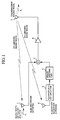
- FIG. 1 is a block diagram showing the configuration of a conventional relay device disclosed in Published Unexamined Japanese Patent Application No. H11-298421 (1999).
- Fig. 1 indicates a main reception antenna for receiving both a radio wave (of a frequency f 1 ) transmitted from a parent station and a go-around radio wave of a relay station in which the relay device is installed.
- 2 indicates a subsidiary reception antenna for receiving the go-around radio wave of the relay station.
- 3 indicates a changeable attenuator for changing an amplitude of a reception signal of the go-around radio wave received in the subsidiary reception antenna 2 by a preset attenuation factor.
- 4 indicates a phase shifting unit (or phase shifter) for changing a phase of a signal output from the changeable attenuator 3 by a preset shifting phase value.
- 5 indicates a composite signal producing unit (or composite signal producer) for producing a composite signal from both a signal of the radio wave of the parent station and a signal of the go-around radio wave received in the main reception antenna 1 and the signal sent from the phase shifting unit 4.
- 6 indicates an amplifying unit for amplifying the composite signal produced in the composite signal producing unit 5.
- 7 indicates a transmission antenna for transmitting a transmission radio wave (of the frequency f 1 ) of the relay station according to the composite signal amplified in the amplifying unit 6.
- the main reception antenna 1 has a directivity in the direction of the parent station, and the radio wave transmitted from the parent station is received in the main reception antenna 1. Also, a go-around radio wave transmitted from the transmission antenna 7 of the relay station is mixed with the radio wave of the parent station and is received in the main reception antenna 1. A reception signal composed of a mixture of the radio wave of the parent station and the go-around radio wave is received in the composite signal producing unit 5.
- the subsidiary reception antenna 2 is directed towards the transmission antenna 7, and the go-around radio wave transmitted from the transmission antenna 7 of the relay station is received in the subsidiary reception antenna 2.
- An amplitude of a reception signal of the go-around radio wave is changed by a preset attenuation factor in the changeable attenuator 3.
- a phase of a signal received in the phase shifting unit 4 is changed by a preset shifting phase value, and the signal is output to the composite signal producing unit 5.
- a composite signal is produced from a signal of a mixture of the radio wave of the parent station and the go-around radio wave received in the main reception antenna 1 and a signal of the go-around radio wave which is received in the subsidiary reception antenna 2 and of which the amplitude and the phase are adjusted.
- the attenuation factor of the changeable attenuator 3 and the shifting phase value of the phase shifting unit 4 are set so as to produce a composite signal from a signal of the go-around radio wave received in the main reception antenna 1 and a signal of the go-around radio wave received in the subsidiary reception antenna 2 having the same amplitude as each other at phases opposite to each other. Therefore, the signal of the go-around radio wave is canceled out in the composite signal, and the output of the composite signal producing unit 5 is composed of the composite signal of only the radio wave component of the parent station.
- the conventional relay device has the above-described configuration, when characteristics of the main reception antenna 1, the subsidiary reception antenna 2 and/or the transmission antenna 7 are changed due to a change of the environment caused by wind, snow or the like, the two go-around radio waves received in the composite signal producing unit 5 do not have the same amplitude as each other at the phases opposite to each other. Therefore, a problem has arisen that the go-around radio wave cannot be completely removed from the composite signal.
- the present invention is provided to solve the above-described problem, and the object of the present invention is to provide a relay device in which a go-around radio wave can be canceled out without the superposition of a relay station identification signal while being adapted for a change of the environment caused by wind or snow.
- a relay device in which a radio wave of a parent station is received and amplified and a transmission radio wave having the same frequency as that of the radio wave of the parent station is transmitted, comprises a main reception antenna for receiving both the radio wave of the parent station and a go-around radio wave of a relay station, a subsidiary reception antenna for receiving the go-around radio wave of the relay station, a changeable attenuator for changing an amplitude of a signal of the go-around radio wave received by the subsidiary reception antenna, a phase shifter for changing a phase of the signal of the go-around radio wave received by the subsidiary reception antenna, a composite signal producer for producing a composite signal from a signal of the radio wave of the parent station received by the main reception antenna, the signal of the go-around radio wave of the relay station and the signal of which the amplitude is changed by the changeable attenuator and the phase is changed by the phase shifter, a directivity coupler for extracting a composite voltage of the composite signal output from the composite signal producer, an electric
- the go-around radio wave can be cancelled while the relay device is adapted for a change of an environment of the relay device.
- the relay device further comprises an output controller for controlling an output of the transmission radio wave transmitted from the relay station according to an instruction of the microcomputer when the supply of an electric power is started.
- the oscillation occurring in the relay device can be suppressed when the supply of an electric power to the relay device is started.
- an initial operation point of the changeable attenuator and an initial operation point of the phase shifter are automatically detected by the microcomputer by obtaining a minimum value of the composite electric power obtained by the electric power detector.
- the relay device further comprises an output controller for controlling an output of the transmission radio wave transmitted from the relay station according to an instruction of the microcomputer when an initial operation point of the changeable attenuator and an initial operation point of the phase shifter are automatically detected by the microcomputer.
- the oscillation occurring in the relay device can be suppressed during the automatic detection of the initial operation points performed by the microcomputer.
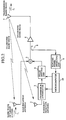
- Fig. 2 is a block diagram showing the configuration of a relay device according to a first embodiment of the present invention.
- 8 indicates a directivity coupling unit (or directivity coupler) for extracting a composite voltage of the composite signal output from the composite signal producing unit 5.
- 9 indicates an electric power detecting unit (or electric power detector) for obtaining a composite electric power from the composite voltage extracted in the directivity coupling unit 8.
- 10 indicates a microcomputer for controlling an attenuation factor of the changeable attenuator 3 and a shifting phase value of the phase shifting unit 4 so as to minimize an average value of the composite electric power obtained in the electric power detecting unit 9.
- the other constitutional elements are the same as or equivalent to those of the conventional relay device shown in Fig. 1.
- a composite voltage output from the composite signal producing unit 5 is extracted in the directivity coupling unit 8, a composite electric power is obtained in the electric power detecting unit 9 from the composite voltage extracted in the directivity coupling unit 8, and the composite electric power is input to the microcomputer 10.
- a voltage V M1 of a radio wave of a parent station received in the main reception antenna 1 is expressed according to an equation (1).
- V M1 V d f(t)
- a voltage V M2 of a go-around radio wave received in the main reception antenna 1 is expressed according to an equation (2).
- V M2 V U1 e j ⁇ 1 f(t - ⁇ t)
- V d denotes an average voltage of the radio wave of the parent station
- V U1 denotes an average voltage of the go-around radio wave received in the main reception antenna 1
- ⁇ 1 denotes a phase of the go-around radio wave received in the main reception antenna 1
- ⁇ t denotes a time period from the reception of the radio wave of the parent station to the reception of the go-around radio wave in the main reception antenna 1 or the subsidiary reception antenna 2 through the processing of the radio wave in the relay device and the transmission of the go-around radio wave from the transmission antenna 7.
- the time period ⁇ t is normally equal to or higher than 1 ⁇ s.
- V s2 V U2 e j ⁇ 2 f(t - ⁇ t)
- V U2 denotes an average voltage of the go-around radio wave received in the subsidiary reception antenna 2
- ⁇ 2 denotes a phase of the go-around radio wave received in the subsidiary reception antenna 2.
- V 0 2 V d 2 f 2 (t) + (V U1 e j ⁇ 1 + ⁇ V U2 e j( ⁇ 2+ ⁇ ) ) 2 f 2 (t - ⁇ t) + 2 V d (V U1 e j ⁇ 1 + ⁇ V U2 e j( ⁇ 2+ ⁇ ) ) f(t) f(t - ⁇ t)
- V d V U1 e j ⁇ 1 + ⁇ V U2 e j( ⁇ 2+ ⁇ )
- f(t) f(t - ⁇ t) an average of f(t) f(t - ⁇ t) is equal to 0 due to the characteristics of the OFDM method of the terrestrial digital broadcasting.
- the attenuation factor ⁇ of the changeable attenuator 3 is set according to an equation (8).
- the shifting phase value ⁇ of the phase shifting unit 4 is set according to an equation (9).
- the second term of the equation (7) is equal to 0. Therefore, it is realized that the go-around radio wave is canceled out in the composite voltage output from the composite signal producing unit 5.
- the relay device is set to a state of the canceling-out of the go-around radio wave.
- the attenuation factor of the changeable attenuator 3 and a degree of phase shifted in the phase shifting unit 4 are controlled by the microcomputer 10 so as to minimize the average value
- the relay device on the assumption that initial operation points of both the changeable attenuator 3 and the phase shifting unit 4 are set when the relay device is installed in the relay station, the relay device is operated while being adapted for a change of the environment. However, it is possible to automatically obtain the initial operation points.
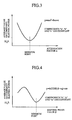
- Fig. 3 is a view showing a characteristic of a change of the average value
- of the composite electric power with respect to the attenuation factor ⁇ of the changeable attenuator 3 is expressed by a quadratic curve, and an operation point corresponding to the canceling-out of the go-around radio wave is placed at a point of Fig. 3 at which the average value
- Fig. 4 is a view showing a characteristic of a change of the average value
- of the composite electric power with respect to the shifting phase value ⁇ is expressed by a cosine curve, and an operation point corresponding to the canceling-out of the go-around radio wave is placed at a point of Fig. 4 at which the average value
- the initial operation point at which the average value
- the initial operation points of both the changeable attenuator 3 and the phase shifting unit 4 are measured and set.
- the go-around radio wave cannot be sufficiently canceled out due to measurement errors of the initial operation points. Therefore, there is a probability that a signal oscillation occurs in the relay device.
- the initial operation points of both the changeable attenuator 3 and the phase shifting unit 4 are automatically detected by the microcomputer 10.
- the go-around radio wave cannot be sufficiently canceled out during the detection of the initial operation points. Therefore, in the same manner, there is a probability that a signal oscillation occurs in the relay device.
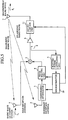
- Fig. 5 is a block diagram showing the configuration of a relay device according to a third embodiment of the present invention.
- 11 indicates an output control unit (or output controller) for controlling an output of the amplifying unit 6 by using the microcomputer 10 and outputting the output of the amplifying unit 6 to the transmission antenna 7.
- an output of the output control unit 11 is set to zero under the control of the microcomputer 10 to control the relay device not to output a transmission radio wave from the relay device.
- an output value of the electric power detecting unit 9 is stored in the microcomputer 10. Because no go-around radio wave is included in this output value of the electric power detecting unit 9, the output value indicates a reception level of the radio wave of the parent station.
- the output control unit 11 is controlled by the microcomputer 10 so as to heighten an output level (or output value) of the relay device little by little until the output level of the relay device reaches a regular output level. Therefore, a signal oscillation occurring in the relay device can be avoided.
- a threshold value is preset to a value ranging from the output value stored in the microcomputer 10 to the double of the output value.
- an electric power detected in the electric power detecting unit 9 is equal to or higher than the preset threshold value, operation points set in both the changeable attenuator 3 and the phase shifting unit 4 differ from optimum operation points at which the average value
- an output of the relay device is fixed at the operation points under the control of the output control unit 11, the optimum operation points are detected in the same manner as in the case of the change of the environment, and the output of the relay device is gradually heightened.
- the output level of the output control unit 11 is fixed to an appropriate level, which is equal to or lower than half of the regular output level, according to an instruction sent from the microcomputer 10. In this case, because an oscillation condition for the relay device is not satisfied, a signal oscillation occurring in the relay device can be avoided.
- an output level of the relay device is controlled by the output control unit 11 according to the control of the microcomputer 10. Therefore, when the supply of an electric power to the relay device is started or initial operation points are automatically detected by the microcomputer 10, the oscillation occurring in the relay device can be suppressed.
- a transmission radio wave having the same frequency as that of a radio wave received from a parent station is transmitted. Therefore, the relay device is appropriate to the canceling-out of a go-around radio wave while being adapted for a change of an environment of the relay device caused by wind or snow.
Landscapes
- Engineering & Computer Science (AREA)
- Computer Networks & Wireless Communication (AREA)
- Signal Processing (AREA)
- Radio Relay Systems (AREA)
- Noise Elimination (AREA)
Abstract
Description
Claims (4)
- A relay device, in which a radio wave of a parent station is received and amplified and a transmission radio wave having the same frequency as that of the radio wave of the parent station is transmitted, comprising:a main reception antenna for receiving both the radio wave of the parent station and a go-around radio wave of a relay station;a subsidiary reception antenna for receiving the go-around radio wave of the relay station;a changeable attenuator for changing an amplitude of a signal of the go-around radio wave received by the subsidiary reception antenna;a phase shifter for changing a phase of the signal of the go-around radio wave received by the subsidiary reception antenna;a composite signal producer for producing a composite signal from a signal of the radio wave of the parent station received by the main reception antenna, the signal of the go-around radio wave of the relay station and the signal of which the amplitude is changed by the changeable attenuator and the phase is changed by the phase shifter;a directivity coupler for extracting a composite voltage of the composite signal output from the composite signal producer;an electric power detector for obtaining a composite electric power from the composite voltage extracted by the directivity coupler; anda microcomputer for controlling both a change of the amplitude performed by the changeable attenuator and a change of the phase performed by the phase shifter so as to minimize an average value of the composite electric power obtained by the electric power detector.
- A relay device according to claim 1, further comprising:an output controller for controlling an output of the transmission radio wave transmitted from the relay station according to an instruction of the microcomputer when the supply of an electric power is started.
- A relay device according to claim 1, wherein an initial operation point of the changeable attenuator and an initial operation point of the phase shifter are automatically detected by the microcomputer by obtaining a minimum value of the composite electric power obtained by the electric power detector.
- A relay device according to claim 1, further comprising:an output controller for controlling an output of the transmission radio wave transmitted from the relay station according to an instruction of the microcomputer when an initial operation point of the changeable attenuator and an initial operation point of the phase shifter are automatically detected by the microcomputer.
Applications Claiming Priority (1)
| Application Number | Priority Date | Filing Date | Title |
|---|---|---|---|
| PCT/JP2000/004018 WO2001099308A1 (en) | 2000-06-20 | 2000-06-20 | Repeater |
Publications (3)
| Publication Number | Publication Date |
|---|---|
| EP1204223A1 true EP1204223A1 (en) | 2002-05-08 |
| EP1204223A4 EP1204223A4 (en) | 2003-02-19 |
| EP1204223B1 EP1204223B1 (en) | 2007-02-28 |
Family
ID=11736164
Family Applications (1)
| Application Number | Title | Priority Date | Filing Date |
|---|---|---|---|
| EP00937322A Expired - Lifetime EP1204223B1 (en) | 2000-06-20 | 2000-06-20 | Repeater |
Country Status (5)
| Country | Link |
|---|---|
| US (1) | US6888881B1 (en) |
| EP (1) | EP1204223B1 (en) |
| JP (1) | JP3989831B2 (en) |
| DE (1) | DE60033666D1 (en) |
| WO (1) | WO2001099308A1 (en) |
Families Citing this family (18)
| Publication number | Priority date | Publication date | Assignee | Title |
|---|---|---|---|---|
| DE60322541D1 (en) * | 2002-06-21 | 2008-09-11 | Qualcomm Inc | INTERMEDIATE AMPLIFIERS FOR WIRELESS LOCAL NETWORKS |
| US8885688B2 (en) | 2002-10-01 | 2014-11-11 | Qualcomm Incorporated | Control message management in physical layer repeater |
| AU2003274992A1 (en) * | 2002-10-11 | 2004-05-04 | Widefi, Inc. | Reducing loop effects in a wireless local area network repeater |
| US8078100B2 (en) * | 2002-10-15 | 2011-12-13 | Qualcomm Incorporated | Physical layer repeater with discrete time filter for all-digital detection and delay generation |
| KR20050071571A (en) * | 2002-10-15 | 2005-07-07 | 위데피, 인코포레이티드 | Wireless local area network repeater with automatic gain control for extending network coverage |
| US7230935B2 (en) * | 2002-10-24 | 2007-06-12 | Widefi, Inc. | Physical layer repeater with selective use of higher layer functions based on network operating conditions |
| EP1568167A4 (en) * | 2002-11-15 | 2010-06-16 | Qualcomm Inc | Wireless local area network repeater with detection |
| US8027642B2 (en) * | 2004-04-06 | 2011-09-27 | Qualcomm Incorporated | Transmission canceller for wireless local area network |
| KR101291850B1 (en) | 2004-05-13 | 2013-07-31 | 퀄컴 인코포레이티드 | Non-frequency translating repeater with downlink detection for uplink and downlink synchronization |
| US7187904B2 (en) | 2004-06-03 | 2007-03-06 | Widefi, Inc. | Frequency translating repeater with low cost high performance local oscillator architecture |
| JP4524148B2 (en) * | 2004-07-16 | 2010-08-11 | 株式会社日立国際電気 | Wireless relay device |
| US8059727B2 (en) | 2005-01-28 | 2011-11-15 | Qualcomm Incorporated | Physical layer repeater configuration for increasing MIMO performance |
| JP5107997B2 (en) * | 2006-03-31 | 2012-12-26 | クゥアルコム・インコーポレイテッド | Enhanced physical layer repeater for operation within the WiMAX system |
| BRPI0715908A2 (en) * | 2006-09-01 | 2014-03-18 | Qualcomm Inc | REPEATER WITH A RECEIVER ANTENNA AND DUAL TRANSMITTER CONFIGURATION WITH ADJUSTMENT FOR MORE INSULATION |
| JP5199261B2 (en) | 2006-09-21 | 2013-05-15 | クゥアルコム・インコーポレイテッド | Method and apparatus for mitigating vibration between repeaters |
| KR20090074812A (en) * | 2006-10-26 | 2009-07-07 | 퀄컴 인코포레이티드 | Repeater technology for multiple input multiple output using beam former |
| JP2010226655A (en) * | 2009-03-25 | 2010-10-07 | Fujitsu Ltd | Relay method and relay device |
| JP7113438B2 (en) * | 2020-09-18 | 2022-08-05 | 日本通信機株式会社 | FM repeater |
Family Cites Families (3)
| Publication number | Priority date | Publication date | Assignee | Title |
|---|---|---|---|---|
| CA1235751A (en) * | 1985-01-09 | 1988-04-26 | Junji Namiki | One frequency repeater for a digital microwave radio system with cancellation of transmitter-to-receiver interference |
| DE69635606T2 (en) | 1995-10-26 | 2006-07-27 | Ntt Mobile Communications Network Inc. | RELAY STATION |
| JPH11298421A (en) | 1998-04-13 | 1999-10-29 | Nippon Hoso Kyokai <Nhk> | Synchronous repeater |
-
2000
- 2000-06-20 JP JP2002504046A patent/JP3989831B2/en not_active Expired - Fee Related
- 2000-06-20 EP EP00937322A patent/EP1204223B1/en not_active Expired - Lifetime
- 2000-06-20 US US10/049,906 patent/US6888881B1/en not_active Expired - Fee Related
- 2000-06-20 DE DE60033666T patent/DE60033666D1/en not_active Expired - Lifetime
- 2000-06-20 WO PCT/JP2000/004018 patent/WO2001099308A1/en not_active Ceased
Also Published As
| Publication number | Publication date |
|---|---|
| EP1204223A4 (en) | 2003-02-19 |
| DE60033666D1 (en) | 2007-04-12 |
| EP1204223B1 (en) | 2007-02-28 |
| WO2001099308A1 (en) | 2001-12-27 |
| US6888881B1 (en) | 2005-05-03 |
| JP3989831B2 (en) | 2007-10-10 |
Similar Documents
| Publication | Publication Date | Title |
|---|---|---|
| EP1204223A1 (en) | Repeater | |
| EP0227393B1 (en) | Radio repeater with spillover measurement | |
| KR100974194B1 (en) | Space Multiplexing Apparatus and Method for Backward Compatibility in Multiple Input / Output Wireless Communication Systems | |
| JPWO2001099308A1 (en) | relay device | |
| EP0689314B1 (en) | Frame synchronization in a device receiving digital radio transmissions | |
| EP0689308A1 (en) | A method for changing from one signal in a receiver of a digital broadcasting | |
| JP4452350B2 (en) | Digital television broadcast receiving apparatus and transmission / reception system | |
| JP3642213B2 (en) | Relay device | |
| EP1303002B1 (en) | Method and system for polarization alignment of an earth station antenna with the polarization axis of a satellite antenna | |
| JP3419750B2 (en) | Automatic repeater for mobile radio communication | |
| KR20040108468A (en) | Method and device for attaining synchronization from base station signals in time division duplex system | |
| JP4530833B2 (en) | Terrestrial digital broadcast signal level adjusting apparatus and television joint receiving method | |
| JP3117605B2 (en) | Synchronous broadcasting system | |
| JP3803278B2 (en) | Receiving unit for terrestrial digital broadcast retransmitter | |
| JP3025918B2 (en) | Program switching method | |
| JP4191920B2 (en) | Rounding interference measuring device | |
| JP4381902B2 (en) | Input field strength estimation circuit, method thereof, and receiver | |
| EP3987693B1 (en) | Apparatus for receiving and transmitting data via a satellite using at least two polarisations | |
| KR100651835B1 (en) | Control device and method used for digital multimedia broadcasting receiver and receiver | |
| JP2500781B2 (en) | Line switching device | |
| JP2008199219A (en) | Broadcast wave relay device and broadcast wave relay device monitoring system | |
| US8351471B2 (en) | Satellite communications system having transmitting station diversity | |
| JP2987077B2 (en) | Synchronous relay method and apparatus for FM broadcast | |
| US20110111722A1 (en) | Identification signal analyzing apparatus and method for compensating for separation and attenuation of channel profile | |
| KR20050027439A (en) | Repeater for digital satellite broadcasting |
Legal Events
| Date | Code | Title | Description |
|---|---|---|---|
| PUAI | Public reference made under article 153(3) epc to a published international application that has entered the european phase |
Free format text: ORIGINAL CODE: 0009012 |
|
| 17P | Request for examination filed |
Effective date: 20020220 |
|
| AK | Designated contracting states |
Kind code of ref document: A1 Designated state(s): AT BE CH CY DE DK ES FI FR GB GR IE IT LI LU MC NL PT SE |
|
| A4 | Supplementary search report drawn up and despatched |
Effective date: 20030108 |
|
| RIC1 | Information provided on ipc code assigned before grant |
Ipc: 7H 04B 7/155 B Ipc: 7H 04B 7/15 A |
|
| 17Q | First examination report despatched |
Effective date: 20030425 |
|
| RBV | Designated contracting states (corrected) |
Designated state(s): DE FR GB |
|
| RAP1 | Party data changed (applicant data changed or rights of an application transferred) |
Owner name: MITSUBISHI DENKI KABUSHIKI KAISHA |
|
| GRAP | Despatch of communication of intention to grant a patent |
Free format text: ORIGINAL CODE: EPIDOSNIGR1 |
|
| GRAS | Grant fee paid |
Free format text: ORIGINAL CODE: EPIDOSNIGR3 |
|
| GRAA | (expected) grant |
Free format text: ORIGINAL CODE: 0009210 |
|
| AK | Designated contracting states |
Kind code of ref document: B1 Designated state(s): DE FR GB |
|
| REG | Reference to a national code |
Ref country code: GB Ref legal event code: FG4D |
|
| REF | Corresponds to: |
Ref document number: 60033666 Country of ref document: DE Date of ref document: 20070412 Kind code of ref document: P |
|
| ET | Fr: translation filed | ||
| PGFP | Annual fee paid to national office [announced via postgrant information from national office to epo] |
Ref country code: DE Payment date: 20070827 Year of fee payment: 8 |
|
| PGFP | Annual fee paid to national office [announced via postgrant information from national office to epo] |
Ref country code: GB Payment date: 20070629 Year of fee payment: 8 |
|
| PLBE | No opposition filed within time limit |
Free format text: ORIGINAL CODE: 0009261 |
|
| STAA | Information on the status of an ep patent application or granted ep patent |
Free format text: STATUS: NO OPPOSITION FILED WITHIN TIME LIMIT |
|
| PG25 | Lapsed in a contracting state [announced via postgrant information from national office to epo] |
Ref country code: DE Free format text: LAPSE BECAUSE OF THE APPLICANT RENOUNCES Effective date: 20070920 |
|
| 26N | No opposition filed |
Effective date: 20071129 |
|
| PGFP | Annual fee paid to national office [announced via postgrant information from national office to epo] |
Ref country code: FR Payment date: 20070531 Year of fee payment: 8 |
|
| GBPC | Gb: european patent ceased through non-payment of renewal fee |
Effective date: 20080620 |
|
| REG | Reference to a national code |
Ref country code: FR Ref legal event code: ST Effective date: 20090228 |
|
| PG25 | Lapsed in a contracting state [announced via postgrant information from national office to epo] |
Ref country code: GB Free format text: LAPSE BECAUSE OF NON-PAYMENT OF DUE FEES Effective date: 20080620 |
|
| PG25 | Lapsed in a contracting state [announced via postgrant information from national office to epo] |
Ref country code: FR Free format text: LAPSE BECAUSE OF NON-PAYMENT OF DUE FEES Effective date: 20080630 |