EP1204216A1 - Method and apparatus for distortion compensation of radio device - Google Patents
Method and apparatus for distortion compensation of radio device Download PDFInfo
- Publication number
- EP1204216A1 EP1204216A1 EP99933123A EP99933123A EP1204216A1 EP 1204216 A1 EP1204216 A1 EP 1204216A1 EP 99933123 A EP99933123 A EP 99933123A EP 99933123 A EP99933123 A EP 99933123A EP 1204216 A1 EP1204216 A1 EP 1204216A1
- Authority
- EP
- European Patent Office
- Prior art keywords
- distortion compensation
- signal
- distortion
- compensation coefficient
- transmit signal
- Prior art date
- Legal status (The legal status is an assumption and is not a legal conclusion. Google has not performed a legal analysis and makes no representation as to the accuracy of the status listed.)
- Granted
Links
Images











Classifications
-
- H—ELECTRICITY
- H03—ELECTRONIC CIRCUITRY
- H03G—CONTROL OF AMPLIFICATION
- H03G5/00—Tone control or bandwidth control in amplifiers
- H03G5/16—Automatic control
- H03G5/165—Equalizers; Volume or gain control in limited frequency bands
-
- H—ELECTRICITY
- H03—ELECTRONIC CIRCUITRY
- H03F—AMPLIFIERS
- H03F1/00—Details of amplifiers with only discharge tubes, only semiconductor devices or only unspecified devices as amplifying elements
- H03F1/32—Modifications of amplifiers to reduce non-linear distortion
- H03F1/3241—Modifications of amplifiers to reduce non-linear distortion using predistortion circuits
- H03F1/3247—Modifications of amplifiers to reduce non-linear distortion using predistortion circuits using feedback acting on predistortion circuits
-
- H—ELECTRICITY
- H03—ELECTRONIC CIRCUITRY
- H03F—AMPLIFIERS
- H03F1/00—Details of amplifiers with only discharge tubes, only semiconductor devices or only unspecified devices as amplifying elements
- H03F1/32—Modifications of amplifiers to reduce non-linear distortion
- H03F1/3241—Modifications of amplifiers to reduce non-linear distortion using predistortion circuits
- H03F1/3258—Modifications of amplifiers to reduce non-linear distortion using predistortion circuits based on polynomial terms
-
- H—ELECTRICITY
- H03—ELECTRONIC CIRCUITRY
- H03F—AMPLIFIERS
- H03F1/00—Details of amplifiers with only discharge tubes, only semiconductor devices or only unspecified devices as amplifying elements
- H03F1/32—Modifications of amplifiers to reduce non-linear distortion
- H03F1/3241—Modifications of amplifiers to reduce non-linear distortion using predistortion circuits
- H03F1/3294—Acting on the real and imaginary components of the input signal
-
- H—ELECTRICITY
- H03—ELECTRONIC CIRCUITRY
- H03F—AMPLIFIERS
- H03F2201/00—Indexing scheme relating to details of amplifiers with only discharge tubes, only semiconductor devices or only unspecified devices as amplifying elements covered by H03F1/00
- H03F2201/32—Indexing scheme relating to modifications of amplifiers to reduce non-linear distortion
- H03F2201/3224—Predistortion being done for compensating memory effects
-
- H—ELECTRICITY
- H03—ELECTRONIC CIRCUITRY
- H03F—AMPLIFIERS
- H03F2201/00—Indexing scheme relating to details of amplifiers with only discharge tubes, only semiconductor devices or only unspecified devices as amplifying elements covered by H03F1/00
- H03F2201/32—Indexing scheme relating to modifications of amplifiers to reduce non-linear distortion
- H03F2201/3233—Adaptive predistortion using lookup table, e.g. memory, RAM, ROM, LUT, to generate the predistortion
Definitions
- This invention relates to a method and apparatus for compensating for distortion in a radio apparatus and, more particularly, to a distortion compensation method and distortion compensation apparatus for suppressing non-linear distortion of a transmission power amplifier in a radio apparatus and reducing leakage of power between adjacent channels.
- a vital technique is one which can suppress non-linear distortion by linearizing the amplitude characteristic of the power amplifier on the transmitting side and reduce the leakage of power between adjacent channels. Also essential is a technique which compensates for the occurrence of distortion that arises when an attempt is made to improve power efficiency by using an amplifier that exhibits poor linearity.
- Fig. 22 is a block diagram illustrating an example of a transmitting apparatus in a radio according to the prior art.
- a transmit-signal generator 1 transmits a serial digital data sequence and a serial/parallel (S/P) converter 2 divides the digital data sequence alternately one bit at a time to convert the data to two sequences, namely an in-phase component signal (also referred to as an "I signal”) and a quadrature component signal (also referred to as a "Q signal").
- a DA converter 3 converts the I and Q signals to respective analog baseband signals and inputs these to a quadrature modulator 4.
- the latter multiplies the input I and Q signals (the transmit baseband signals) by a reference carrier wave and a signal that has been phase-shifted relative to the reference carrier by 90° and sums the results of multiplication to thereby perform quadrature modulation and output the modulated signal.
- a frequency converter 5 mixes the quadrature-modulated signal and a local oscillation signal to thereby effect a frequency conversion, and a transmission power amplifier 6 power-amplifies the carrier output from the frequency converter 5.
- the amplified signal is released into the atmosphere from an antenna 7.
- the input/output characteristic [distortion function f(p)] of the transmission power amplifier is non-linear, as indicated by the dotted line in (a) of Fig. 23.
- Non-linear distortion arises as a result of non-linear characteristics, and the frequency spectrum in the vicinity of a transmission frequency f 0 develops side lobes, as shown in (b) of Fig. 23, leakage into the adjacent channel occurs and this causes interference between adjacent channels.
- the Cartesian-loop method and polar-loop method, etc. have been proposed as techniques for effecting distortion compensation by feedback and these methods are used to suppress the distortion of power amplifiers.
- Fig. 24 is a block diagram of a transmitting apparatus having a digital non-linear distortion compensating function that employs a DSP.
- a group of digital data (a modulation signal) sent from the transmit-signal generator 1 is converted to two signal sequences, namely I and Q signals, by the S/P converter 2, and these signals enter a predistorter 8 constituted by a DSP.
- a predistorter 8 constituted by a DSP.
- the distortion compensator 8 subjects the modulation signal to predistortion processing using the distortion compensation coefficient h(pi) that conforms to the level of the modulation signal, and inputs the processed signal to the DA converter 3.
- the latter converts the input I and Q signals to analog baseband signals and applies the baseband signals to the quadrature modulator 4.
- the latter multiplies the input I and Q signals by a reference carrier wave and a signal that has been phase-shifted relative to the reference carrier by 90°, respectively, and sums the results of multiplication to thereby perform quadrature modulation and output the modulated signal.
- the frequency converter 5 mixes the quadrature-modulated signal and a local oscillation signal to thereby effect a frequency conversion, and the transmission power amplifier 6 power-amplifies the carrier signal output from the frequency converter 5.
- the amplified signal is released into the atmosphere from the antenna 7.
- Part of the transmit signal is input to a frequency converter 10 via a directional coupler 9, whereby the signal undergoes a frequency conversion and is input to a quadrature detector 11.
- the latter performs quadrature detection by multiplying the input signal by a reference carrier wave and a signal that has been phase-shifted relative to the reference carrier by 90°, reproduces the I, Q signals of the baseband on the transmitting side and applies these signals to an AD converter 12.
- the latter converts the applied I and Q signals to digital data and inputs the digital data to a distortion compensator 8.
- the distortion compensator 8 compares the modulation signal with the demodulated obtained by demodulation in the quadrature detector 11 and proceeds to calculate and update the distortion compensation coefficient h(pi) in such a manner that the difference between the compared signals will become zero.
- the modulation signal to be transmitted next is then subjected to predistortion processing using the updated distortion compensation coefficient and the processed signal is output. By thenceforth repeating this operation, non-linear distortion of the transmission power amplifier 6 is suppressed to reduce the leakage of power between adjacent channels.
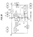
- Fig. 26 is a diagram useful in describing distortion compensation processing by an adaptive LMS.
- a multiplier which corresponds to the predistortion unit 8b in Fig. 25
- 15a multiplies the modulation signal (the input baseband signal) x(t) by a distortion compensation coefficient h n-1 (p).
- a transmission power amplifier 15b has a distortion function f(p).
- a distortion compensation coefficient memory (which corresponds to the distortion compensation coefficient memory 8a of Fig.
- 15e stores the distortion compensation coefficients that conform to the power levels of the modulation signal x(t).
- the memory 15e outputs the distortion compensation coefficient h n-1 (p) conforming to the power p of the modulation signal x(t) and updates the distortion compensation coefficient h n-1 (p) by a distortion compensation coefficient h n (p) found by the LMS algorithm.
- Reference characters 15f denote a complex-conjugate signal output unit 15f.
- a subtractor 15g outputs the difference e(t) between the modulation signal x(t) and the feedback demodulated signal y(t)
- a multiplier 15h performs multiplication between e(t) and u*(t)
- a multiplier 15i performs multiplication between h n-1 (p). and y*(t)
- a multiplier 15j performs multiplication by a step-size parameter ⁇
- an adder 15k adds h n-1 (p) and ⁇ e(t)u*(t).
- Reference characters 15m, 15n, 15p denote delay units.
- a delay time which is equivalent to the length of time from the moment the transmit signal x(t) enters to the moment the feedback (demodulated) signal y(t) is input to the subtractor 15g, is added onto the input signal.
- the units 15f ⁇ 15j construct a rotation calculation unit 16.
- a signal that has sustained distortion is indicated at u(t).
- the distortion compensation coefficient h(p) is updated so as to minimize the difference e(t) between the transmit signal x(t) and the feedback (demodulated) signal y(t), and the coefficient eventually converges to the optimum distortion compensation coefficient h(p) so that compensation is made for the distortion in the transmission power amplifier.
- the principle of digital non-linear distortion compensation is to feed back and detect a carrier obtained by quadrature modulation by a modulating signal, digitally convert and compare the amplitudes of the modulating signal (transmit baseband signal) and feedback signal (feedback baseband signal), and update the distortion compensation coefficient in real time based upon the comparison.
- a phenomenon occurs in which the actual transmission power amplifier generates unnecessary radiation power that differs between positive and negative frequency regions with respect to a center frequency f 0 . Further, frequency asymmetric distortion differs depending upon individual differences among devices. The reason for this phenomenon is that the distortion function of a transmission power amplifier depends not only upon the instantaneous value p of input power but also upon the value of input power in the past.
- an object of the present invention is to so arrange it that frequency asymmetric distortion can be compensated for so that a satisfactory distortion suppression effect can manifest itself.
- a further object of the present invention is eliminate a variance in the distortion compensation effect caused by individual differences among devices.
- distortion compensation coefficients for correcting distortion of a transmission power amplifier are stored in a memory, a distortion compensation coefficient conforming to a present transmit signal and a past transmit signal is read out of the memory, distortion compensation processing is applied to the transmit signal using this distortion compensation coefficient, the transmit signal to which distortion compensation processing has been applied is amplified and transmitted, and the distortion compensation coefficient is updated based upon the transmit signal before distortion compensation and an output signal from the transmission power amplifier.
- distortion compensation processing is executed upon reading one distortion compensation coefficient, which corresponds to a present transmit signal and a plurality of signals transmitted in the past, out of the memory.
- distortion compensation processing is executed upon reading a distortion compensation coefficient, which corresponds to a present transmit signal and a signal transmitted previously, out of the memory.
- distortion compensation processing is executed upon reading a distortion compensation coefficient, which corresponds to a present transmit signal and a difference between the present signal and a signal transmitted previously, out of the memory.
- distortion compensation processing is executed upon reading a distortion compensation coefficient, which corresponds to an instantaneous value of a present transmit signal and an envelope differential value, out of the memory.
- distortion compensation processing is executed upon reading a distortion compensation coefficient, which corresponds to a power value of a present transmit signal and a power value of signal transmitted in the past, out of the memory.
- distortion compensation processing is executed upon reading a distortion compensation coefficient, which corresponds to an amplitude value of a present transmit signal and an amplitude value of signal transmitted in the past, out of the memory.
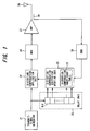
- Fig. 1 is a diagram showing the basic structure of the present invention.
- Numeral 21 denotes a transmit-signal generator, 22 distortion compensation coefficient table (a memory such as a RAM) for storing distortion compensation coefficients that correct distortion of the transmission power amplifier, and 23 an address generator, which has a delay unit DLC that stores a present transmit-signal value and one or more past transmit-signal values, for outputting an address signal of the distortion compensation coefficient table (RAM) on the basis of these signal values.
- DLC delay unit
- Numeral 24 denotes a distortion compensation application unit for applying distortion compensation processing to the transmit signal using the present transmit-signal value and one or more past transmit-signal values, 25 a distortion compensation coefficient updating unit for updating distortion compensation coefficients and storing them in the distortion compensation coefficient table 22, 26 a modulator for modulating the transmit signal, 27 a transmission power amplifier, 28 an antenna, 29 a directional coupler for branching part of the output signal of the transmission power amplifier, and 30 a demodulator for demodulating the output signal of the transmission power amplifier.
- Initial values of distortion compensation coefficients for correcting distortion of the transmission power amplifier 27 are stored in the memory 23 in advance. If a transmit signal is generated by the transmit-signal generator 21, the address generator 23 generates an address A corresponding to the present transmit signal and a past transmit signal, reads out a distortion compensation coefficient from this address and inputs the coefficient to the distortion compensation application unit 24. The latter applies distortion compensation processing to the transmit signal using this distortion compensation coefficient and outputs the processed signal.
- the modulator 26 modulates the transmit signal that has been compensated for distortion, and the transmission power amplifier 27 amplifies the modulated signal and transmits it from an antenna 28.
- the demodulator 30 demodulates the output signal of the transmission power amplifier 27 that enters from the directional coupler 29 and inputs the demodulated signal to the distortion compensation coefficient updating unit 25.
- the latter updates the above-mentioned distortion compensation coefficient in such a manner that the difference between the transmit signal before distortion compensation and the demodulated signal becomes zero and stores the updated coefficient at the address A.
- Fig. 2 is a diagram showing the structure of a first embodiment of the present invention.
- This is an example in which a distortion compensation scheme (polar-loop scheme) in a polar coordinate system is adopted as the distortion compensation scheme. Components identical with those of the first embodiment are designated by like reference characters.
- the first embodiment is an example in which a distortion compensation coefficient is found as a function of power p(t) of the present transmit signal and a difference ⁇ p between present transmission power and the transmission power that preceded it.
- Numeral 31 denotes a serial/parallel (S/P) converter 2 for dividing serial data, which is output from the transmit-signal generator 21, alternately one bit at a time to convert the data to two sequences, namely an in-phase component signal (I signal) and a quadrature component signal (Q signal).
- Numeral 32 denotes a DA converter for converting, to analog signals, the distortion-compensated quadrature signals (I and Q signals) output from the distortion compensation application unit 24.
- Numeral 33 denotes an AD converter for converting, to digital signals, quadrature-demodulated signals (I' and Q' signals) output from the demodulator 30.
- the distortion compensation application unit 24 subjects the quadrature signal to distortion compensation processing by executing complex multiplication between the quadrature signal I+jQ and distortion compensation coefficient h n-1 [p(t), ⁇ p) that has been read out from the address A [p(t), ⁇ p].
- the distortion compensation application unit 24 performs the following operation: (I+jQ) ⁇ (h i +jh q ) and output a distortion-compensated quadrature signal (I ⁇ h i -Q ⁇ h q ) + j(I ⁇ h q +Q ⁇ h i )
- the distortion compensation coefficient updating unit 25 updates the distortion compensation coefficient h n-1 [p(t), ⁇ p], which has been read out from the address A [p(t), ⁇ p], by adaptive signal processing using the LMS algorithm or RLS algorithm in such a manner that the difference between the quadrature signal before distortion compensation and the demodulated signal that is output from the demodulator (quadrature detector) 30 will become zero ⁇ h n-1 [p(t), ⁇ p] ⁇ h n [p(t), ⁇ p] ⁇ , and stores the distortion compensation coefficient h n [p(t), ⁇ p] after updating at the original address A [p(t), ⁇ p].
- initial values of distortion compensation coefficients h[p(t), ⁇ p] are stored in the distortion compensation coefficient table 22 in advance in correspondence with combinations of p(t) and ⁇ p. If a transmit signal is generated by the transmit-signal generator 21 under these conditions, the S/P converter 31 converts the transmit signal to a quadrature signal composed of an in-phase signal component (I signal) and quadrature component signal (Q signal) and inputs the result to the address generator 23, distortion compensation application unit 24 and distortion compensation coefficient updating unit 25.
- I signal in-phase signal component
- Q signal quadrature component signal
- the address generator 23 calculates the power value p(t) of the transmit signal from the quadrature signal, calculates the difference ⁇ p between the present power value and the power value that preceded it, generates the address A [p(t), ⁇ p], where p(t) is the high-order address and ⁇ p the low-order address, reads the distortion compensation coefficient h n-1 [p(t), ⁇ p] out of the distortion compensation coefficient table 22 and inputs this coefficient to the distortion compensation application unit 24.
- the latter applies distortion compensation processing to the quadrature signal by executing the calculation of Equation (1).
- the DA converter 32 converts each component of the distortion-compensated quadrature signal to an analog signal, the quadrature modulator 26 applies quadrature modulation to the distortion-compensated quadrature signal, and the transmission power amplifier 27 amplifies the quadrature-modulated signal and transmits the amplified signal from the antenna 28.
- the demodulator (quadrature detector) 30 demodulates the output signal of the transmission power amplifier 27 that enters from the directional coupler 29, and the AD converter 33 converts the components of the demodulated signal to digital signals and inputs the digital signals to the distortion compensation coefficient updating unit 25.
- the latter updates the distortion compensation coefficient by adaptive signal processing in such a manner that the difference between the quadrature signal before distortion compensation and the demodulated signal becomes zero ⁇ h n-1 [p(t), ⁇ p] ⁇ h n [p(t), ⁇ p] ⁇ , and stores the distortion compensation coefficient h n [p(t), ⁇ p] at the address A [p(t), ⁇ p] indicated by the delay circuit 23d. The above operation is then repeated so that the distortion compensation coefficient will converge to a constant value.
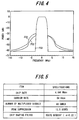
- Fig. 4 shows the results of a simulation of a frequency spectrum FS3 according to this embodiment. Here side lobes are suppressed.
- FS1 shows a spectrum characteristic in a case where distortion compensation processing is not executed, and FS2 shows a spectrum characteristic in a case where conventional distortion compensation processing has been executed.
- a 60-code (60-channel) multiplexed signal is used as the transmit signal, the peak value of the code-multiplexed signal is suppressed at 13.5 codes and the code-multiplexed signal is filtered by a route Nyquist filter the roll-off factor ⁇ of which is 0.22, as shown in Fig. 5, in order to observe the effects of linearization in a case where the apparatus is applied to a W-CDMA scheme.
- the chip frequency is 4.096 Mbps and the carrier rate is 64 kbps.
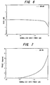
- Fig. 6 the characteristic of normalized input power vs. gain of the amplifier used in the simulation is illustrated in Fig. 6, and the characteristic of normalized input power vs. phase of the amplifier is illustrated in Fig. 7.
- the amplifier starts to saturate from the vicinity of -6 dB, as will be understood from the characteristic of input power vs. gain.
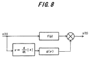
- the model of this amplifier is depicted in Fig. 8. According to the model, a gain fluctuation function g( ⁇ ) conforming to the time differential value ⁇ of an input envelope signal is introduced, and it is assumed that a signal y(t), which is obtained by multiplying, by g( ⁇ ), an input signal x(t) that has undergone distortion f(p) (where p represents transmission power), is output from the amplifier.
- the gain fluctuation function g( ⁇ ) is given by the following equation, where r represents a gain fluctuation coefficient and is eaual to 0.1:
- Fig. 9 shows an example in which the distortion compensation coefficient updating unit 25 of the first embodiment is implemented so as to update distortion compensation coefficients by adaptive signal processing based upon the LMS algorithm.
- Components in the embodiment of Fig. 9 identical with those of the first embodiment of Fig. 2 are designated by like reference characters. This embodiment differs in the following respects:
- a complex-conjugate signal output unit 43a outputs a complex-conjugate signal y*(t) of the demodulated signal y(t)
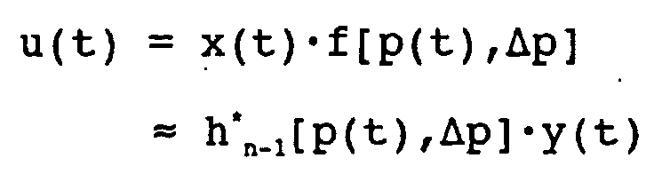
- a multiplier 43b performs multiplication between the distortion compensation coefficient h n-1 [(p), ⁇ p] and y*t) and outputs a complex-conjugate signal u*(t) of u(t)
- a multiplier 43c performs multiplication between the error signal e(t) and u*(t)
- a multiplier 43d performs multiplication by a step-size parameter ⁇ and outputs ⁇ e(t)u*(t).
- 2 ⁇ p p(t-1)-p(t) where x, y, f, h, u and e are complex numbers.
- the distortion compensation coefficient is updated in accordance with Equation (3) and the updated distortion compensation coefficient h n [p(t), ⁇ p] is stored in the distortion compensation coefficient table 22 instead of the distortion compensation coefficient h n-1 [p(t), ⁇ p] that prevailed prior to updating.
- Fig. 10 shows an example in which the distortion compensation coefficient updating unit 25 of the first embodiment is implemented so as to update distortion compensation coefficients by adaptive signal processing based upon the RLS algorithm.
- Components in the embodiment of Fig. 10 identical with those of the first embodiment of Fig. 2 are designated by like reference characters. This embodiment differs in the following respects:
- unit 43i' outputs a complex-conjugate signal T*(t) of T(t)
- a multiplier 43j' calculates K(t) ⁇ T*(t) and outputs the result
- a complex-conjugate signal output unit 43m' outputs a complex-conjugate signal K*(t) of K(t)
- a multiplier 43n' calculates e(t) ⁇ K*(t) and outputs the result.
- 2 ⁇ p p(t-1)-p(t) where x, y, f, h, u, e, K, P and T are complex numbers.
- the distortion compensation coefficient is updated in accordance with Equation (4) and the updated distortion compensation coefficient h n [p(t), ⁇ p] is stored in the distortion compensation coefficient table 22 instead of the distortion compensation coefficient h n-1 [p(t), ⁇ p] that prevailed prior to updating.
- the RLS algorithm has a convergence characteristic superior to that of the LMS algorithm and makes it possible to achieve convergence of the distortion compensation coefficient at high speed.
- a distortion compensation coefficient is a function of p(t), ⁇ p, and the distortion compensation coefficient is stored in the distortion compensation coefficient table 22 at an address A [p(t), ⁇ p] corresponding to p(t), ⁇ p.
- a distortion compensation coefficient is a function of p(t), P(t-1)
- the distortion compensation coefficient is stored in the distortion compensation coefficient table 22 at an address A [p(t),p(t-1)] corresponding to P(t), P(t-1).
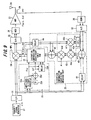
- Fig. 11 is a diagram showing the structure of this first modification. This modification differs from the first embodiment of Fig. 2 in the following respects:
- Initial values of distortion compensation coefficients h[p(t),p(t-1)] are stored in the distortion compensation coefficient table 22 in advance in correspondence with combinations of p(t) and p(t-1). If a transmit signal is generated by the transmit-signal generator 21 under these conditions, the S/P converter 31 converts the transmit signal to a quadrature signal composed of an in-phase signal component (I signal) and quadrature component signal (Q signal) and inputs the result to the address generator 23, distortion compensation application unit 24 and distortion compensation coefficient updating unit 25.
- I signal in-phase signal component
- Q signal quadrature component signal
- the address generator 23 calculates the power value p(t) of the transmit signal from the quadrature signal, generates the address A [p(t),p(t-1)], where p(t) is the high-order address and the power p(t-1) preceding it is the low-order address, reads the distortion compensation coefficient h n-1 [p(t),p(t-1)] out of the distortion compensation coefficient table 22 and inputs this coefficient to the distortion compensation application unit 24.
- the latter applies distortion compensation processing to the quadrature signal by executing the calculation of Equation (1).
- the DA converter 32 converts each component of the distortion-compensated quadrature signal to an analog signal, the quadrature modulator 26 applies quadrature modulation to the distortion-compensated quadrature signal, and the transmission power amplifier 27 amplifies the quadrature-modulated signal and transmits the amplified signal from the antenna 28.
- the demodulator (quadrature detector) 30 demodulates the output signal of the transmission power amplifier 27 that enters from the directional coupler 29, and the AD converter 33 converts the components of the demodulated signal to digital signals and inputs the digital signals to the distortion compensation coefficient updating unit 25.
- the latter updates the distortion compensation coefficient by adaptive signal processing in such a manner that the difference between the quadrature signal before distortion compensation and the demodulated signal becomes zero ⁇ h n-1 [p(t),p(t-1)] . ⁇ h n [p(t),p(t-1)] ⁇ , and stores the distortion compensation coefficient h n [p(t),p(t-1)] at the address A [p(t),p(t-1)] indicated by the delay circuit 23d. The above operation is then repeated so that the distortion compensation coefficient will converge to a constant value.
- a distortion compensation coefficient is a function of p(t), ⁇ p, and the distortion compensation coefficient is stored at an address A [p(t), ⁇ p] corresponding to p(t), ⁇ p in the distortion compensation coefficient table 22.
- a distortion compensation coefficient is a function of power p(t) and a differential value p(t)' of the envelope thereof, and the distortion compensation coefficient is stored in the distortion compensation coefficient table 22 at an address A [p(t),p(t)'] corresponding to P(t), P(t)'.
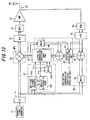
- Fig. 13 is a diagram showing the structure of this second modification. This modification differs from the first embodiment of Fig. 2 in the following respects:
- Initial values of distortion compensation coefficients h[p(t),p(t)'] are stored in the distortion compensation coefficient table 22 in advance in correspondence with combinations of p(t) and p(t)'. If a transmit signal is generated by the transmit-signal generator 21 under these conditions, the S/P converter 31 converts the transmit signal to a quadrature signal composed of an in-phase signal component (I signal) and quadrature component signal (Q signal) and inputs the result to the address generator 23, distortion compensation application unit 24 and distortion compensation coefficient updating unit 25.
- I signal in-phase signal component
- Q signal quadrature component signal
- the address generator 23 calculates the power value p(t) of the transmit signal from the quadrature signal, generates the address A [p(t), p(t)'], where p(t) is the high-order address and the differential value power p(t)' of the envelope of the transmission power is the low-order address, reads the distortion compensation coefficient h n-1 [p(t), p(t)'] out of the distortion compensation coefficient table 22 and inputs this coefficient to the distortion compensation application unit 24.
- the latter applies distortion compensation processing to the quadrature signal by executing the calculation of Equation (1).
- the DA converter 32 converts each component of the distortion-compensated quadrature signal to an analog signal
- the quadrature modulator 26 applies quadrature modulation to the distortion-compensated quadrature signal
- the transmission power amplifier 27 amplifies the quadrature-modulated signal and transmits the amplified signal from the antenna 28.
- the demodulator (quadrature detector) 30 demodulates the output signal of the transmission power amplifier 27 that enters from the directional coupler 29, and the AD converter 33 converts the components of the demodulated signal to digital signals and inputs the digital signals to the distortion compensation coefficient updating unit 25.
- the latter updates the distortion compensation coefficient by adaptive signal processing in such a manner that the difference between the quadrature signal before distortion compensation and the demodulated signal becomes zero ⁇ h n-1 [p(t),p(t)'] ⁇ h n [p(t),p(t)'] ⁇ , and stores the distortion compensation coefficient h n [p(t), p(t)'] at the address indicated by the delay circuit 23d.
- a distortion compensation coefficient is decided based upon present power value and the power value that preceded it.
- a distortion compensation coefficient can be decided based upon the power value of the present transmit signal and the power values of a plurality of past transmit signals, such as the present power value and the two power values that preceded it.
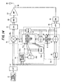
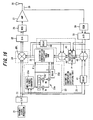
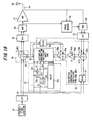
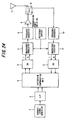
- Fig. 14 is a diagram showing the structure of the third modification. This modification differs from the first embodiment of Fig. 2 in the following respects:
- Fig. 16 is a diagram showing another structure of the third modification. This modification differs from the first embodiment of Fig. 2 in the following respects:
- Fig. 17 is a diagram showing another structure of the third modification. This modification differs from the first embodiment of Fig. 2 in the following respects:
- Fig. 19 is a diagram showing the structure of a second embodiment of the present invention.
- This is an example in which a distortion compensation scheme (Cartesian-loop scheme) in a rectangular coordinate system is adopted as the distortion compensation scheme. Components identical with those shown in Fig. 1 are designated by like reference characters.
- the second embodiment is an example in which a distortion compensation coefficient is found as a function of amplitude of the present transmit signal and the difference between the amplitudes of the present transmit signal and of the transmit signal that preceded it.
- Numeral 31 denotes the serial/parallel (S/P) converter 2 for dividing serial data, which is output from the transmit-signal generator 21, alternately one bit at a time to convert the data to two sequences, namely an in-phase component signal (I signal) and a quadrature component signal (Q signal).
- Numeral 32 denotes the DA converter for converting, to analog signals, the distortion-compensated quadrature signals (I and Q signals) output from the distortion compensation application unit 24.
- Numeral 33 denotes the AD converter for converting, to digital signals, quadrature-demodulated signals (I' and Q' signals) output from the demodulator 30.
- Numeral 34 denotes a phase rotator, to which the output of the quadrature modulator 26 and the output of the transmission power amplifier 27 are input, for eliminating phase rotation produced by the amplifier.
- the quadrature detector 30 demodulates and outputs the signal from which phase rotation has been eliminated.
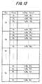
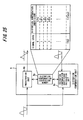
- the real part hi[I(t), ⁇ i] of a distortion compensation coefficient has been stored in the real-part table in correspondence with a combination of I(t) and ⁇ i, as shown in Fig. 20(a), and the imaginary part hq[Q(t), ⁇ q] of the distortion compensation coefficient has been stored in the imaginary-part table in correspondence with a combination of Q(t) and ⁇ q, as shown in Fig. 20(b).
- I(t), ⁇ i become the high-order and low-order addresses of an address Ai [I(t), ⁇ i] of the real-part table
- Q(t), ⁇ q become the high-order and low-order addresses of an address Aq [Q(t), ⁇ q] of the imaginary-part table.
- the distortion compensation application unit 24 which has two adders AD1, AD2 for the in-phase and quadrature components, adds the components I(t), Q(t) of the quadrature signal and distortion compensation coefficients hi[I(t), ⁇ i], hq[Q(t), ⁇ q], which have been read from the addresses Ai [I(t), ⁇ i], Aq [Q(t), ⁇ q], thereby applying distortion compensation to each component of the quadrature signal.
- the distortion compensation application unit 24 outputs the following: I(t) + hi[I(t), ⁇ i], Q(t) + hq[Q(t), ⁇ q]
- the distortion compensation coefficient updating unit 25 updates distortion compensation coefficients hi n-1 [I(t), ⁇ i], hq n-1 [Q(t), ⁇ q], which have been read from the addresses Ai [I(t), ⁇ i], Aq [Q(t), ⁇ q], in such a manner that the difference between the quadrature signal before compensation and the demodulated signal output from the demodulator (quadrature detector) 30 will become zero ⁇ hi n-1 [I(t), ⁇ i] ⁇ hi n [I(t), ⁇ i], hq n-1 [Q(t), ⁇ q] ⁇ hq n [Q(t), ⁇ q] ⁇ and stores the updated distortion compensation coefficients hi n [I(t), ⁇ i], hq n [Q(t), ⁇ q] at the original addresses Ai [I(t), ⁇ i], Aq [Q(t), ⁇ q].
- a delay circuit 51 delays the quadrature signal, which is output from the S/P converter 31, for a predetermined period of time
- multipliers 53a, 53b multiply each of the error signals by a constant G
- a delay circuit 54 delays the distortion compensation coefficients hi n-1 [I(t), ⁇ i], hq n-1 [Q(t), ⁇ q] for a predetermined period of time
- adders 55a, 55b perform the operations indicated by the following equations to thereby update the distortion compensation coefficients: hi n [I(t), ⁇ i
- initial values of a real parts hi[I(t), ⁇ i] and imaginary parts hq[Q(t), ⁇ q] of distortion compensation coefficients are stored in the real-part table and imaginary-part table of the distortion compensation coefficient table 22 in advance in correspondence with combinations of I(t) and ⁇ i and combinations of Q(t) and ⁇ q.
- the S/P converter 31 converts the transmit signal to a quadrature signal composed of an in-phase signal component (I signal) and quadrature component signal (Q signal) and inputs the result to the address generator 23, distortion compensation application unit 24 and distortion compensation coefficient updating unit 25.
- the address generator 23 generates addresses Ai [I(t), ⁇ i], Aq [Q(t), ⁇ q] of the real-part table and imaginary-part table of distortion compensation coefficient table 22 from the quadrature signal, reads distortion compensation coefficients hi n-1 [I(t), ⁇ i], hq n-1 [Q(t), ⁇ q] from the tables and inputs these coefficients to the distortion compensation application unit 24.
- the latter applies distortion compensation processing to the quadrature signal by executing the calculation of Equation (5).
- the DA converter 32 converts each component of the distortion-compensated quadrature signal to an analog signal, the quadrature.
- modulator 26 applies quadrature modulation to the distortion-compensated quadrature signal, and the transmission power amplifier 27 amplifies the quadrature-modulated signal and transmits the amplified signal from the antenna 28.
- the phase rotator 34 eliminates phase rotation, which has been produced by the transmission power amplifier 27, from the output signal of this amplifier, the quadrature detector 30 demodulates the signal from which phase rotation has been eliminated, and the AD converter 33 converts the components of the demodulated signal to digital signals and inputs the digital signals to the distortion compensation coefficient updating unit 25.
- the latter updates the distortion compensation coefficient in such a manner that the differences between the components of the quadrature signal before distortion compensation and of the demodulated signal become zero and stores the updated distortion compensation coefficients hi n [I(t), ⁇ i], hq n [Q(t), ⁇ q] at the original addresses Ai [I(t), ⁇ i], Aq [Q(t), ⁇ q].
- the above operation is then repeated so that the distortion compensation coefficient will converge to a constant value.
- the quadrature component is made a function of Q(t), ⁇ q
- the real-number part of the distortion compensation coefficient is stored at an address corresponding to I(t), ⁇ i of the real-part table
- the imaginary-number part of the distortion compensation coefficient is stored at an address corresponding to Q(t), ⁇ q of the imaginary-part table.
- the in-phase component of the distortion compensation coefficient is made a function of I(t), I(t-1)
- the quadrature component is made a function of Q(t), Q(t-1)
- the real-number part of the distortion compensation coefficient is stored at an address corresponding to I(t), I(t-1) of the real-part table
- the imaginary-number part of the distortion compensation coefficient is stored at an address corresponding to Q(t), Q(t-1) of the imaginary-part table.
- a distortion compensation coefficient is a function of amplitudes Q, P of a transmit signal and differences ⁇ i, ⁇ q between present amplitude and preceding amplitude of the transmit signal.
- a distortion compensation coefficient is a function of present amplitudes Q(t), I(t) and preceding amplitudes I(t-1), Q(t-1), and the distortion compensation coefficient conforming to the present amplitude and amplitude preceding it is stored in the distortion compensation coefficient table 22.
- Fig. 21 is a diagram showing the structure of this first modification. This modification differs from the second embodiment in the following respects:
- frequency asymmetric distortion can be compensated for so that a satisfactory distortion suppression effect can manifest itself. Further, in accordance with the present invention, it is possible to eliminate a variance in the distortion compensation effect caused by individual differences among devices.
Landscapes
- Physics & Mathematics (AREA)
- Nonlinear Science (AREA)
- Power Engineering (AREA)
- Engineering & Computer Science (AREA)
- Mathematical Analysis (AREA)
- Pure & Applied Mathematics (AREA)
- Mathematical Optimization (AREA)
- General Physics & Mathematics (AREA)
- Algebra (AREA)
- Amplifiers (AREA)
- Transmitters (AREA)
- Control Of Amplification And Gain Control (AREA)
- Digital Transmission Methods That Use Modulated Carrier Waves (AREA)
- Cable Transmission Systems, Equalization Of Radio And Reduction Of Echo (AREA)
Abstract
Description


and stores the updated distortion compensation coefficients hin[I(t),Δi], hqn[Q(t),Δq] at the original addresses Ai [I(t),Δi], Aq [Q(t),Δq].
Claims (19)
- A distortion compensation method for correcting distortion of a transmission power amplifier in a radio apparatus, characterized by:storing, in memory, distortion compensation coefficients for correcting distortion of the transmission power amplifier;reading a distortion compensation coefficient, which conforms to a present transmit signal and a past transmit signal, out of the memory, and applying distortion compensation processing to the present transmit signal using said distortion compensation coefficient;amplifying the transmit signal, to which distortion compensation processing has been applied, by the transmission power amplifier and transmitting the amplified signal; andupdating said distortion compensation coefficient based upon the transmit signal before distortion compensation and an output signal from the transmission power amplifier.
- A distortion compensation method according to claim 1, characterized in that each distortion compensation coefficient is stored in the memory in correspondence with present and past transmit signals.
- A distortion compensation method for correcting distortion of a transmission power amplifier in a radio apparatus, characterized by:storing, in memory, distortion compensation coefficients for correcting distortion of the transmission power amplifier;converting a transmit signal to a quadrature signal composed of an in-phase component and a quadrature component;reading a distortion compensation coefficient, which conforms to a present transmit signal and a past transmit, out of the memory in complex form;applying distortion compensation processing to said quadrature signal by performing complex multiplication between said quadrature signal and said distortion compensation coefficient;applying quadrature modulation to the distortion-compensated quadrature signal, amplifying the quadrature-modulated signal by the transmission power amplifier and transmitting the amplified signal;demodulating an output signal from the transmission power amplifier; andupdating said distortion compensation coefficient by adaptive signal processing using a difference between the quadrature signal before distortion compensation and the demodulated signal.
- A distortion compensation method according to claim 3, characterized in that a distortion compensation coefficient is updated and made to converge to a constant value by adaptive signal processing that uses an LMS algorithm or an RLS algorithm.
- A distortion compensation method for correcting distortion of a transmission power amplifier in a radio apparatus, characterized by:storing, in memory, distortion compensation coefficients for correcting distortion of the transmission power amplifier;converting a transmit signal to a quadrature signal composed of an in-phase component and a quadrature component;reading a distortion compensation coefficient, which conforms to a present transmit signal and a past transmit signal, out of the memory in complex form;applying distortion compensation processing to said quadrature signal by adding a real part and an imaginary part of said distortion compensation coefficient to each of the signal components of said quadrature signal;applying quadrature modulation to the distortion-compensated quadrature signal, amplifying the quadrature-modulated signal by the transmission power. amplifier and transmitting the amplified signal;eliminating phase rotation, which has been produced by said amplifier, from an output signal of the transmission power amplifier;demodulating the signal from which said phase rotation has been eliminated; andupdating the real part and the imaginary part of said distortion compensation coefficient in such a manner that a difference between in-phase components and a difference between quadrature components of the quadrature signal before distortion compensation and of the demodulated signal will become zero.
- A distortion compensation method according to claim 1 or 2, characterized in that one distortion compensation coefficient, which corresponds to a present transmit signal and a plurality of signals transmitted in the past, is read out of the memory and distortion compensation processing is executed.
- A distortion compensation method according to claim 1 or 2, characterized in that one distortion compensation coefficient that corresponds to two signals, namely a present transmit signal and a signal transmitted previously, is read out of the memory and distortion compensation processing is executed.
- A distortion compensation method according to claim 7, characterized in that a distortion compensation coefficient, which corresponds to a combination of a present transmit signal and a difference between the present transmit signal and a signal transmitted previously, is read out of the memory and distortion compensation processing is executed.
- A distortion compensation method according to claim 7, characterized in that a distortion compensation coefficient, which corresponds to a combination of an instantaneous value of a present transmit signal and an envelope differential value of the transmit signal, is read out of the memory and distortion compensation processing is executed.
- A distortion compensation method according to claim 1 or 2, characterized in that a distortion compensation coefficient, which corresponds to a power value of a present transmit signal and a power value of a signal transmitted in the past, is read out of the memory and distortion compensation processing is executed.
- A distortion compensation method according to claim 1 or 2, characterized in that a distortion compensation coefficient, which corresponds to an amplitude value of a present transmit signal and an amplitude value of a signal transmitted in the past, is read out of the memory and distortion compensation processing is executed.
- A distortion compensation apparatus for correcting distortion of a transmission power amplifier in a radio apparatus, characterized by having:a memory for storing distortion compensation coefficients for correcting distortion of the transmission power amplifier;a distortion compensation application unit for reading a distortion compensation coefficient, which conforms to a present transmit signal and a past transmit signal, out of the memory, applying distortion compensation processing to the present transmit signal using said distortion compensation coefficient, and inputting the processed signal to the transmission power amplifier; anda distortion compensation coefficient updating unit for updating said distortion compensation coefficient based upon the transmit signal before distortion compensation and an output signal from the transmission power amplifier, and inputting the updated coefficient to the memory.
- A distortion compensation apparatus according to claim 12, characterized in that said memory stores each distortion compensation coefficient in correspondence with a combination of a present transmit signal and a past transmit signal.
- A distortion compensation apparatus according to claim 12, characterized in that said distortion compensation application unit reads one distortion compensation coefficient, which corresponds to a present transmit signal and a plurality of signals transmitted in the past, out of the memory and applies distortion compensation.
- A distortion compensation apparatus according to. claim 12, characterized in that said distortion compensation application unit reads a distortion compensation coefficient, which corresponds to a combination of a present transmit signal and a signal transmitted previously, out of the memory and executes distortion compensation processing.
- A distortion compensation apparatus according to claim 15, characterized by further having an arithmetic unit for calculating a difference between a present signal value and a signal value transmitted previously;
wherein the distortion compensation application unit reads a distortion compensation coefficient, which corresponds to a combination of the present transmit signal and the difference between the present signal and the signal transmitted previously, out of the memory and executing distortion compensation processing. - A distortion compensation apparatus according to claim 15, characterized by further having means for calculating an envelope differential value of the transmit signal;
wherein the distortion compensation application unit reads a distortion compensation coefficient, which corresponds to a combination of an instantaneous value of the present transmit signal and the envelope differential value, out of the memory and executing distortion compensation processing. - A distortion compensation apparatus according to claim 12, characterized in that said distortion compensation application unit reads a distortion compensation coefficient, which corresponds to a power value of a present transmit signal and a power value of a signal transmitted in the past, out of the memory and executes distortion compensation processing.
- A distortion compensation apparatus according to claim 12, characterized in that said distortion compensation application unit reads a distortion compensation coefficient, which corresponds to an amplitude value of a present transmit signal and an amplitude value of a signal transmitted in the past, out of the memory and executes distortion compensation processing.
Applications Claiming Priority (1)
| Application Number | Priority Date | Filing Date | Title |
|---|---|---|---|
| PCT/JP1999/004037 WO2001008320A1 (en) | 1999-07-28 | 1999-07-28 | Method and apparatus for distortion compensation of radio device |
Publications (3)
| Publication Number | Publication Date |
|---|---|
| EP1204216A1 true EP1204216A1 (en) | 2002-05-08 |
| EP1204216A4 EP1204216A4 (en) | 2009-03-25 |
| EP1204216B1 EP1204216B1 (en) | 2011-04-20 |
Family
ID=14236325
Family Applications (1)
| Application Number | Title | Priority Date | Filing Date |
|---|---|---|---|
| EP99933123A Expired - Lifetime EP1204216B1 (en) | 1999-07-28 | 1999-07-28 | Method and apparatus for distortion compensation of radio device |
Country Status (5)
| Country | Link |
|---|---|
| US (1) | US7020447B2 (en) |
| EP (1) | EP1204216B1 (en) |
| JP (1) | JP4086133B2 (en) |
| DE (1) | DE69943380D1 (en) |
| WO (1) | WO2001008320A1 (en) |
Cited By (6)
| Publication number | Priority date | Publication date | Assignee | Title |
|---|---|---|---|---|
| WO2003103167A1 (en) | 2002-05-31 | 2003-12-11 | 富士通株式会社 | Table reference predistortor |
| WO2003105337A1 (en) | 2002-06-07 | 2003-12-18 | Telefonaktiebolaget Lm Ericsson (Publ) | Coordinate rotation of pre-distortion vector in feedforward linearization amplification system |
| KR100601580B1 (en) | 2004-12-02 | 2006-07-18 | 주식회사 팬택 | AAM signal control method and transmitter using the same in a mobile communication system performing high speed data transmission |
| EP1249931A3 (en) * | 2001-03-27 | 2006-08-02 | Pace Micro Technology PLC | Auto-adaptive pre-distortion scheme employing parametric modelling |
| EP1811655A1 (en) * | 2002-07-04 | 2007-07-25 | Fujitsu Ltd. | A power amplifier distortion compensation apparatus and method thereof |
| EP2221962A1 (en) * | 2009-02-05 | 2010-08-25 | Fujitsu Limited | Predistorter and distortion compensation method |
Families Citing this family (61)
| Publication number | Priority date | Publication date | Assignee | Title |
|---|---|---|---|---|
| JP4550303B2 (en) * | 2001-03-19 | 2010-09-22 | 三星電子株式会社 | Nonlinear distortion compensation method and nonlinear distortion compensation circuit |
| JP4550302B2 (en) * | 2001-03-19 | 2010-09-22 | 三星電子株式会社 | Nonlinear distortion compensation method and nonlinear distortion compensation circuit |
| JP3876408B2 (en) | 2001-10-31 | 2007-01-31 | 富士通株式会社 | Distortion compensation apparatus and distortion compensation method |
| US7657241B2 (en) * | 2002-02-01 | 2010-02-02 | Qualcomm, Incorporated | Distortion reduction calibration |
| US7248642B1 (en) | 2002-02-05 | 2007-07-24 | Andrew Corporation | Frequency-dependent phase pre-distortion for reducing spurious emissions in communication networks |
| US7266159B2 (en) * | 2002-03-08 | 2007-09-04 | Andrew Corporation | Frequency-dependent magnitude pre-distortion on non-baseband input signals for reducing spurious emissions in communication networks |
| US7197085B1 (en) | 2002-03-08 | 2007-03-27 | Andrew Corporation | Frequency-dependent magnitude pre-distortion for reducing spurious emissions in communication networks |
| JP3637323B2 (en) * | 2002-03-19 | 2005-04-13 | 株式会社東芝 | Reception device, transmission / reception device, and reception method |
| JP4230272B2 (en) * | 2002-06-05 | 2009-02-25 | パナソニック株式会社 | Distortion compensation device |
| US7489907B2 (en) * | 2002-10-23 | 2009-02-10 | Hitachi Kokusai Electric Inc. | Transmitter for suppressing a variation in input level of a multicarrier signal |
| JP3705271B2 (en) * | 2003-02-03 | 2005-10-12 | ソニー株式会社 | Transmission method and transmission apparatus |
| US7349490B2 (en) * | 2003-04-16 | 2008-03-25 | Powerwave Technologies, Inc. | Additive digital predistortion system employing parallel path coordinate conversion |
| US7251293B2 (en) * | 2003-06-27 | 2007-07-31 | Andrew Corporation | Digital pre-distortion for the linearization of power amplifiers with asymmetrical characteristics |
| US20040264596A1 (en) * | 2003-06-27 | 2004-12-30 | Andrew Corporation, A Delaware Corporation | Digital pre-distortion for the linearization of power amplifiers with asymmetrical characteristics |
| KR100495431B1 (en) * | 2003-07-18 | 2005-06-14 | 삼성전자주식회사 | Apparatus and Methods for calibrating up-converter |
| DE602004004291T2 (en) * | 2003-09-15 | 2007-05-24 | Ntt Docomo Inc. | DEVICE AND METHOD FOR ADAPTIVE ORTHOGONALITY CORRECTION |
| US7915954B2 (en) * | 2004-01-16 | 2011-03-29 | Qualcomm, Incorporated | Amplifier predistortion and autocalibration method and apparatus |
| US7366252B2 (en) * | 2004-01-21 | 2008-04-29 | Powerwave Technologies, Inc. | Wideband enhanced digital injection predistortion system and method |
| US7336725B2 (en) * | 2004-03-03 | 2008-02-26 | Powerwave Technologies, Inc. | Digital predistortion system and method for high efficiency transmitters |
| FI20040393A0 (en) * | 2004-03-12 | 2004-03-12 | Nokia Corp | Process for pre-distortion, measuring arrangement, pre-distortion structure, transmitter, receiver and switchgear |
| US20050242876A1 (en) * | 2004-04-28 | 2005-11-03 | Obernosterer Frank G E | Parameter estimation method and apparatus |
| US7239671B2 (en) * | 2004-07-09 | 2007-07-03 | Powerwave Technologies, Inc. | System and method for digital timing error correction in a communications system utilizing adaptive predistortion |
| EP1835626B1 (en) * | 2005-01-04 | 2010-12-15 | Fujitsu Ltd. | Dc offset compensation method and device |
| US7433420B1 (en) * | 2005-02-18 | 2008-10-07 | Beceem Communications Inc. | Phase rotation estimation |
| KR100939882B1 (en) * | 2005-03-09 | 2010-01-29 | 후지쯔 가부시끼가이샤 | Distortion compensation device |
| WO2006095422A1 (en) * | 2005-03-09 | 2006-09-14 | Fujitsu Limited | Strain compensation device |
| CN100576724C (en) * | 2005-05-18 | 2009-12-30 | 株式会社Ntt都科摩 | Power Series Type Predistorter and Its Control Method |
| US20070018718A1 (en) * | 2005-06-20 | 2007-01-25 | National Sun Yat-Sen University | Microwave transmitter and the method for increasing envelope bandwidth |
| US8170487B2 (en) * | 2006-02-03 | 2012-05-01 | Qualcomm, Incorporated | Baseband transmitter self-jamming and intermodulation cancellation device |
| JP4835241B2 (en) * | 2006-04-11 | 2011-12-14 | 株式会社日立製作所 | Digital predistortion transmitter |
| JP4812643B2 (en) * | 2007-02-01 | 2011-11-09 | 株式会社日立国際電気 | Amplification equipment |
| US7889751B2 (en) * | 2007-03-06 | 2011-02-15 | Sudhir Aggarwal | Low power wireless communication system |
| JP2009232425A (en) * | 2008-03-25 | 2009-10-08 | Toshiba Corp | Transmitter |
| JP5125797B2 (en) | 2008-06-19 | 2013-01-23 | 富士通株式会社 | Amplitude suppressor and signal transmitter |
| JP5144387B2 (en) * | 2008-06-20 | 2013-02-13 | 日本無線株式会社 | Distortion compensation circuit |
| JP5144386B2 (en) * | 2008-06-20 | 2013-02-13 | 日本無線株式会社 | Distortion compensation circuit |
| JP5233444B2 (en) | 2008-06-30 | 2013-07-10 | 富士通株式会社 | Distortion compensation amplifier and predistortion compensation amplifier |
| US8233493B2 (en) | 2008-09-08 | 2012-07-31 | Wisconsin Alumni Research Foundation | Packet router having improved packet classification |
| JP2010187178A (en) * | 2009-02-12 | 2010-08-26 | Toshiba Corp | Wireless transmission device and wireless transmission method |
| US8737523B2 (en) * | 2009-06-04 | 2014-05-27 | Xilinx, Inc. | Apparatus and method for predictive over-drive detection |
| JP5251749B2 (en) * | 2009-06-17 | 2013-07-31 | 富士通株式会社 | Phase correction apparatus and phase correction method |
| JP5293441B2 (en) * | 2009-06-17 | 2013-09-18 | 富士通株式会社 | Phase correction apparatus and phase correction method |
| JP4918572B2 (en) * | 2009-07-02 | 2012-04-18 | 株式会社日立国際電気 | Predistortion type amplifier with distortion compensation function |
| US8498591B1 (en) * | 2009-08-21 | 2013-07-30 | Marvell International Ltd. | Digital Predistortion for nonlinear RF power amplifiers |
| US8699620B1 (en) * | 2010-04-16 | 2014-04-15 | Marvell International Ltd. | Digital Predistortion for nonlinear RF power amplifiers |
| DE102010035918B4 (en) * | 2010-08-31 | 2014-01-09 | Siemens Aktiengesellschaft | Method and device for controlling a signal with a plurality of independent components |
| US8711976B2 (en) | 2011-05-12 | 2014-04-29 | Andrew Llc | Pre-distortion architecture for compensating non-linear effects |
| JP5751056B2 (en) | 2011-07-14 | 2015-07-22 | 富士通株式会社 | Distortion compensation apparatus, transmitter, and distortion compensation method |
| WO2013049242A1 (en) * | 2011-09-26 | 2013-04-04 | Aviat Networks, Inc. | Systems and methods for asynchronous re-modulation with adaptive i/q adjustment |
| US8837633B2 (en) | 2011-10-21 | 2014-09-16 | Xilinx, Inc. | Systems and methods for digital processing based on active signal channels of a communication system |
| US9571042B2 (en) * | 2012-07-26 | 2017-02-14 | Telefonaktiebolaget L M Ericsson (Publ) | Digital upconversion for multi-band multi-order power amplifiers |
| JP6324314B2 (en) * | 2012-09-19 | 2018-05-16 | 古野電気株式会社 | Pulse compression radar |
| US8874052B2 (en) * | 2012-11-15 | 2014-10-28 | Motorola Mobility Llc | Method and apparatus for improving efficiency and distortion leakage in a wireless power amplifier |
| JP6054739B2 (en) | 2012-12-26 | 2016-12-27 | パナソニック株式会社 | Distortion compensation apparatus and distortion compensation method |
| US8948325B1 (en) * | 2013-03-15 | 2015-02-03 | Pmc-Sierra Us, Inc. | Method and apparatus for digital post-distortion compensation of signal non-linearities |
| CA2814303A1 (en) | 2013-04-26 | 2014-10-26 | Cellphone-Mate, Inc. | Apparatus and methods for radio frequency signal boosters |
| JP6221518B2 (en) | 2013-05-24 | 2017-11-01 | 富士通株式会社 | Power amplification apparatus, transmitter, and power amplification apparatus control method |
| US9160586B1 (en) | 2013-07-24 | 2015-10-13 | Marvell International Ltd. | Method and apparatus for estimating and compensating for in-phase and quadrature (IQ) mismatch in a receiver of a wireless communication device |
| JP2016072696A (en) * | 2014-09-26 | 2016-05-09 | 富士通株式会社 | Distortion compensation device and distortion compensation method |
| US9362942B1 (en) * | 2015-01-12 | 2016-06-07 | Maxim Integrated Products, Inc. | System characteristic identification systems and methods |
| JP2021145218A (en) | 2020-03-11 | 2021-09-24 | 富士通株式会社 | Wireless communication device and coefficient update method |
Family Cites Families (21)
| Publication number | Priority date | Publication date | Assignee | Title |
|---|---|---|---|---|
| JPS5884558A (en) * | 1981-11-14 | 1983-05-20 | Nec Corp | Compensation circuit for nonlinear distortion |
| JPS61220546A (en) * | 1985-03-26 | 1986-09-30 | Nec Corp | Modulator |
| JPS61214843A (en) * | 1985-03-20 | 1986-09-24 | Nec Corp | Modulator |
| US4700151A (en) * | 1985-03-20 | 1987-10-13 | Nec Corporation | Modulation system capable of improving a transmission system |
| JPH0773243B2 (en) * | 1985-12-12 | 1995-08-02 | 日本電気株式会社 | Transmitter |
| JPS63121326A (en) * | 1986-11-10 | 1988-05-25 | Nec Corp | Transmitter |
| EP0465709A1 (en) * | 1990-07-12 | 1992-01-15 | Thomcast Ag | Method for compensating the nonlinear distortions of an amplifier |
| JP2967699B2 (en) * | 1995-03-06 | 1999-10-25 | 日本電気株式会社 | Transmission device |
| JPH09116474A (en) * | 1995-10-13 | 1997-05-02 | Sony Corp | Wireless communication device |
| JPH09164741A (en) | 1995-12-19 | 1997-06-24 | Ricoh Co Ltd | Image forming device |
| FR2746564B1 (en) * | 1996-03-22 | 1998-06-05 | Matra Communication | METHOD FOR CORRECTING NON-LINEARITIES OF AN AMPLIFIER, AND RADIO TRANSMITTER IMPLEMENTING SUCH A METHOD |
| JPH10136048A (en) * | 1996-10-29 | 1998-05-22 | Hitachi Denshi Ltd | Negative feedback amplifier |
| JPH10145146A (en) | 1996-11-05 | 1998-05-29 | Matsushita Electric Ind Co Ltd | Nonlinear distortion compensator |
| DE69728651T2 (en) * | 1996-11-19 | 2004-08-19 | Matsushita Electric Industrial Co., Ltd., Kadoma | Transmitter with linearized amplifier |
| US5923712A (en) * | 1997-05-05 | 1999-07-13 | Glenayre Electronics, Inc. | Method and apparatus for linear transmission by direct inverse modeling |
| US5867065A (en) * | 1997-05-07 | 1999-02-02 | Glenayre Electronics, Inc. | Frequency selective predistortion in a linear transmitter |
| JP3171157B2 (en) * | 1997-12-10 | 2001-05-28 | 松下電器産業株式会社 | Nonlinear distortion compensator |
| US6288610B1 (en) * | 1998-03-19 | 2001-09-11 | Fujitsu Limited | Method and apparatus for correcting signals, apparatus for compensating for distortion, apparatus for preparing distortion compensating data, and transmitter |
| US6587514B1 (en) * | 1999-07-13 | 2003-07-01 | Pmc-Sierra, Inc. | Digital predistortion methods for wideband amplifiers |
| US6356146B1 (en) * | 1999-07-13 | 2002-03-12 | Pmc-Sierra, Inc. | Amplifier measurement and modeling processes for use in generating predistortion parameters |
| US6342810B1 (en) * | 1999-07-13 | 2002-01-29 | Pmc-Sierra, Inc. | Predistortion amplifier system with separately controllable amplifiers |
-
1999
- 1999-07-28 JP JP2001512717A patent/JP4086133B2/en not_active Expired - Fee Related
- 1999-07-28 WO PCT/JP1999/004037 patent/WO2001008320A1/en not_active Ceased
- 1999-07-28 EP EP99933123A patent/EP1204216B1/en not_active Expired - Lifetime
- 1999-07-28 DE DE69943380T patent/DE69943380D1/en not_active Expired - Lifetime
-
2001
- 2001-12-06 US US10/010,263 patent/US7020447B2/en not_active Expired - Lifetime
Cited By (10)
| Publication number | Priority date | Publication date | Assignee | Title |
|---|---|---|---|---|
| EP1249931A3 (en) * | 2001-03-27 | 2006-08-02 | Pace Micro Technology PLC | Auto-adaptive pre-distortion scheme employing parametric modelling |
| WO2003103167A1 (en) | 2002-05-31 | 2003-12-11 | 富士通株式会社 | Table reference predistortor |
| EP1511182A4 (en) * | 2002-05-31 | 2007-05-02 | Fujitsu Ltd | TABLE-REFERENCE PREDISTORSION APPARATUS |
| US7392020B2 (en) | 2002-05-31 | 2008-06-24 | Fujitsu Limited | Table reference type predistorter |
| WO2003105337A1 (en) | 2002-06-07 | 2003-12-18 | Telefonaktiebolaget Lm Ericsson (Publ) | Coordinate rotation of pre-distortion vector in feedforward linearization amplification system |
| US6680649B2 (en) | 2002-06-07 | 2004-01-20 | Telefonaktiebolaget Lm Ericsson (Publ) | Coordinate rotation of pre-distortion vector in feedforward linearization amplification system |
| EP1811655A1 (en) * | 2002-07-04 | 2007-07-25 | Fujitsu Ltd. | A power amplifier distortion compensation apparatus and method thereof |
| KR100601580B1 (en) | 2004-12-02 | 2006-07-18 | 주식회사 팬택 | AAM signal control method and transmitter using the same in a mobile communication system performing high speed data transmission |
| EP2221962A1 (en) * | 2009-02-05 | 2010-08-25 | Fujitsu Limited | Predistorter and distortion compensation method |
| US8619905B2 (en) | 2009-02-05 | 2013-12-31 | Fujitsu Limited | Predistorter and distortion compensation method |
Also Published As
| Publication number | Publication date |
|---|---|
| JP4086133B2 (en) | 2008-05-14 |
| EP1204216A4 (en) | 2009-03-25 |
| US7020447B2 (en) | 2006-03-28 |
| EP1204216B1 (en) | 2011-04-20 |
| WO2001008320A1 (en) | 2001-02-01 |
| DE69943380D1 (en) | 2011-06-01 |
| US20020065048A1 (en) | 2002-05-30 |
Similar Documents
| Publication | Publication Date | Title |
|---|---|---|
| EP1204216B1 (en) | Method and apparatus for distortion compensation of radio device | |
| JPWO2001008320A1 (en) | Distortion compensation method and distortion compensation device for wireless device | |
| US8026762B2 (en) | High efficiency transmitter for wireless communication | |
| US6266517B1 (en) | Method and apparatus for correcting distortion in a transmitter | |
| US6072364A (en) | Adaptive digital predistortion for power amplifiers with real time modeling of memoryless complex gains | |
| CN101156159B (en) | Digital predistortion system and method for high efficiency transmitter | |
| US7995674B2 (en) | Digital predistortion transmitter | |
| US6647073B2 (en) | Linearisation and modulation device | |
| EP1025638B1 (en) | Linearization method and amplifier arrangement | |
| KR100448892B1 (en) | Apparatus and Method for Pre-distortion for Nonlinear Distortion of High Power Amplifier | |
| KR100279948B1 (en) | Apparatus and method for linearized power amplification | |
| US7321635B2 (en) | Linearization of amplifiers using baseband detection and non-baseband pre-distortion | |
| EP1705801B1 (en) | Distortion compensation apparatus | |
| EP1376856A2 (en) | Nonlinear distortion compensating circuit | |
| JP2002522989A (en) | Apparatus and method for power amplification linearization in mobile communication system | |
| EP1703688A2 (en) | Distortion compensation apparatus | |
| US20120098596A1 (en) | Power amplifier apparatus, distortion compensation coefficient updating method, and transmission apparatus | |
| US20020012404A1 (en) | Predistortion linearizer and method thereof | |
| KR20000031138A (en) | Pre-compensator of transmission system including linear distortion and nonlinear distortion and method for estimating delay between transmission signal and feedback signal and phase difference therebetween | |
| JP4012725B2 (en) | Predistortion type amplifier | |
| JP4935897B2 (en) | Distortion compensation apparatus and delay time estimation method thereof | |
| EP1701451B1 (en) | Distortion compensation apparatus | |
| JPH08251246A (en) | Transmitter | |
| JP2001267850A (en) | Radio apparatus and transmission wave distortion compensation method | |
| EP2625785A1 (en) | Signal processing arrangement and signal processing method |
Legal Events
| Date | Code | Title | Description |
|---|---|---|---|
| PUAI | Public reference made under article 153(3) epc to a published international application that has entered the european phase |
Free format text: ORIGINAL CODE: 0009012 |
|
| 17P | Request for examination filed |
Effective date: 20011206 |
|
| AK | Designated contracting states |
Kind code of ref document: A1 Designated state(s): AT BE CH CY DE DK ES FI FR GB GR IE IT LI LU MC NL PT SE |
|
| RBV | Designated contracting states (corrected) |
Designated state(s): DE FR GB |
|
| A4 | Supplementary search report drawn up and despatched |
Effective date: 20090224 |
|
| 17Q | First examination report despatched |
Effective date: 20090616 |
|
| RIC1 | Information provided on ipc code assigned before grant |
Ipc: H04L 27/00 20060101ALI20100825BHEP Ipc: H03G 3/30 20060101ALI20100825BHEP Ipc: H03F 1/32 20060101ALI20100825BHEP Ipc: H04B 3/04 20060101AFI20100825BHEP |
|
| GRAP | Despatch of communication of intention to grant a patent |
Free format text: ORIGINAL CODE: EPIDOSNIGR1 |
|
| GRAS | Grant fee paid |
Free format text: ORIGINAL CODE: EPIDOSNIGR3 |
|
| GRAA | (expected) grant |
Free format text: ORIGINAL CODE: 0009210 |
|
| AK | Designated contracting states |
Kind code of ref document: B1 Designated state(s): DE FR GB |
|
| REG | Reference to a national code |
Ref country code: GB Ref legal event code: FG4D |
|
| REF | Corresponds to: |
Ref document number: 69943380 Country of ref document: DE Date of ref document: 20110601 Kind code of ref document: P |
|
| REG | Reference to a national code |
Ref country code: DE Ref legal event code: R096 Ref document number: 69943380 Country of ref document: DE Effective date: 20110601 |
|
| PLBE | No opposition filed within time limit |
Free format text: ORIGINAL CODE: 0009261 |
|
| STAA | Information on the status of an ep patent application or granted ep patent |
Free format text: STATUS: NO OPPOSITION FILED WITHIN TIME LIMIT |
|
| 26N | No opposition filed |
Effective date: 20120123 |
|
| REG | Reference to a national code |
Ref country code: DE Ref legal event code: R097 Ref document number: 69943380 Country of ref document: DE Effective date: 20120123 |
|
| REG | Reference to a national code |
Ref country code: FR Ref legal event code: PLFP Year of fee payment: 18 |
|
| REG | Reference to a national code |
Ref country code: FR Ref legal event code: PLFP Year of fee payment: 19 |
|
| PGFP | Annual fee paid to national office [announced via postgrant information from national office to epo] |
Ref country code: FR Payment date: 20170613 Year of fee payment: 19 |
|
| PGFP | Annual fee paid to national office [announced via postgrant information from national office to epo] |
Ref country code: DE Payment date: 20170725 Year of fee payment: 19 Ref country code: GB Payment date: 20170726 Year of fee payment: 19 |
|
| REG | Reference to a national code |
Ref country code: DE Ref legal event code: R119 Ref document number: 69943380 Country of ref document: DE |
|
| GBPC | Gb: european patent ceased through non-payment of renewal fee |
Effective date: 20180728 |
|
| PG25 | Lapsed in a contracting state [announced via postgrant information from national office to epo] |
Ref country code: GB Free format text: LAPSE BECAUSE OF NON-PAYMENT OF DUE FEES Effective date: 20180728 Ref country code: DE Free format text: LAPSE BECAUSE OF NON-PAYMENT OF DUE FEES Effective date: 20190201 Ref country code: FR Free format text: LAPSE BECAUSE OF NON-PAYMENT OF DUE FEES Effective date: 20180731 |