EP1204126A1 - Niobium powder, its sintered body, and capacitor comprising the same - Google Patents
Niobium powder, its sintered body, and capacitor comprising the same Download PDFInfo
- Publication number
- EP1204126A1 EP1204126A1 EP00946343A EP00946343A EP1204126A1 EP 1204126 A1 EP1204126 A1 EP 1204126A1 EP 00946343 A EP00946343 A EP 00946343A EP 00946343 A EP00946343 A EP 00946343A EP 1204126 A1 EP1204126 A1 EP 1204126A1
- Authority
- EP
- European Patent Office
- Prior art keywords
- sintered body
- leakage current
- capacitor
- niobium
- niobium powder
- Prior art date
- Legal status (The legal status is an assumption and is not a legal conclusion. Google has not performed a legal analysis and makes no representation as to the accuracy of the status listed.)
- Granted
Links
Classifications
-
- B—PERFORMING OPERATIONS; TRANSPORTING
- B22—CASTING; POWDER METALLURGY
- B22F—WORKING METALLIC POWDER; MANUFACTURE OF ARTICLES FROM METALLIC POWDER; MAKING METALLIC POWDER; APPARATUS OR DEVICES SPECIALLY ADAPTED FOR METALLIC POWDER
- B22F1/00—Metallic powder; Treatment of metallic powder, e.g. to facilitate working or to improve properties
-
- H—ELECTRICITY
- H01—ELECTRIC ELEMENTS
- H01G—CAPACITORS; CAPACITORS, RECTIFIERS, DETECTORS, SWITCHING DEVICES, LIGHT-SENSITIVE OR TEMPERATURE-SENSITIVE DEVICES OF THE ELECTROLYTIC TYPE
- H01G9/00—Electrolytic capacitors, rectifiers, detectors, switching devices, light-sensitive or temperature-sensitive devices; Processes of their manufacture
- H01G9/004—Details
- H01G9/04—Electrodes or formation of dielectric layers thereon
- H01G9/048—Electrodes or formation of dielectric layers thereon characterised by their structure
- H01G9/052—Sintered electrodes
- H01G9/0525—Powder therefor
-
- C—CHEMISTRY; METALLURGY
- C22—METALLURGY; FERROUS OR NON-FERROUS ALLOYS; TREATMENT OF ALLOYS OR NON-FERROUS METALS
- C22C—ALLOYS
- C22C32/00—Non-ferrous alloys containing at least 5% by weight but less than 50% by weight of oxides, carbides, borides, nitrides, silicides or other metal compounds, e.g. oxynitrides, sulfides, whether added as such or formed in situ
- C22C32/0047—Non-ferrous alloys containing at least 5% by weight but less than 50% by weight of oxides, carbides, borides, nitrides, silicides or other metal compounds, e.g. oxynitrides, sulfides, whether added as such or formed in situ with carbides, nitrides, borides or silicides as the main non-metallic constituents
- C22C32/0068—Non-ferrous alloys containing at least 5% by weight but less than 50% by weight of oxides, carbides, borides, nitrides, silicides or other metal compounds, e.g. oxynitrides, sulfides, whether added as such or formed in situ with carbides, nitrides, borides or silicides as the main non-metallic constituents only nitrides
-
- C—CHEMISTRY; METALLURGY
- C22—METALLURGY; FERROUS OR NON-FERROUS ALLOYS; TREATMENT OF ALLOYS OR NON-FERROUS METALS
- C22C—ALLOYS
- C22C1/00—Making non-ferrous alloys
- C22C1/04—Making non-ferrous alloys by powder metallurgy
- C22C1/045—Alloys based on refractory metals
-
- C—CHEMISTRY; METALLURGY
- C22—METALLURGY; FERROUS OR NON-FERROUS ALLOYS; TREATMENT OF ALLOYS OR NON-FERROUS METALS
- C22C—ALLOYS
- C22C27/00—Alloys based on rhenium or a refractory metal not mentioned in groups C22C14/00 or C22C16/00
- C22C27/02—Alloys based on vanadium, niobium, or tantalum
Definitions
- This invention relates to a niobium powder used for a capacitor having excellent leakage current characteristics; a sintered body produced from the niobium powder; and a capacitor having the sintered body.
- Capacitors to be incorporated in electronic apparatuses such as portable phones and personal computers are demanded to have a small size and a high capacitance.
- a tantalum capacitor has been widely used, in view of high capacitance relative to its size, and excellent performance.
- a sintered body of tantalum powder is used as a positive electrode, and therefore, in order to increase the capacitance of the capacitor, the weight of the sintered body must be increased.
- the capacitor When the weight of the sintered body is increased, the capacitor necessarily becomes larger in size and fails to satisfy the demand for a small-sized capacitor.
- a capacitor containing a sintered body of a powdery material having a dielectric constant higher than that of tantalum has been studied. Niobium and titanium are mentioned as examples of the powdery material having a high dielectric constant.
- a sintered body of the above-described material has a high specific leakage current index. Since niobium and titanium have high dielectric constants, a capacitor having high capacitance can be produced from these materials, but lower specific leakage current index is required in order to produce a capacitor of high reliability. Specific leakage current index, i.e., leakage current per unit capacitance, can be used to evaluate whether high capacitance can be obtained while maintaining leakage current at a practically permissible low level.
- a specific leakage current index is not more than 1,500 [pA/( ⁇ F ⁇ V)], as calculated from capacitance and leakage current described in a catalogue entitled "CAPACITOR GRADE TANTALUM" by Showa Cabot Supermetals K.K.
- the actual measured value of specific leakage current index must be at most 1/3 to 1/4 of the value calculated from the catalogue, and a preferred leakage current index is not more than 400 [pA/( ⁇ F ⁇ V)].
- a conventional sintered body of niobium or titanium powder has a specific leakage current index much higher than the preferred leakage current index, and thus a capacitor containing the sintered body of niobium or titanium has poor reliability and is impractical for use.
- the object of the present invention is to provide a niobium powder suitable for the production of a capacitor having a low specific leakage current index; a sintered body of the niobium powder; and a capacitor with a low specific leakage current index, which has an electrode composed of the sintered body.
- a niobium powder characterized as having a nitrogen content of at least 500 ppm by weight and not more than 7,000 ppm by weight and having a mean particle diameter of at least 0.2 ⁇ m and smaller than 3 ⁇ m.
- a sintered body produced from a niobium powder, which exhibits a specific leakage current index of not more than 400 [pA/( ⁇ F ⁇ V)].
- a sintered body produced from the niobium powder concerned with the first aspect of the present invention.
- a capacitor comprising (i) an electrode, wherein the electrode is the sintered body concerned with the second or third aspect of the present invention, (ii) a dielectric formed on a surface of the sintered body, and (iii) a counter electrode.
- the niobium powder of the present invention is characterized as having a nitrogen content of at least 500 ppm by weight and not more than 7,000 ppm by weight and having a mean particle diameter of at least 0.2 ⁇ m and smaller than 3 ⁇ m.
- a capacitor produced from the niobium powder exhibits a very low specific leakage current index.
- the niobium powder of the present invention has a mean particle diameter of smaller than 3 ⁇ m, the specific surface area of the powder is large. Consequently, the (C ⁇ V) value, which is the denominator in the above-described formula providing specific leakage current index, is large.
- the mean particle diameter of the niobium powder is smaller than 0.2 ⁇ m, a sintered body produced from the niobium powder has a problem such that permeation of a negative electrode material into the sintered body becomes difficult. As a result, capacitance of the produced capacitor cannot be increased to the desired extent, and the (C ⁇ V) value cannot be made large, so that the sintered body is unsuitable for practical use.
- niobium may be bonded more strongly with oxygen than may tantalum, and thus, oxygen atoms in an electrolytic-oxidized film formed on niobium tend to diffuse toward the interior metal, i.e., niobium.
- a niobium powder is partially bonded with nitrogen, and thus oxygen in an electrolytic-oxidized film formed on niobium is hardly bonded with niobium, preventing diffusion of oxygen atoms toward the niobium. Consequently, the oxidized film can be stabilized and leakage current (LC) may be decreased.
- LC leakage current
- the niobium powder according to the present invention comprises a nitrogen content of at least 500 ppm by weight and not more than 7,000 ppm by weight, leakage current, serving as the numerator of the above-described formula, becomes especially low. Therefore, specific leakage current index of the sintered body according to the present invention may become particularly low.
- the sintered body of the present invention has a satisfactory specific leakage current index as low as not more than 400 [pA/( ⁇ F ⁇ V)]. Furthermore, in the present invention, when a nitrogen content in the niobium powder and the mean particle diameter of the niobium powder are optimized, the specific leakage current index may become not more than 200 [pA/( ⁇ F ⁇ V)].
- a niobium powder having a mean particle diameter of at least 0.2 ⁇ m and less than 3 ⁇ m serves as a raw material for forming the sintered body.
- the mean particle diameter is more preferably at least 0.5 ⁇ m and less than 2 ⁇ m. If the mean particle diameter is less than 0.2 ⁇ m, when a capacitor is fabricated from a sintered body produced from the niobium powder, a negative electrode material described below becomes difficult to soak into he sintered body because pores in the sintered body become very small. In contrast, if the mean particle diameter is 3 ⁇ m or larger, the sintered body having a desirable specific leakage current index is difficult to obtain.
- mean particle diameter refers to D 50 value, i.e., particle diameter value having a cumulative weight % of 50, which is measured by a particle size distribution measurement apparatus (commercial name, Microtrac).
- the niobium powder having the above-described mean particle diameter can be produced by means of, for example, pulvarization of a sodium-reduced compound of potassium fluoroniobate, pulvarization of a hydrogenated niobium ingot followed by dehydrogenation, or carbon-reduction of niobium oxide.
- the mean particle diameter of niobium powder can be controlled, for example, by the degree of hydrogenation of a niobium ingot, the pulverization time, and pulverization apparatus, when the niobium powder is obtained by pulverization of hydrogenated niobium ingot followed by dehydrogenation.
- the thus-obtained niobium powder may contain impurities attributed to the raw material, the reducing agent, and the apparatus employed. Typical impurities are elements such as iron, nickel, cobalt, silicon, sodium, potassium and magnesium.
- the above-described niobium powder can be washed with an alkali and at least one acid selected from hydrofluoric acid, nitric acid, sulfuric acid and hydrochloric acid.
- the niobium powder can be washed with the above acid, an alkali, and aqueous hydrogen peroxide. These reagents may be used sequentially or in combination, so as to wash the niobium powder repeatedly for removal of impurities.
- the niobium powder may be sufficiently washed, for example, with sulfuric acid, and residual sulfuric acid may be neutralized by use of an alkali, after which, the niobium powder may be repeatedly washed with water.
- nitric acid is used together with hydrogen peroxide for washing the niobium powder
- oxidation of the powder by nitric acid can be advantageously prevented.
- the niobium powder may also be washed by means of another method, for example, the niobium powder is stirred in the above-described reagents for an appropriate period of time, i.e., until the impurity content reaches a predetermined value or less, and the powder is separated from the reagent with stirring.
- impurity content of the niobium powder should preferably be reduced as low as possible.
- impurity content on the surface of a powder increases in accordance with the surface area, and therefore, in the above-described formula for calculating "specific leakage current index, " "leakage current (LC)” serving as the numerator tends to become larger than "(C ⁇ V)” serving as the denominator.
- LC leakage current
- an increase of "(C ⁇ V)" serving as the denominator can become larger in relation to “leakage current (LC)” serving as the numerator, as compared with typical cases.
- the elements When the niobium powder containing the above-mentioned elements as an impurity is used for producing a capacitor, the elements may migrate into a dielectric layer. Therefore, when voltage is applied to the capacitor, the elements may cause abnormal accumulation of electric charge, and specific leakage current index of the capacitor may become larger.
- the amount of each of the impurity elements should preferably be not more than 100 ppm by weight, or the total amount of the elements should be not more than 350 ppm by weight. By reducing the impurity content, a baneful influence on the above-described dielectric layer can be reduced.
- the amount of each of the impurity elements is preferably not more than 70 ppm by weight, and more preferably not more than 30 ppm by weight.
- the total amount of the impurity elements is preferably not more than 300 ppm by weight, and more preferably not more than 200 ppm by weight.
- the niobium powder according to the present invention has the above-described mean particle diameter, and a nitrogen content of at least 500 ppm and not more than 7,000 ppm by weight.
- the nitrogen content is preferably at least 1,000 ppm and not more than 3,000 ppm by weight.
- nitrogen content refers not to the amount of nitrogen adsorbed onto the niobium powder, but to the amount of nitrogen which has been chemically bound to niobium.
- Liquid nitrogen, nitrogen ions, and nitrogen gas may be used as the nitrogen source for nitridation of the niobium powder, and these may be used either alone or as combination of two or more thereof.
- the niobium powder is preferably subjected to nitridation under a nitrogen gas atmosphere, since a convenient apparatus can be used with easy operation.
- the niobium powder is allowed to stand under a nitrogen atmosphere, to thereby give a nitrided niobium powder.
- the niobium powder is allowed to stand under a nitrogen atmosphere at a temperature of not higher than 2,000°C for within several tens of hours, to thereby obtain the niobium powder having the intended nitrogen content. Conducting the nitridation at higher temperature may shorten the time for treatment.
- nitridation temperature and time can be controlled in relation to the particle size under conditions which are determined by a pre-test.
- the procedure by which the niobium powder is sintered is not particularly limited, and the conventional procedure can be employed.
- the niobium powder is press molded into a predetermined shape, and then maintained at a temperature of 500°C to 2,000°C under a reduced pressure of 1 Torr to 1 ⁇ 10 -6 Torr for several minutes to several hours to give the sintered body.
- a capacitor comprising an electrode, which is the above-described sintered body produced from a niobium powder, a counter electrode, and a dielectric intervening between the two electrodes, can be produced.
- a preferable example of the dielectric of the capacitor includes niobium oxide.
- the niobium sintered body serving as one electrode is subjected to electrochemical formation in an electrolytic solution, to thereby form a dielectric composed of niobium oxide on a surface of the sintered body.
- the electrochemical formation in the electrolytic solution is typically performed by using an aqueous solution of a protic acid, for example, a 0.1% aqueous solution of phosphoric acid or sulfuric acid.
- the capacitor according to the present invention serves as an electrolytic capacitor and the niobium sintered body becomes a positive electrode.
- the material of the other electrode of the capacitor according to the present invention there may be used at least one compound selected from electrolytic solutions, organic semiconductors and inorganic semiconductors, all of which are publicly known in the aluminum electrolytic capacitor industry.
- electrolytic solution there can be mentioned a mixed solution of dimethylformamide and ethylene glycol having dissolved therein 5% by weight of isobutyltripropylammonium borotetrafluoride, and a mixed solution of propylene carbonate and ethylene glycol having dissolved therein 7% by weight of tetraethylammonium borotetrafluoride.
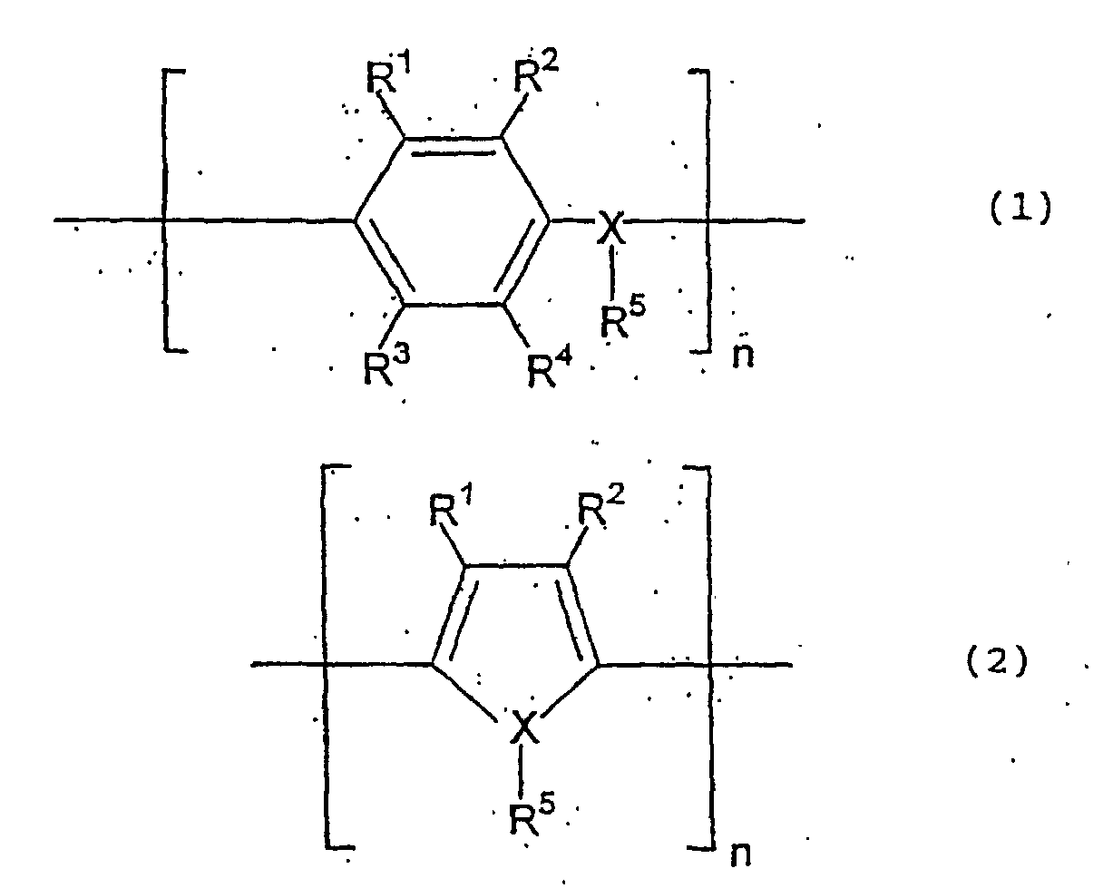
- organic semiconductor there can be mentioned an organic semiconductor containing benzopyrroline tetramer and chrolanyl, an organic semiconductor predominantly comprising tetrathiotetracene, an organic semiconductor predominantly comprising tetracyanoquinodimethane, and an organic semiconductor predominantly comprising a conductive polymer, which is a polymer represented by the following formula (1) or (2) and has been doped with a dopant.
- organic semiconductor there can be mentioned an inorganic semiconductor predominantly comprising lead dioxide or manganese dioxide, and an inorganic semiconductor comprising triiron tetroxide. These semiconductors may be used either alone or as combination of two or more thereof.
- R 1 to R 4 independently represent a hydrogen atom, a C 1 -C 6 alkyl group or a C 1 -C 6 alkoxy group;
- X represents an oxygen, sulfur or nitrogen atom;
- R 5 which is present only when X is a nitrogen atom, represents a hydrogen atom or a C 1 -C 6 alkyl group; and
- R 1 may be bonded together with R 2 , and R 3 may be bonded together with R 4 , to form a cyclic structure.
- polyaniline polyoxyphenylene
- polyphenylene sulfide polythiophene
- polyfuran polypyrrole
- polymethylpyrrole polymethylpyrrole
- the impedance of the produced capacitor further decreases and the capacitance of the capacitor may be further increased at high frequency.
- the other electrode When the other electrode is in solid form, carbon paste and silver paste may be successively formed on the other electrode and encapsulated with a material such as an epoxy resin, to thereby fabricate a capacitor.
- the capacitor may have a niobium or tantalum lead, which has been sintered together with the niobium sintered body or welded to the sintered body after sintering.
- the capacitor comprising the above-described electrodes and the dielectric may be placed in a can which is electrically connected to the other electrode for the fabrication of a capacitor.
- the electrode of the niobium sintered body is led to the outside via the above-described niobium or tantalum lead, and the lead is insulated from the can by a material such as insulating rubber.
- a sintered body having low specific leakage current index obtained according to the present invention, may be used for producing a capacitor having low leakage current and high reliability.
- Characteristics of a niobium powder, a sintered body and a capacitor were determined by the following methods.
- Potassium fluoroniobate (20 g) which had been thoroughly dried at 80°C in vacuum, and sodium (amount by mol of ten times that of potassium fluoroniobate) were placed in a nickel crucible, and the mixture was allowed to react for reduction at 1,000°C for 20 hours under an argon atmosphere. After the completion of reaction, the reaction mixture was cooled, and the thus-reduced product was sequentially washed with water, 95% sulfuric acid, and water, and then dried in vacuum. The dried product was pulverized by a ball mill having an alumina pot and silica-alumina balls contained therein for 40 hours.
- the pulverized product was immersed in a mixture of 50% nitric acid and 10% aqueous hydrogen peroxide (3 : 2 by weight) with stirring so as to remove an impurity introduced during pulverization.
- the thus-treated product was thoroughly washed with water such that the pH of wash liquid reached 7, and dried in vacuum, to thereby obtain a niobium powder having a mean particle diameter of 2.6 ⁇ m.
- the niobium powder was allowed to stand in a vessel filled with nitrogen for two hours at temperatures shown in Table 1, to thereby induce nitridation. Measured nitrogen contents are shown in Table 1.
- each of the nitrided niobium powders was shaped together with a niobium wire (0.3 mm ⁇ ) into a compact having approximate dimensions of 0.3 cm ⁇ 0.18 cm ⁇ 0.45 cm (approximately 0.1 g).
- the compact was allowed to stand in vacuum of 3 ⁇ 10 -5 Torr at 1,300°C for 30 minutes, to thereby produce a sintered body thereof.
- the sintered body was electrochemically converted through application of 20 V in a 0.1% aqueous solution of phosphoric acid at 80°C for 200 minutes, to thereby form a niobium oxide dielectric layer on a surface of the sintered body.
- a niobium rod (20 mm ⁇ , 20 g) was placed in a reactor made of SUS 304. After the reactor was degassed to attain vacuum (approximately 6 ⁇ 10 -4 Torr), the temperature of the reactor was elevated to 800°C, and hydrogen was fed into the reactor. Hydrogen was further introduced at 350°C for 50 hours. After cooling, a hydrogenated niobium ingot was pulverized for 10 hours in a one-liter pot made of SUS 304 and containing iron balls. The pulverized product was placed into the above-described reactor made of SUS 304, and hydrogenated under the same conditions as mentioned above.
- the thus-formed hydrogenated product was mixed with water, to prepare a 20 vol.% slurry, which was pulverized with zirconia balls by a wet-crusher made of SUS 304 (trade name, Attriter).
- the pulverizing time was varied as shown in Table 1, to thereby produce a plurality of niobium powders having different mean particle diameters.
- Each of the niobium powders was sequentially washed with 95% sulfuric acid, water, a mixture of 30% hydrofluoric acid and 50% nitric acid (1 : 1 by weight), and water, and dried in vacuum, to thereby remove an impurity introduced during pulverization.
- Nitridation, shaping, and sintering were carried out in the same manner as described in Example 1 or 2, or Comparative Example 1, to thereby produce sintered bodies.
- sintering was carried out at 1,200°C.
- Conditions for nitridation and the measured nitrogen contents are shown in Table 1.
- the measured capacitance, LC, and specific leakage current index are also shown in Table 1.
- Example 1 to 3 and Comparative Examples 1 to 3 were repeated in Examples 12 to 14 and Comparative Examples 7 to 9, respectively, to thereby prepare 50 sintered bodies for each of the working examples.
- Each of the sintered bodies was electrochemically converted at 20 V in a 0.1% aqueous solution of phosphoric acid for 200 minutes, to thereby form a dielectric niobium oxide film on the surface of the sintered body.
- the thus-treated sintered body was immersed in an aqueous solution of manganese nitrate and heated at 220°C for 30 minutes. This immersion-heating procedure was repeated, to thereby form on the dielectric niobium oxide film a manganese dioxide layer as the other electrode.
- a carbon layer and a silver paste layer were successively formed on the manganese dioxide layer.
- a lead frame was placed on the thus -produced element, and the entirety of the element was encapsulated with an epoxy resin, to thereby produce a chip capacitor.
- Capacitance and LC value of capacitor are shown in Table 3. The LC value was measured after 6.3 V was imposed for one minute at room temperature.
- This immersion-heating procedure was repeated, to thereby form on the dielectric niobium oxide film a layer comprising a lead dioxide-lead sulfate mixture (lead dioxide content of 94 wt.%), serving as the other electrode.
- a carbon layer and a silver paste layer were successively formed on the lead dioxide-lead sulfate mixture layer.
- a lead frame was placed on the thus-produced element, and the entirety thereof was encapsulated with an epoxy resin, to thereby produce a chip capacitor.
- Capacitance and LC value of capacitor are shown in Table 3. The LC value was measured after 6.3 V was imposed for one minute at room temperature.
- Ex. 7 890 18.9 210
- Example 12 330 1.0 212
- Example 13 220 0.9 208
- Example 14 340 1.1 205 Com.
- Ex. 10 870 15.0 151
- a sintered body produced by sintering the niobium powder of the present invention has a reduced specific LC index, and a capacitor produced from the sintered body has good leakage current characteristics and serves as a highly reliable capacitor.
Landscapes
- Chemical & Material Sciences (AREA)
- Engineering & Computer Science (AREA)
- Materials Engineering (AREA)
- Mechanical Engineering (AREA)
- Metallurgy (AREA)
- Organic Chemistry (AREA)
- Power Engineering (AREA)
- Microelectronics & Electronic Packaging (AREA)
- Powder Metallurgy (AREA)
- Ceramic Capacitors (AREA)
- Compositions Of Oxide Ceramics (AREA)
- Physical Or Chemical Processes And Apparatus (AREA)
Abstract
Description

| Content of impurity element [wt. ppm] | ||||||||
| Fe | Ni | Co | Si | Na | K | Mg | Total | |
| Com. Ex. 1 | 50 | 50 | 20 | 60 | 20 | 50 | 20 | 270 |
| Example 1 | 50 | 50 | 20 | 60 | 20 | 50 | 20 | 270 |
| Example 2 | 50 | 50 | 20 | 60 | 20 | 50 | 20 | 270 |
| Example 3 | 50 | 50 | 20 | 60 | 20 | 50 | 20 | 270 |
| Com. Ex. 2 | 50 | 50 | 20 | 60 | 20 | 50 | 20 | 270 |
| Com. Ex. 3 | 50 | 50 | 20 | 60 | 20 | 50 | 20 | 270 |
| Com. Ex. 4 | 20 | 20 | 15 | 30 | 5 | 5 | 5 | 100 |
| Com. Ex. 5 | 20 | 20 | 15 | 30 | 5 | 5 | 5 | 100 |
| Com. Ex. 6 | 20 | 20 | 15 | 30 | 5 | 5 | 5 | 100 |
| Example 4 | 20 | 20 | 20 | 30 | 5 | 5 | 5 | 105 |
| Example 5 | 20 | 20 | 20 | 30 | 5 | 5 | 5 | 105 |
| Example 6 | 20 | 20 | 20 | 30 | 5 | 5 | 5 | 105 |
| Example 7 | 20 | 20 | 20 | 30 | 5 | 5 | 5 | 105 |
| Example 8 | 20 | 20 | 20 | 30 | 5 | 5 | 5 | 105 |
| Example 9 | 20 | 20 | 20 | 30 | 5 | 5 | 5 | 105 |
| Example 10 | 30 | 30 | 20 | 30 | 5 | 5 | 5 | 125 |
| Example 11 | 35 | 35 | 20 | 30 | 5 | 5 | 5 | 135 |
| Sintered body | Capacitor chip | ||
| Specific LC index [pA/(µF·V)] | LC [µA] | Capacitance [µF] | |
| Com. Ex. 7 | 890 | 18.9 | 210 |
| Example 12 | 330 | 1.0 | 212 |
| Example 13 | 220 | 0.9 | 208 |
| Example 14 | 340 | 1.1 | 205 |
| Com. Ex. 8 | 680 | 17.6 | 218 |
| Com. Ex. 9 | 1,130 | 34.2 | 206 |
| Com. Ex. 10 | 870 | 15.0 | 151 |
| Example 15 | 220 | 1.6 | 411 |
| Example 16 | 170 | 2.3 | 526 |
| Example 17 | 150 | 3.5 | 809 |
Claims (10)
- A niobium powder characterized by having a nitrogen content of at least 500 ppm by weight and not more than 7,000 ppm by weight, and having a mean particle diameter of at least 0.2 µm and less than 3 µm.
- The niobium powder as claimed in claim 1, which has a mean particle diameter of at least 0.5 µm and less than 2 µm.
- The niobium powder as claimed in claim 1 or claim 2, which has a nitrogen content of at least 1,000 ppm by weight and not more than 3,000 ppm by weight.
- The niobium powder as claimed in any one of claim 1 to claim 3, which contains at least one element selected from iron, nickel, cobalt, silicon, sodium, potassium and magnesium in an amount such that each element is not more than 100 ppm by weight, or the total amount of the elements is not more than 350 ppm by weight.
- A sintered body produced from a niobium powder,
characterized by having a specific leakage current index of not more than 400 [pA/(µF·V)]. - A sintered body which is produced by sintering the niobium powder as claimed in any one of claim 1 to claim 4.
- The sintered body as claimed in claim 6, which has a specific leakage current index of not more than 400 [pA/(µF·V)].
- The sintered body as claimed in claim 6, which has a specific leakage current index of not more than 200 [pA/(µF·V)].
- A capacitor comprising (i) an electrode, which is the sintered body as claimed in any one of claim 5 to claim 8, (ii) a dielectric formed on a surface of the sintered body, and (iii) a counter electrode.
- The capacitor as claimed in claim 9, wherein said dielectric is composed of niobium oxide formed by electrolytic oxidation on the surface of the niobium sintered body.
Applications Claiming Priority (3)
| Application Number | Priority Date | Filing Date | Title |
|---|---|---|---|
| JP20105899 | 1999-07-15 | ||
| JP20105899 | 1999-07-15 | ||
| PCT/JP2000/004753 WO2001006525A1 (en) | 1999-07-15 | 2000-07-14 | Niobium powder, its sintered body, and capacitor comprising the same |
Publications (3)
| Publication Number | Publication Date |
|---|---|
| EP1204126A1 true EP1204126A1 (en) | 2002-05-08 |
| EP1204126A4 EP1204126A4 (en) | 2003-05-07 |
| EP1204126B1 EP1204126B1 (en) | 2005-09-14 |
Family
ID=16434696
Family Applications (1)
| Application Number | Title | Priority Date | Filing Date |
|---|---|---|---|
| EP00946343A Expired - Lifetime EP1204126B1 (en) | 1999-07-15 | 2000-07-14 | Niobium powder, its sintered body, and capacitor comprising the same |
Country Status (9)
| Country | Link |
|---|---|
| EP (1) | EP1204126B1 (en) |
| JP (1) | JP4527332B2 (en) |
| KR (1) | KR100799634B1 (en) |
| CN (1) | CN1221994C (en) |
| AT (1) | ATE304734T1 (en) |
| AU (1) | AU6017200A (en) |
| DE (1) | DE60022655T2 (en) |
| TW (1) | TW464889B (en) |
| WO (1) | WO2001006525A1 (en) |
Cited By (4)
| Publication number | Priority date | Publication date | Assignee | Title |
|---|---|---|---|---|
| WO2002092864A3 (en) * | 2001-05-15 | 2003-09-25 | Showa Denko Kk | Niobium powder, niobium sintered body and capacitor using the sintered body |
| US7737066B2 (en) | 2001-05-15 | 2010-06-15 | Showa Denko K.K. | Niobium monoxide powder, niobium monoxide sintered body and capacitor using the sintered body |
| EP2221839B2 (en) † | 2000-08-10 | 2017-05-24 | Showa Denko K.K. | Niobium powder, sintered body and capacitor using the body |
| US10329644B2 (en) | 2014-09-11 | 2019-06-25 | Ishihara Chemical Co., Ltd. | Ta—Nb alloy powder and anode element for solid electrolytic capacitor |
Families Citing this family (10)
| Publication number | Priority date | Publication date | Assignee | Title |
|---|---|---|---|---|
| DE19953946A1 (en) * | 1999-11-09 | 2001-05-10 | Starck H C Gmbh Co Kg | Capacitor powder |
| GB2359081A (en) | 2000-02-11 | 2001-08-15 | Astrazeneca Uk Ltd | Pharmaceutically active thiazolopyrimidines |
| CN100491022C (en) | 2000-03-01 | 2009-05-27 | 卡伯特公司 | Nitrided electron tube metals and processes for making same |
| US7274552B2 (en) * | 2001-03-16 | 2007-09-25 | Showa Denko K.K. | Niobium for capacitor and capacitor using sintered body of the niobium |
| AU2008200187B2 (en) * | 2001-05-15 | 2010-02-18 | Showa Denko K.K. | Niobium powder, niobium sintered body and capacitor using the sintered body |
| WO2005045860A1 (en) | 2003-11-10 | 2005-05-19 | Showa Denko K.K. | Niobium powder for capacitor, niobium sintered body and capacitor |
| CN1825509B (en) * | 2005-02-23 | 2011-04-06 | 三洋电机株式会社 | Solid electrolytic capacitor and manufacturing method thereof |
| JP4969233B2 (en) * | 2006-12-20 | 2012-07-04 | 三洋電機株式会社 | Solid electrolytic capacitor and niobium anode lead manufacturing method for solid electrolytic capacitor |
| CN100528418C (en) * | 2008-01-11 | 2009-08-19 | 宁夏东方钽业股份有限公司 | Nitrogen-containing homogeneous valve metal powder and manufacturing method thereof, valve metal blank block and valve metal sintered body and anode of polarized capacitor |
| KR101102872B1 (en) * | 2009-07-17 | 2012-01-09 | 충남대학교산학협력단 | Method for preparing nano tantalum powder using auto combustion |
Family Cites Families (5)
| Publication number | Priority date | Publication date | Assignee | Title |
|---|---|---|---|---|
| JPH01167206A (en) * | 1987-12-22 | 1989-06-30 | Kobe Steel Ltd | Production of niobium nitride |
| JPH10133791A (en) * | 1996-10-28 | 1998-05-22 | Victor Co Of Japan Ltd | Optical radio transmission device, interface, and portable information terminal |
| JP3254163B2 (en) | 1997-02-28 | 2002-02-04 | 昭和電工株式会社 | Capacitor |
| JP3233084B2 (en) * | 1997-11-06 | 2001-11-26 | 日本電気株式会社 | Method for manufacturing anode body of solid electrolytic capacitor |
| JP3196832B2 (en) * | 1998-05-15 | 2001-08-06 | 日本電気株式会社 | Solid electrolytic capacitor and method of manufacturing the same |
-
2000
- 2000-07-14 AU AU60172/00A patent/AU6017200A/en not_active Abandoned
- 2000-07-14 WO PCT/JP2000/004753 patent/WO2001006525A1/en not_active Ceased
- 2000-07-14 EP EP00946343A patent/EP1204126B1/en not_active Expired - Lifetime
- 2000-07-14 DE DE60022655T patent/DE60022655T2/en not_active Expired - Lifetime
- 2000-07-14 KR KR1020027000512A patent/KR100799634B1/en not_active Expired - Fee Related
- 2000-07-14 CN CNB008104247A patent/CN1221994C/en not_active Expired - Fee Related
- 2000-07-14 AT AT00946343T patent/ATE304734T1/en not_active IP Right Cessation
- 2000-07-14 TW TW089114142A patent/TW464889B/en not_active IP Right Cessation
- 2000-07-14 JP JP2001511699A patent/JP4527332B2/en not_active Expired - Fee Related
Non-Patent Citations (2)
| Title |
|---|
| No further relevant documents disclosed * |
| See also references of WO0106525A1 * |
Cited By (9)
| Publication number | Priority date | Publication date | Assignee | Title |
|---|---|---|---|---|
| EP2221839B2 (en) † | 2000-08-10 | 2017-05-24 | Showa Denko K.K. | Niobium powder, sintered body and capacitor using the body |
| WO2002092864A3 (en) * | 2001-05-15 | 2003-09-25 | Showa Denko Kk | Niobium powder, niobium sintered body and capacitor using the sintered body |
| US6934146B2 (en) | 2001-05-15 | 2005-08-23 | Showa Denko K.K. | Niobium powder, niobium sintered body and capacitor using the sintered body |
| EP1388870A4 (en) * | 2001-05-15 | 2006-07-26 | Showa Denko Kk | NIOBIUM MONOXIDE POWDER, SINTERED NIOBIUM MONOXIDE PRODUCT AND CAPACITOR USING THE SINTERED NIOBIUM MONOXIDE PRODUCT |
| AU2002307722B2 (en) * | 2001-05-15 | 2007-10-18 | Showa Denko K.K. | Niobium powder, niobium sintered body and capacitor using the sintered body |
| US7374596B2 (en) | 2001-05-15 | 2008-05-20 | Showa Denko K.K. | Niobium powder, niobium sintered body and capacitor using the sintered body |
| US7737066B2 (en) | 2001-05-15 | 2010-06-15 | Showa Denko K.K. | Niobium monoxide powder, niobium monoxide sintered body and capacitor using the sintered body |
| US7986508B2 (en) | 2001-05-15 | 2011-07-26 | Showa Denko K.K. | Niobium monoxide powder, niobium monoxide sintered body and capacitor using the sintered body |
| US10329644B2 (en) | 2014-09-11 | 2019-06-25 | Ishihara Chemical Co., Ltd. | Ta—Nb alloy powder and anode element for solid electrolytic capacitor |
Also Published As
| Publication number | Publication date |
|---|---|
| AU6017200A (en) | 2001-02-05 |
| KR100799634B1 (en) | 2008-01-30 |
| ATE304734T1 (en) | 2005-09-15 |
| DE60022655T2 (en) | 2006-06-29 |
| CN1221994C (en) | 2005-10-05 |
| EP1204126B1 (en) | 2005-09-14 |
| EP1204126A4 (en) | 2003-05-07 |
| KR20020016891A (en) | 2002-03-06 |
| DE60022655D1 (en) | 2005-10-20 |
| CN1363102A (en) | 2002-08-07 |
| JP4527332B2 (en) | 2010-08-18 |
| WO2001006525A1 (en) | 2001-01-25 |
| TW464889B (en) | 2001-11-21 |
Similar Documents
| Publication | Publication Date | Title |
|---|---|---|
| JP4592034B2 (en) | Niobium powder, niobium sintered body, capacitor using the sintered body, and method for manufacturing the capacitor | |
| EP1204126B1 (en) | Niobium powder, its sintered body, and capacitor comprising the same | |
| EP1275125B1 (en) | Niobium sintered body, production method therefor, and capacitor using the same | |
| EP2221839B2 (en) | Niobium powder, sintered body and capacitor using the body | |
| JPWO2001006525A1 (en) | Niobium powder, its sintered body and capacitor using the same | |
| EP1340235B1 (en) | Powder for capacitor, sintered body thereof and capacitor using the sintered body | |
| US6960237B2 (en) | Niobium powder, sintered body thereof and capacitor using the same | |
| EP1275124B1 (en) | Niobium powder for capacitor, sintered body thereof and capacitor using the sintered body | |
| AU2002218510A1 (en) | Powder for capacitor, sintered body thereof and capacitor using the sintered body | |
| US20030179538A1 (en) | Capacitor | |
| US6643120B2 (en) | Niobium powder for capacitor, sintered body using the powder and capacitor using the same | |
| JP4683512B2 (en) | Capacitor powder, sintered body using the same, and capacitor using the same | |
| US6600646B1 (en) | Niobium powder, sintered body thereof and capacitor using same | |
| JP4422258B2 (en) | Capacitor | |
| EP1281460B1 (en) | Niobium powder, sintered compact thereof and capacitor | |
| EP1918950A2 (en) | Powdered niobium, sintered body thereof, capacitor using the sintered body and production method of the capacitor | |
| JP4707164B2 (en) | Niobium powder for capacitor, sintered body using the same, and capacitor using the same | |
| JPWO2001081029A1 (en) | Niobium powder, its sintered body and capacitor | |
| KR100804652B1 (en) | Niobium powder, sintered body and capacitor |
Legal Events
| Date | Code | Title | Description |
|---|---|---|---|
| PUAI | Public reference made under article 153(3) epc to a published international application that has entered the european phase |
Free format text: ORIGINAL CODE: 0009012 |
|
| 17P | Request for examination filed |
Effective date: 20020129 |
|
| AK | Designated contracting states |
Kind code of ref document: A1 Designated state(s): AT BE CH CY DE DK ES FI FR GB GR IE IT LI LU MC NL PT SE |
|
| AX | Request for extension of the european patent |
Free format text: AL;LT;LV;MK;RO;SI |
|
| A4 | Supplementary search report drawn up and despatched |
Effective date: 20030324 |
|
| RIC1 | Information provided on ipc code assigned before grant |
Ipc: 7C 22C 1/04 B Ipc: 7B 22F 1/00 B Ipc: 7C 22C 32/00 B Ipc: 7C 22C 27/02 B Ipc: 7H 01G 9/042 A |
|
| 17Q | First examination report despatched |
Effective date: 20030620 |
|
| GRAP | Despatch of communication of intention to grant a patent |
Free format text: ORIGINAL CODE: EPIDOSNIGR1 |
|
| GRAS | Grant fee paid |
Free format text: ORIGINAL CODE: EPIDOSNIGR3 |
|
| GRAA | (expected) grant |
Free format text: ORIGINAL CODE: 0009210 |
|
| AK | Designated contracting states |
Kind code of ref document: B1 Designated state(s): AT BE CH CY DE DK ES FI FR GB GR IE IT LI LU MC NL PT SE |
|
| PG25 | Lapsed in a contracting state [announced via postgrant information from national office to epo] |
Ref country code: CH Free format text: LAPSE BECAUSE OF FAILURE TO SUBMIT A TRANSLATION OF THE DESCRIPTION OR TO PAY THE FEE WITHIN THE PRESCRIBED TIME-LIMIT Effective date: 20050914 Ref country code: IT Free format text: LAPSE BECAUSE OF FAILURE TO SUBMIT A TRANSLATION OF THE DESCRIPTION OR TO PAY THE FEE WITHIN THE PRESCRIBED TIME-LIMIT;WARNING: LAPSES OF ITALIAN PATENTS WITH EFFECTIVE DATE BEFORE 2007 MAY HAVE OCCURRED AT ANY TIME BEFORE 2007. THE CORRECT EFFECTIVE DATE MAY BE DIFFERENT FROM THE ONE RECORDED. Effective date: 20050914 Ref country code: LI Free format text: LAPSE BECAUSE OF FAILURE TO SUBMIT A TRANSLATION OF THE DESCRIPTION OR TO PAY THE FEE WITHIN THE PRESCRIBED TIME-LIMIT Effective date: 20050914 Ref country code: BE Free format text: LAPSE BECAUSE OF FAILURE TO SUBMIT A TRANSLATION OF THE DESCRIPTION OR TO PAY THE FEE WITHIN THE PRESCRIBED TIME-LIMIT Effective date: 20050914 Ref country code: AT Free format text: LAPSE BECAUSE OF FAILURE TO SUBMIT A TRANSLATION OF THE DESCRIPTION OR TO PAY THE FEE WITHIN THE PRESCRIBED TIME-LIMIT Effective date: 20050914 Ref country code: FI Free format text: LAPSE BECAUSE OF FAILURE TO SUBMIT A TRANSLATION OF THE DESCRIPTION OR TO PAY THE FEE WITHIN THE PRESCRIBED TIME-LIMIT Effective date: 20050914 Ref country code: NL Free format text: LAPSE BECAUSE OF FAILURE TO SUBMIT A TRANSLATION OF THE DESCRIPTION OR TO PAY THE FEE WITHIN THE PRESCRIBED TIME-LIMIT Effective date: 20050914 |
|
| REG | Reference to a national code |
Ref country code: GB Ref legal event code: FG4D |
|
| REG | Reference to a national code |
Ref country code: CH Ref legal event code: EP |
|
| REG | Reference to a national code |
Ref country code: IE Ref legal event code: FG4D |
|
| REF | Corresponds to: |
Ref document number: 60022655 Country of ref document: DE Date of ref document: 20051020 Kind code of ref document: P |
|
| PG25 | Lapsed in a contracting state [announced via postgrant information from national office to epo] |
Ref country code: SE Free format text: LAPSE BECAUSE OF FAILURE TO SUBMIT A TRANSLATION OF THE DESCRIPTION OR TO PAY THE FEE WITHIN THE PRESCRIBED TIME-LIMIT Effective date: 20051214 Ref country code: DK Free format text: LAPSE BECAUSE OF FAILURE TO SUBMIT A TRANSLATION OF THE DESCRIPTION OR TO PAY THE FEE WITHIN THE PRESCRIBED TIME-LIMIT Effective date: 20051214 Ref country code: GR Free format text: LAPSE BECAUSE OF FAILURE TO SUBMIT A TRANSLATION OF THE DESCRIPTION OR TO PAY THE FEE WITHIN THE PRESCRIBED TIME-LIMIT Effective date: 20051214 |
|
| PG25 | Lapsed in a contracting state [announced via postgrant information from national office to epo] |
Ref country code: ES Free format text: LAPSE BECAUSE OF FAILURE TO SUBMIT A TRANSLATION OF THE DESCRIPTION OR TO PAY THE FEE WITHIN THE PRESCRIBED TIME-LIMIT Effective date: 20051225 |
|
| PG25 | Lapsed in a contracting state [announced via postgrant information from national office to epo] |
Ref country code: PT Free format text: LAPSE BECAUSE OF FAILURE TO SUBMIT A TRANSLATION OF THE DESCRIPTION OR TO PAY THE FEE WITHIN THE PRESCRIBED TIME-LIMIT Effective date: 20060214 |
|
| NLV1 | Nl: lapsed or annulled due to failure to fulfill the requirements of art. 29p and 29m of the patents act | ||
| REG | Reference to a national code |
Ref country code: CH Ref legal event code: PL |
|
| ET | Fr: translation filed | ||
| PG25 | Lapsed in a contracting state [announced via postgrant information from national office to epo] |
Ref country code: IE Free format text: LAPSE BECAUSE OF NON-PAYMENT OF DUE FEES Effective date: 20060714 |
|
| PLBE | No opposition filed within time limit |
Free format text: ORIGINAL CODE: 0009261 |
|
| STAA | Information on the status of an ep patent application or granted ep patent |
Free format text: STATUS: NO OPPOSITION FILED WITHIN TIME LIMIT |
|
| PG25 | Lapsed in a contracting state [announced via postgrant information from national office to epo] |
Ref country code: MC Free format text: LAPSE BECAUSE OF NON-PAYMENT OF DUE FEES Effective date: 20060731 |
|
| 26N | No opposition filed |
Effective date: 20060615 |
|
| REG | Reference to a national code |
Ref country code: IE Ref legal event code: MM4A |
|
| PG25 | Lapsed in a contracting state [announced via postgrant information from national office to epo] |
Ref country code: LU Free format text: LAPSE BECAUSE OF NON-PAYMENT OF DUE FEES Effective date: 20060714 |
|
| PG25 | Lapsed in a contracting state [announced via postgrant information from national office to epo] |
Ref country code: CY Free format text: LAPSE BECAUSE OF FAILURE TO SUBMIT A TRANSLATION OF THE DESCRIPTION OR TO PAY THE FEE WITHIN THE PRESCRIBED TIME-LIMIT Effective date: 20050914 |
|
| PGFP | Annual fee paid to national office [announced via postgrant information from national office to epo] |
Ref country code: FR Payment date: 20080718 Year of fee payment: 9 |
|
| PGFP | Annual fee paid to national office [announced via postgrant information from national office to epo] |
Ref country code: GB Payment date: 20080716 Year of fee payment: 9 |
|
| GBPC | Gb: european patent ceased through non-payment of renewal fee |
Effective date: 20090714 |
|
| REG | Reference to a national code |
Ref country code: FR Ref legal event code: ST Effective date: 20100331 |
|
| PG25 | Lapsed in a contracting state [announced via postgrant information from national office to epo] |
Ref country code: FR Free format text: LAPSE BECAUSE OF NON-PAYMENT OF DUE FEES Effective date: 20090731 |
|
| PG25 | Lapsed in a contracting state [announced via postgrant information from national office to epo] |
Ref country code: GB Free format text: LAPSE BECAUSE OF NON-PAYMENT OF DUE FEES Effective date: 20090714 |
|
| PGFP | Annual fee paid to national office [announced via postgrant information from national office to epo] |
Ref country code: DE Payment date: 20180703 Year of fee payment: 19 |
|
| REG | Reference to a national code |
Ref country code: DE Ref legal event code: R119 Ref document number: 60022655 Country of ref document: DE |
|
| PG25 | Lapsed in a contracting state [announced via postgrant information from national office to epo] |
Ref country code: DE Free format text: LAPSE BECAUSE OF NON-PAYMENT OF DUE FEES Effective date: 20200201 |