EP1204116A1 - Disc player, for instance a CD player - Google Patents
Disc player, for instance a CD player Download PDFInfo
- Publication number
- EP1204116A1 EP1204116A1 EP00403061A EP00403061A EP1204116A1 EP 1204116 A1 EP1204116 A1 EP 1204116A1 EP 00403061 A EP00403061 A EP 00403061A EP 00403061 A EP00403061 A EP 00403061A EP 1204116 A1 EP1204116 A1 EP 1204116A1
- Authority
- EP
- European Patent Office
- Prior art keywords
- disc
- instantaneous period
- player
- disc player
- period
- Prior art date
- Legal status (The legal status is an assumption and is not a legal conclusion. Google has not performed a legal analysis and makes no representation as to the accuracy of the status listed.)
- Withdrawn
Links
- 230000003287 optical effect Effects 0.000 description 1
- 230000002207 retinal effect Effects 0.000 description 1
Images

Classifications
-
- G—PHYSICS
- G11—INFORMATION STORAGE
- G11B—INFORMATION STORAGE BASED ON RELATIVE MOVEMENT BETWEEN RECORD CARRIER AND TRANSDUCER
- G11B17/00—Guiding record carriers not specifically of filamentary or web form, or of supports therefor
- G11B17/02—Details
- G11B17/04—Feeding or guiding single record carrier to or from transducer unit
- G11B17/05—Feeding or guiding single record carrier to or from transducer unit specially adapted for discs not contained within cartridges
-
- G—PHYSICS
- G11—INFORMATION STORAGE
- G11B—INFORMATION STORAGE BASED ON RELATIVE MOVEMENT BETWEEN RECORD CARRIER AND TRANSDUCER
- G11B23/00—Record carriers not specific to the method of recording or reproducing; Accessories, e.g. containers, specially adapted for co-operation with the recording or reproducing apparatus ; Intermediate mediums; Apparatus or processes specially adapted for their manufacture
- G11B23/38—Visual features other than those contained in record tracks or represented by sprocket holes the visual signals being auxiliary signals
- G11B23/40—Identifying or analogous means applied to or incorporated in the record carrier and not intended for visual display simultaneously with the playing-back of the record carrier, e.g. label, leader, photograph
-
- G—PHYSICS
- G11—INFORMATION STORAGE
- G11B—INFORMATION STORAGE BASED ON RELATIVE MOVEMENT BETWEEN RECORD CARRIER AND TRANSDUCER
- G11B33/00—Constructional parts, details or accessories not provided for in the other groups of this subclass
- G11B33/10—Indicating arrangements; Warning arrangements
-
- G—PHYSICS
- G11—INFORMATION STORAGE
- G11B—INFORMATION STORAGE BASED ON RELATIVE MOVEMENT BETWEEN RECORD CARRIER AND TRANSDUCER
- G11B33/00—Constructional parts, details or accessories not provided for in the other groups of this subclass
- G11B33/02—Cabinets; Cases; Stands; Disposition of apparatus therein or thereon
- G11B33/027—Covers
Definitions
- the invention relates to a disc player, for instance a CD player.
- the player In order to read the various tracks of a disc, the player conventionally comprises rotating means for the disc, at a speed of more than 60 rpm.
- This basic compulsory feature has the inherent drawback that, under normal (i.e. constant) lighting conditions, it is not possible for the human eye to view the surface of the disc, for instance a drawing on the disc itself or a label with information, directly or through a transparent cover.
- the invention proposes to allow the disc to be viewed in various positions, for instance to make it easier to be read by the user or to make it possible to have access to the whole surface of the disc through a window not covering the whole surface of the disc.
- the invention proposes a disc player comprising means for rotating a disc with a first instantaneous period, a stroboscope light source able to illuminate at least partly a surface of the disc with a second instantaneous period and means allowing the second instantaneous period to be different from an integer times the first instantaneous period.
- a compact disc (CD) player 2 is represented at figure 1.
- the player 2 comprises a deck 6 and a movable cover 4.
- the cover 4 When in its raised position, the cover 4 allows to put a disc 10 on a reading unit 24 (see figure 2) mounted in the deck 6.
- the reading unit comprises a turntable and an optical pick-up to read information from the disc 10.
- the cover 4 When in its closed position, the cover 4 covers the whole surface of the disc 10.
- the cover 4 comprises a transparent window 8 covering only a part of the surface of the cover 4.
- a disc 10 lies on the reading unit 24, a part of its upper surface carrying a label can thus be seen through the window 8.
- the player 2 comprises control keys : a "play” key 16, a “stop” key 18, a "previous track” key 20 and a “next track” key 22.
- a pressure arm 12 which is attached to the cover 4 allows to press the disc 10 against the turntable of the reading unit 24.
- the outside periphery of the pressure arm 12 defines two protrusions 28 above the disc 10.
- a stroboscope light source 14 is fixed on the pressure arm 12 and located between the two protrusions 28.
- the two protrusions 28 define between them a shape 26 for reflecting at least part of the light it receives from the stroboscope light source 14 to the surface of the disc 10.
- the shape 26 can for instance be part of a paraboloid which focus is located on the stroboscope light source 14 and which axis is directed towards the disc 10.
- the turntable drives the disc 10 into rotation with a first instantaneous period T 1 which is monitored by the servo-control of the player 2.
- the linear velocity of the disc 10 is substantially constant (between 1.2 and 1.4 m/s).
- the rotational instantaneous period T 1 thus varies between about 30 ms and about 300 ms depending on the position of the track which is read on the disc.
- the disc 10 is illuminated every n rotations of the disc, each time n. ⁇ .T 1 2 /(2 ⁇ ) seconds later.
- the rotational speed of the disc is 2 ⁇ /T 1
- the position of the disc will have changed by n. ⁇ .T 1 .
- the position of the disc when illuminated varies by about ⁇ rad/s.
- the parameter ⁇ in the above equation represents the apparent rotation of disc.
- n allows to keep the stroboscope light frequency between about 3 Hz and 10 Hz. These values are sufficient to have an impression of smooth apparent rotation of the disc and at the same time they remain below the limit of retinal persistency (about 30 Hz).
- the above calculation can be implemented in a micro-processor of the player 2, receiving the value for T 1 from the servo-control and controlling the stroboscope light source 14 accordingly.
- the whole surface of the disc 10 can be read though the window 8 only covers a part of the cover 4.
- the value of ⁇ (or more generally the difference between T 2 and T 1 ) can be controlled by the user, for instance through appropriate control keys.
- ⁇ can for instance be variable between 0 rad/s (where the disc looks immobile) and a strictly positive upper limit, for instance 0.5 rad/s. It could also be variable between a strictly negative lower limit ( e . g . - 0.3 rad/s) and a positive upper limit ( e . g . 0.3 rad/s).
- Reference 102 is a disc (CD) player comprising a deck 106 and a cover 104 with a transparent window 108.
- a pressure arm 112 carries a stroboscope light source 114 in the vicinity of the part of the deck 106 receiving the disc. The stroboscope light source 114 thus illuminates the upper surface of the disc situated below the window 108.
- the deck carries control keys : a "play” key 116, a “stop” key 118, a “fast backward” key 120, a “fast forward” key 122, a "look left” key 130 and a “look right” key 132.
- a micro-processor 134 of the player 102 receives information about the rotational period T 1 of the disc from the servo-control unit 136. Depending on this information and on actions from the user on the the "look left” and “look right” control keys 130, 132, the micro-processor 134 will control the stroboscope light source 114 with the period T 2 given according to the below table. "Look left” key "Look right” key T 2 Released Released T 1 Pressed Pressed Pressed Pressed Released T 1 - ⁇ .T 1 2 /(2 ⁇ ) Released Pressed T 1 + ⁇ .T 1 2 /(2 ⁇ )
- the stroboscope light source 114 is lit at the same frequency as the disc rotates : the disc consequently looks immobile.
- the period T 2 of the stroboscope light is a little bit shorter than the rotational period T 1 of the disc : the disc is lit ⁇ .T 1 2 /(2 ⁇ ) seconds before having its position where it was lit at the preceding rotation.
- the disc will thus apparently rotate at a speed of ⁇ rad/s, but this time opposite the actual rotation direction of the disc : the disc will look as if it were turning clockwise.
- the disc When the "look right" key 132 alone is pressed, the disc is lit a little later every rotation : it looks as if it were turning slowly in the actual rotation direction of the disc ( i . e . anticlockwise seen from the top), as explained in relation with the first embodiment.
- This solution allows the user to choose which part of the disc surface he wants to see beneath the window 108. For instance, this can be convenient to read titles of songs written on a given part of the disc label. By releasing the "look right” or “look left” key, the user gets a still image of the disc surface.
- the value of T 2 can be changed automatically (and not depending on controls from the user any more): T 2 could repeatedly be equal to T 1 + ⁇ .T 1 2 /(2 ⁇ ) during 1 second and equal to T 1 during 10 seconds. The disc would then look as if it were turning of an angle ⁇ (during 1 second) every 11 seconds (it would look as still during the remaining 10 seconds).
- the deck 16, 116 shows no mechanism beneath the window 8, 108 to keep an aesthetic looking when no disc is loaded in the player 2, 102.
- the window 8, 108 covers substantially the whole surface of the disc 10.
- the invention allows to view the disc surface in a reading position (at least from time to time in the first embodiment) which was not for sure in the prior art where the disc label could be (and stayed) upside down.
- a disc recorder is considered as a kind of disc player in the sense of an apparatus which can use a disc.
Landscapes
- Optical Recording Or Reproduction (AREA)
Abstract
A disc player (2) comprises means for rotating a disc (10) with a first
instantaneous period and a stroboscope light source (14) able to illuminate at
least partly a surface of the disc (10), for instance below a window (8) of a
cover (4), with a second instantaneous period.
The second instantaneous period can be made different from an
integer times the first instantaneous period.
Description
- The invention relates to a disc player, for instance a CD player.
- In order to read the various tracks of a disc, the player conventionally comprises rotating means for the disc, at a speed of more than 60 rpm. This basic compulsory feature has the inherent drawback that, under normal (i.e. constant) lighting conditions, it is not possible for the human eye to view the surface of the disc, for instance a drawing on the disc itself or a label with information, directly or through a transparent cover.
- To avoid this drawback, it has been proposed as described in EP 0 177 107 A1 to illuminate the surface of the disc with a stroboscope which period equals the rotation period of the rotating means. The disc is thus illuminated at the same position on each rotation which makes it possible for the human eye to view the words, symbols or drawings on the surface of the disc as the disc looks immobile.
- Countrarily to these teachings, the invention proposes to allow the disc to be viewed in various positions, for instance to make it easier to be read by the user or to make it possible to have access to the whole surface of the disc through a window not covering the whole surface of the disc.
- In this goal, the invention proposes a disc player comprising means for rotating a disc with a first instantaneous period, a stroboscope light source able to illuminate at least partly a surface of the disc with a second instantaneous period and means allowing the second instantaneous period to be different from an integer times the first instantaneous period.
- According to preferred features :
- the stroboscope light source is fixed on a pressure arm ;
- the pressure arm defines at least a reflection shape in front of said stroboscope light source;
- the difference between the second instantaneous period and an integer times the first instantaneous period is proportional to the square of the first instantaneous period ;
- the second instantaneous period is constantly different from an integer times the first instantaneous period ;
- the second instantaneous period is different from an integer times the first instantaneous period when a control key is pressed ;
- the second instantaneous period is periodically different from an integer times the first instantaneous period for a given lapse of time ;
- a transparent window covers only a part of a cover of the disc player.
- The invention and other features thereof will be understood in the light of the following description made with reference to the attached drawings
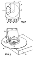
where : - figure 1 represents a top view of a first embodiment of a disc player according to the invention ;
- figure 2 represents a perspective view of some of the elements of the disc player of figure 1 ;
- figure 3 represents a top view of a second embodiment of a disc player according to the invention ;
- figure 4 represents some of the electronic circuits of the disc player of figure 3.
- A compact disc (CD) player 2 is represented at figure 1. The player 2 comprises a deck 6 and a movable cover 4. When in its raised position, the cover 4 allows to put a disc 10 on a reading unit 24 (see figure 2) mounted in the deck 6. The reading unit comprises a turntable and an optical pick-up to read information from the disc 10. When in its closed position, the cover 4 covers the whole surface of the disc 10.
- The cover 4 comprises a transparent window 8 covering only a part of the surface of the cover 4. When a disc 10 lies on the reading unit 24, a part of its upper surface carrying a label can thus be seen through the window 8.
- The player 2 comprises control keys : a "play" key 16, a "stop" key 18, a "previous track" key 20 and a "next track" key 22.
- On figure 2, some elements of the player 2 are represented : a pressure arm 12 which is attached to the cover 4 allows to press the disc 10 against the turntable of the reading unit 24. The outside periphery of the pressure arm 12 defines two protrusions 28 above the disc 10. A stroboscope light source 14 is fixed on the pressure arm 12 and located between the two protrusions 28.
- The two protrusions 28 define between them a shape 26 for reflecting at least part of the light it receives from the stroboscope light source 14 to the surface of the disc 10. The shape 26 can for instance be part of a paraboloid which focus is located on the stroboscope light source 14 and which axis is directed towards the disc 10.
- The turntable drives the disc 10 into rotation with a first instantaneous period T1 which is monitored by the servo-control of the player 2. The linear velocity of the disc 10 is substantially constant (between 1.2 and 1.4 m/s). The rotational instantaneous period T1 thus varies between about 30 ms and about 300 ms depending on the position of the track which is read on the disc.
- The stroboscope light source 14 is lit with a second instantaneous period T2 which is determined as a function of the first instantaneous period T1 according to the formula :
- n = 3 when T1 is below 100 ms,
- n = 1 when T1 is above 100 ms.
-
- In this way, the disc 10 is illuminated every n rotations of the disc, each time n.Φ.T1 2/(2π) seconds later. As the rotational speed of the disc is 2π/T1, each time the light is lit, the position of the disc will have changed by n.Φ.T1. As the light is lit about n.T1 times a second (Φ.T1 2/(2π) is very small compared to T,), the position of the disc when illuminated varies by about Φ rad/s. This means that the parameter Φ in the above equation represents the apparent rotation of disc. Φ has a non-null fixed value. For instance, Φ = 0.15 rad/s can be used. The disc thus seems to rotate slowly, realising an apparent rotation (2π rad) in about 20 seconds.
- It is to be noted that the use of the parameter n allows to keep the stroboscope light frequency between about 3 Hz and 10 Hz. These values are sufficient to have an impression of smooth apparent rotation of the disc and at the same time they remain below the limit of retinal persistency (about 30 Hz).
- The above calculation can be implemented in a micro-processor of the player 2, receiving the value for T1 from the servo-control and controlling the stroboscope light source 14 accordingly.
- Thanks to this solution, the whole surface of the disc 10 can be read though the window 8 only covers a part of the cover 4.
- According to a possible variation, the value of Φ (or more generally the difference between T2 and T1) can be controlled by the user, for instance through appropriate control keys. According to this variation, Φ can for instance be variable between 0 rad/s (where the disc looks immobile) and a strictly positive upper limit, for instance 0.5 rad/s. It could also be variable between a strictly negative lower limit (e.g. - 0.3 rad/s) and a positive upper limit (e.g. 0.3 rad/s).
- Another embodiment of the invention is represented at figures 3 and 4. Reference 102 is a disc (CD) player comprising a deck 106 and a cover 104 with a transparent window 108. A pressure arm 112 carries a stroboscope light source 114 in the vicinity of the part of the deck 106 receiving the disc. The stroboscope light source 114 thus illuminates the upper surface of the disc situated below the window 108.
- The deck carries control keys : a "play" key 116, a "stop" key 118, a "fast backward" key 120, a "fast forward" key 122, a "look left" key 130 and a "look right" key 132.
- The use of the "look left" key 130 and of the "look right" key 132 will now be explained with reference to figure 4.
- A micro-processor 134 of the player 102 receives information about the rotational period T1 of the disc from the servo-control unit 136. Depending on this information and on actions from the user on the the "look left" and "look right" control keys 130, 132, the micro-processor 134 will control the stroboscope light source 114 with the period T2 given according to the below table.
"Look left" key "Look right" key T2 Released Released T1 Pressed Pressed Pressed Released T1 - Φ.T1 2/(2π) Released Pressed T1 + Φ.T1 2/(2π) - In this way, when none (or both, which should not happen theoretically) of the "look left" and "look right" keys is (are) pressed, the stroboscope light source 114 is lit at the same frequency as the disc rotates : the disc consequently looks immobile.
- When the "look left" key 130 is pressed (while the "look right" key 132 in not pressed), the period T2 of the stroboscope light is a little bit shorter than the rotational period T1 of the disc : the disc is lit Φ.T1 2/(2π) seconds before having its position where it was lit at the preceding rotation. As explained above, the disc will thus apparently rotate at a speed of Φ rad/s, but this time opposite the actual rotation direction of the disc : the disc will look as if it were turning clockwise.
- When the "look right" key 132 alone is pressed, the disc is lit a little later every rotation : it looks as if it were turning slowly in the actual rotation direction of the disc (i.e. anticlockwise seen from the top), as explained in relation with the first embodiment.
- This solution allows the user to choose which part of the disc surface he wants to see beneath the window 108. For instance, this can be convenient to read titles of songs written on a given part of the disc label. By releasing the "look right" or "look left" key, the user gets a still image of the disc surface.
- According to another possible embodiment, the value of T2 can be changed automatically (and not depending on controls from the user any more): T2 could repeatedly be equal to T1 + Φ.T1 2/(2π) during 1 second and equal to T1 during 10 seconds. The disc would then look as if it were turning of an angle Φ (during 1 second) every 11 seconds (it would look as still during the remaining 10 seconds).
- Preferably, the deck 16, 116 shows no mechanism beneath the window 8, 108 to keep an aesthetic looking when no disc is loaded in the player 2, 102.
- According to a possible variation, the window 8, 108 covers substantially the whole surface of the disc 10. In this case, the invention allows to view the disc surface in a reading position (at least from time to time in the first embodiment) which was not for sure in the prior art where the disc label could be (and stayed) upside down.
- For this invention, a disc recorder is considered as a kind of disc player in the sense of an apparatus which can use a disc.
Claims (8)
- Disc player (2 ; 102) comprising :characterised bymeans (24) for rotating a disc (10 ; 110) with a first instantaneous period ;a stroboscope light source (14 ; 114) able to illuminate at least partly a surface of the disc (10 ; 110) with a second instantaneous period,means (130, 132, 134) allowing the second instantaneous period to be different from an integer times the first instantaneous period.
- Disc player according to claim 1, wherein the stroboscope light source (114) is fixed on a pressure arm (12 ; 112).
- Disc player according to claim 2, wherein the pressure arm (12) defines at least a reflection shape (26) in front of said stroboscope light source (14).
- Disc player according to any of the preceding claims, wherein the difference between the second instantaneous period and an integer times the first instantaneous period is proportional to the square of the first instantaneous period.
- Disc player according to any of claims 1 to 3, wherein the second instantaneous period is constantly different from an integer times the first instantaneous period.
- Disc player according to any of claims 1 to 3, wherein the second instantaneous period is different from an integer times the first instantaneous period when a control key (130, 132) is pressed.
- Disc player according to any of claims 1 to 3, wherein the second instantaneous period is periodically different from an integer times the first instantaneous period for a given lapse of time.
- Disc player according to any of the preceding claims, wherein a transparent window (8 ; 108) covers only a part of a cover (4 ; 104) of the disc player.
Priority Applications (1)
| Application Number | Priority Date | Filing Date | Title |
|---|---|---|---|
| EP00403061A EP1204116A1 (en) | 2000-11-03 | 2000-11-03 | Disc player, for instance a CD player |
Applications Claiming Priority (1)
| Application Number | Priority Date | Filing Date | Title |
|---|---|---|---|
| EP00403061A EP1204116A1 (en) | 2000-11-03 | 2000-11-03 | Disc player, for instance a CD player |
Publications (1)
| Publication Number | Publication Date |
|---|---|
| EP1204116A1 true EP1204116A1 (en) | 2002-05-08 |
Family
ID=8173932
Family Applications (1)
| Application Number | Title | Priority Date | Filing Date |
|---|---|---|---|
| EP00403061A Withdrawn EP1204116A1 (en) | 2000-11-03 | 2000-11-03 | Disc player, for instance a CD player |
Country Status (1)
| Country | Link |
|---|---|
| EP (1) | EP1204116A1 (en) |
Citations (7)
| Publication number | Priority date | Publication date | Assignee | Title |
|---|---|---|---|---|
| DE3330229A1 (en) * | 1982-12-15 | 1984-01-12 | Alps Electric Co., Ltd., Tokyo | Laser-beam disc playback device |
| JPS5919283A (en) * | 1982-07-20 | 1984-01-31 | Akai Electric Co Ltd | Disk player |
| JPS5940349A (en) * | 1982-08-30 | 1984-03-06 | Hitachi Ltd | Digital audio player |
| EP0159090A1 (en) * | 1984-04-17 | 1985-10-23 | Koninklijke Philips Electronics N.V. | Equipment which enables the words inscribed on a compact disc to be read while the disc is being played |
| JPS6282589A (en) * | 1985-10-07 | 1987-04-16 | Matsushita Electric Ind Co Ltd | Lighting system for disc regenerator |
| US4706237A (en) * | 1984-10-05 | 1987-11-10 | U.S. Philips Corporation | Disc player with strobe light illumination |
| JPH0319186A (en) * | 1989-06-16 | 1991-01-28 | Sanyo Electric Co Ltd | Optical disk player |
-
2000
- 2000-11-03 EP EP00403061A patent/EP1204116A1/en not_active Withdrawn
Patent Citations (7)
| Publication number | Priority date | Publication date | Assignee | Title |
|---|---|---|---|---|
| JPS5919283A (en) * | 1982-07-20 | 1984-01-31 | Akai Electric Co Ltd | Disk player |
| JPS5940349A (en) * | 1982-08-30 | 1984-03-06 | Hitachi Ltd | Digital audio player |
| DE3330229A1 (en) * | 1982-12-15 | 1984-01-12 | Alps Electric Co., Ltd., Tokyo | Laser-beam disc playback device |
| EP0159090A1 (en) * | 1984-04-17 | 1985-10-23 | Koninklijke Philips Electronics N.V. | Equipment which enables the words inscribed on a compact disc to be read while the disc is being played |
| US4706237A (en) * | 1984-10-05 | 1987-11-10 | U.S. Philips Corporation | Disc player with strobe light illumination |
| JPS6282589A (en) * | 1985-10-07 | 1987-04-16 | Matsushita Electric Ind Co Ltd | Lighting system for disc regenerator |
| JPH0319186A (en) * | 1989-06-16 | 1991-01-28 | Sanyo Electric Co Ltd | Optical disk player |
Non-Patent Citations (4)
| Title |
|---|
| PATENT ABSTRACTS OF JAPAN vol. 008, no. 109 (P - 275) 22 May 1984 (1984-05-22) * |
| PATENT ABSTRACTS OF JAPAN vol. 008, no. 141 (P - 283) 30 June 1984 (1984-06-30) * |
| PATENT ABSTRACTS OF JAPAN vol. 011, no. 287 (P - 617) 17 September 1987 (1987-09-17) * |
| PATENT ABSTRACTS OF JAPAN vol. 015, no. 144 (P - 1189) 11 April 1991 (1991-04-11) * |
Similar Documents
| Publication | Publication Date | Title |
|---|---|---|
| MY116366A (en) | Disc player apparatus | |
| EP0363056A3 (en) | Compact disk player | |
| CA2011534C (en) | Disc changer | |
| CA2277742A1 (en) | Disc library apparatus | |
| US4196906A (en) | Video disc player | |
| US6128265A (en) | Portable disc player | |
| US4216969A (en) | Carriage translating apparatus for video disc player | |
| JPH0679413B2 (en) | Disk Engineer Device | |
| EP0268723B1 (en) | Electronically controlled televisual music stand | |
| CA1138566A (en) | Video disc player | |
| JP3322326B2 (en) | Carousel optical disk drive | |
| JPS5919283A (en) | Disk player | |
| JP2679691B2 (en) | Disc player | |
| BE904978A (en) | ||
| JPH07334911A (en) | Disk player | |
| KR100281879B1 (en) | Portable computer | |
| KR100240124B1 (en) | Top-loading CD | |
| KR100294877B1 (en) | Portable computer | |
| JPH0727714B2 (en) | Lighting equipment for disc regenerator | |
| JPS5822253Y2 (en) | record player | |
| JP3518595B2 (en) | Disc changer device | |
| JP2545430Y2 (en) | Disk unit | |
| JP2835509B2 (en) | Disk cleaner device | |
| JPS5824264Y2 (en) | optical recording or reproducing device | |
| JPH01184753A (en) | disc loading device |
Legal Events
| Date | Code | Title | Description |
|---|---|---|---|
| PUAI | Public reference made under article 153(3) epc to a published international application that has entered the european phase |
Free format text: ORIGINAL CODE: 0009012 |
|
| AK | Designated contracting states |
Kind code of ref document: A1 Designated state(s): AT BE CH CY DE DK ES FI FR GB GR IE IT LI LU MC NL PT SE TR |
|
| AX | Request for extension of the european patent |
Free format text: AL;LT;LV;MK;RO;SI |
|
| AKX | Designation fees paid | ||
| REG | Reference to a national code |
Ref country code: DE Ref legal event code: 8566 |
|
| STAA | Information on the status of an ep patent application or granted ep patent |
Free format text: STATUS: THE APPLICATION IS DEEMED TO BE WITHDRAWN |
|
| 18D | Application deemed to be withdrawn |
Effective date: 20021109 |