EP1204020A2 - Method and apparatus for implementing anti-counterfeiting measures in personal computer-based digital color printers - Google Patents
Method and apparatus for implementing anti-counterfeiting measures in personal computer-based digital color printers Download PDFInfo
- Publication number
- EP1204020A2 EP1204020A2 EP01126045A EP01126045A EP1204020A2 EP 1204020 A2 EP1204020 A2 EP 1204020A2 EP 01126045 A EP01126045 A EP 01126045A EP 01126045 A EP01126045 A EP 01126045A EP 1204020 A2 EP1204020 A2 EP 1204020A2
- Authority
- EP
- European Patent Office
- Prior art keywords
- printer
- host processor
- image representation
- print data
- electronic image
- Prior art date
- Legal status (The legal status is an assumption and is not a legal conclusion. Google has not performed a legal analysis and makes no representation as to the accuracy of the status listed.)
- Ceased
Links
Images


Classifications
-
- G—PHYSICS
- G06—COMPUTING OR CALCULATING; COUNTING
- G06F—ELECTRIC DIGITAL DATA PROCESSING
- G06F21/00—Security arrangements for protecting computers, components thereof, programs or data against unauthorised activity
- G06F21/60—Protecting data
- G06F21/606—Protecting data by securing the transmission between two devices or processes
- G06F21/608—Secure printing
-
- G—PHYSICS
- G06—COMPUTING OR CALCULATING; COUNTING
- G06F—ELECTRIC DIGITAL DATA PROCESSING
- G06F3/00—Input arrangements for transferring data to be processed into a form capable of being handled by the computer; Output arrangements for transferring data from processing unit to output unit, e.g. interface arrangements
- G06F3/12—Digital output to print unit, e.g. line printer, chain printer
- G06F3/1201—Dedicated interfaces to print systems
- G06F3/1202—Dedicated interfaces to print systems specifically adapted to achieve a particular effect
- G06F3/1222—Increasing security of the print job
-
- G—PHYSICS
- G06—COMPUTING OR CALCULATING; COUNTING
- G06F—ELECTRIC DIGITAL DATA PROCESSING
- G06F3/00—Input arrangements for transferring data to be processed into a form capable of being handled by the computer; Output arrangements for transferring data from processing unit to output unit, e.g. interface arrangements
- G06F3/12—Digital output to print unit, e.g. line printer, chain printer
- G06F3/1201—Dedicated interfaces to print systems
- G06F3/1223—Dedicated interfaces to print systems specifically adapted to use a particular technique
- G06F3/1237—Print job management
- G06F3/1244—Job translation or job parsing, e.g. page banding
-
- G—PHYSICS
- G06—COMPUTING OR CALCULATING; COUNTING
- G06F—ELECTRIC DIGITAL DATA PROCESSING
- G06F3/00—Input arrangements for transferring data to be processed into a form capable of being handled by the computer; Output arrangements for transferring data from processing unit to output unit, e.g. interface arrangements
- G06F3/12—Digital output to print unit, e.g. line printer, chain printer
- G06F3/1201—Dedicated interfaces to print systems
- G06F3/1278—Dedicated interfaces to print systems specifically adapted to adopt a particular infrastructure
- G06F3/1284—Local printer device
-
- G—PHYSICS
- G06—COMPUTING OR CALCULATING; COUNTING
- G06F—ELECTRIC DIGITAL DATA PROCESSING
- G06F3/00—Input arrangements for transferring data to be processed into a form capable of being handled by the computer; Output arrangements for transferring data from processing unit to output unit, e.g. interface arrangements
- G06F3/12—Digital output to print unit, e.g. line printer, chain printer
- G06F3/1201—Dedicated interfaces to print systems
- G06F3/1202—Dedicated interfaces to print systems specifically adapted to achieve a particular effect
- G06F3/1211—Improving printing performance
-
- G—PHYSICS
- G06—COMPUTING OR CALCULATING; COUNTING
- G06F—ELECTRIC DIGITAL DATA PROCESSING
- G06F3/00—Input arrangements for transferring data to be processed into a form capable of being handled by the computer; Output arrangements for transferring data from processing unit to output unit, e.g. interface arrangements
- G06F3/12—Digital output to print unit, e.g. line printer, chain printer
- G06F3/1201—Dedicated interfaces to print systems
- G06F3/1202—Dedicated interfaces to print systems specifically adapted to achieve a particular effect
- G06F3/1218—Reducing or saving of used resources, e.g. avoiding waste of consumables or improving usage of hardware resources
- G06F3/122—Reducing or saving of used resources, e.g. avoiding waste of consumables or improving usage of hardware resources with regard to computing resources, e.g. memory, CPU
-
- G—PHYSICS
- G06—COMPUTING OR CALCULATING; COUNTING
- G06F—ELECTRIC DIGITAL DATA PROCESSING
- G06F3/00—Input arrangements for transferring data to be processed into a form capable of being handled by the computer; Output arrangements for transferring data from processing unit to output unit, e.g. interface arrangements
- G06F3/12—Digital output to print unit, e.g. line printer, chain printer
- G06F3/1201—Dedicated interfaces to print systems
- G06F3/1223—Dedicated interfaces to print systems specifically adapted to use a particular technique
- G06F3/1237—Print job management
- G06F3/1267—Job repository, e.g. non-scheduled jobs, delay printing
Definitions
- the present invention relates to the digital color printer art. It finds particular application in conjunction with a method and apparatus for implementing anti-counterfeiting measures in personal computer-based digital color printers, and will be described with particular reference thereto. However, it should be appreciated that the present invention may also find application in conjunction with other types of digital color marking systems and applications where anti-counterfeiting measures are implemented.
- Electrophotographic marking is performed by exposing an image representation of a desired document onto a substantially uniformly charged photoreceptor. In response to the image representation, the photoreceptor discharges so as to create an electrostatic latent image of the desired document on the photoreceptor's surface. Toner particles are then deposited onto the latent image so as to form a toner image. The toner image is then transferred from the photoreceptor onto a substrate such as a sheet of paper. The transferred toner image is then fused to the substrate, usually using heat and/or pressure. The surface of the photoreceptor is then cleaned of residual developing material and recharged in preparation for the production of another image. Electrophotographic marking can be used to produce color images by repeating the above process once for each color of toner that is used to make the composite color image.
- Low-end marking devices typically do not include a large amount of on-board memory or processing capability.
- a system for rendering an electronic image representation associated with a software application program includes a host processor programmed to execute the software application program; a temporary storage device associated with the host processor; a printer interfaced to the host processor; and a software program operative on the host processor for determining whether the electronic image representation is of a predetermined document type by examining at least a portion of the electronic image representation when stored in the temporary storage device during the course of printing the electronic image representation at the printer.
- a system for detecting an image representation of a predetermined document type includes a host processor; a temporary storage device associated with the host processor; a printer interfaced to the host processor; and software means operative on the host processor for a) buffering print data associated with a first portion of the image representation in the temporary storage device; b) examining the buffered print data for a preselected feature of the predetermined document type; c) rendering at least a portion of the buffered print data on the printer when the preselected feature is not found in the buffered print data; and d) not rendering the buffered print data when the preselected feature is found in the buffered print data.
- a method for detecting a preselected feature of an electronic image representation in a system including a host processor, a temporary storage device associated with the host processor, and a printer interfaced to the host processor includes a) buffering a first segment of the electronic image representation in the temporary storage device; b) examining the first segment of the electronic image representation for the preselected feature; c) rendering at least a portion of the first segment on the printer when the preselected feature is not found in the first segment; and d) not rendering the first segment when the preselected feature is found in the first segment.
- One advantage of the present invention is the provision of a system for rendering an electronic image representation associated with a software application program that leverages the relatively large memory capacity and processing power of the host processor.
- Another advantage of the present invention is the provision of a system for rendering an electronic image representation associated with a software application program that incorporates or otherwise bundles an anti-counterfeiting detector routine with a printer driver.
- Yet another advantage of the present invention is the provision of a system for rendering an electronic image representation associated with a software application program without disadvantageously increasing the on-board memory capacity and/or processing power of an associated digital color printer.
- Yet another advantage of the present invention is the provision of a system for detecting an image representation of a predetermined document type that leverages the relatively large memory capacity and processing power of the host processor.
- Still another advantage of the present invention is the provision of a system for detecting an image representation of a predetermined document type that incorporates or otherwise bundles an anti-counterfeiting detector routine with a printer driver.
- a still further advantage of the present invention is the provision of a system for detecting an image representation of a predetermined document type without disadvantageously increasing the on-board memory capacity and/or processing power of an associated digital color printer.
- the invention may take form in various components and arrangements of components, and in various steps and arrangements of steps.
- the drawings are only for purposes of illustrating a preferred embodiment and are not to be construed as limiting the invention.
- exemplary computing equipment 20 capable of implementing the present invention includes host processor 23 comprising a personal computer (hereinafter "PC"), preferably an IBM PC-compatible computer having a windowing environment, such as Microsoft.RTM. Windows98.
- host processor 23 comprising a personal computer (hereinafter "PC"), preferably an IBM PC-compatible computer having a windowing environment, such as Microsoft.RTM. Windows98.
- display screen 22 comprising a color monitor or the like
- keyboard 26 for entering text data and user commands
- pointing device 27 preferably comprises a mouse for pointing and for manipulating objects displayed on display screen 22.
- Computing equipment 20 includes a computer-readable memory medium, such as fixed computer disk 25, and floppy disk interface 24.
- Floppy disk interface 24 provides a means whereby computing equipment 20 can access information, such as data, application programs, etc., stored on floppy disks.
- a similar CD-ROM interface (not shown) may be provided with computing equipment 20, through which computing equipment 20 can access information stored on CD-ROMs.
- Disk 25 stores, among other things, application programs by which host processor 23 generates files, manipulates and stores those files on disk 25, presents data in those files to an operator via display screen 22, and prints data in those files via printer 30.
- Disk 25 also stores an operating system which, as noted above, is preferably a windowing operating system such as Windows98.
- Device drivers are also stored in disk 25. At least one of the device drivers comprises a printer driver which provides a software interface to firmware in printer 30. Data exchange between host processor 23 and printer 30 is described in more detail below.
- printer 30 is a multi-head serial printer, such as an ink jet printer. Accordingly, although the invention described herein is not limited to use with such a printer, the invention will be described in the context of a such a printer.
- FIG. 2 is a block diagram showing the internal structures of host processor 23 and printer 30.
- host processor 23 includes a central processing unit 100 such as a programmable microprocessor interfaced to computer bus 101. Also coupled to computer bus 101 are display interface 102 for interfacing to display 22, printer interface 104 for interfacing to printer 30 through bi-directional communication line 106, floppy disk interface 24 for interfacing to floppy disk 107, keyboard interface 109 for interfacing to keyboard 26, and pointing device interface 110 for interfacing to pointing device 27.
- Disk 25 includes an operating system section for storing operating system 111, an applications section for storing applications 112, and a printer driver section for storing printer driver 114.
- RAM 116 interfaces to computer bus 101 to provide CPU 100 with access to memory storage.
- RAM random access main memory
- CPU 100 loads those application instruction sequences from disk 25 (or other storage media such as media accessed via a network or floppy disk drive 24) into random access memory (hereinafter "RAM") 116 and executes those stored program instruction sequences out of RAM 116.
- RAM 116 provides for a print data buffer used by printer driver 114 according to the invention, as described more fully hereinbelow.
- ROM 43 in host processor 23 stores invariant instruction sequences, such as start-up instruction sequences or basic input/output operating system (BIOS) sequences for operation of keyboard 26.
- BIOS basic input/output operating system
- disk 25 stores program instruction sequences for a windowing operating system and for various application programs such as graphics application programs, drawing application programs, desktop publishing application programs, and the like.
- disk 25 also stores color image files such as might be displayed by display 22 or printed by printer 30 under control of a designated application program.
- Disk 25 also stores a color monitor driver in other drivers section 119 which controls how multi-level RGB color primary values are provided to display interface 102.
- Printer driver 114 controls printer 30 for both black and color printing and supplies print data for print out according to the configuration of printer 30. Print data is transferred to printer 30, and control signals are exchanged between host processor 23 and printer 30, through printer interface 104 connected to line 106 under control of printer driver 114.
- Other device drivers are also stored on disk 25, for providing appropriate signals to various devices, such as network devices, facsimile devices, and the like, connected to host processor 23.
- printer 30 includes CPU 121 such as an 8-bit or a 16-bit microprocessor including programmable timer and interrupt controller, ROM 122, control logic 124, and I/O ports unit 127 connected to bus 126. Also connected to control logic 124 is RAM 129. Control logic 124 includes controllers for line feed motor 61, for print image buffer storage in RAM 129, for heat pulse generation, and for head data. Control logic 124 also provides control signals for nozzles in print heads 130a and 130b of print engine 131, carriage motor 66, line feed motor 61, and print data for print heads 130a and 130b, and receives information from print engine 131 for alignment of print heads 130a and 130b through I/O ports unit 127.
- CPU 121 such as an 8-bit or a 16-bit microprocessor including programmable timer and interrupt controller
- ROM 122 read-only memory
- control logic 124 includes controllers for line feed motor 61, for print image buffer storage in RAM 129, for heat pulse generation, and for head data. Control
- EEPROM 132 is connected to I/O ports unit 127 to provide non-volatile memory for printer information such as print head configuration and print head alignment parameters. EEPROM 132 also stores parameters that identify the printer, the driver, the print heads, alignment of the print heads, the status of ink in the cartridges, etc., which are sent to printer driver 114 of host processor 23 to inform host processor 23 of the operational parameters of printer 30.
- I/O ports unit 127 is coupled to print engine 131 in which the pair of print heads 130a and 130b perform recording on a recording medium by scanning across the recording medium while printing using print data from a print buffer in RAM 129.
- Control logic 124 is also coupled to printer interface 104 of host processor 23 via communication line 106 for exchange of control signals and to receive print data and print data addresses.
- ROM 122 stores font data, program instruction sequences used to control printer 30, and other invariant data for printer operation.
- RAM 129 stores print data in a print buffer defined by printer driver 114 for print heads 130a and 130b and other information for printer operation.
- Print heads 130a and 130b of print engine 131 correspond to ink cartridges that are stored in cartridge receptacles (not shown). Sensors generally indicated as 134 are arranged in print engine 131 to detect printer status and to measure temperature and other quantities that affect printing. For instance, a photo sensor in cartridge receptacles measures print density and dot locations for automatic alignment. Sensors 134 are also arranged in print engine 131 to detect other conditions such as the open or closed status of access cover 32 (Fig. 1), presence of recording media, etc. In addition, diode sensors, including a thermistor, are located in print heads 130a and 130b to measure print head temperature, which is transmitted to I/O ports unit 127.
- I/O ports unit 127 also receives input from switches 133 such as a power button and a resume button and delivers control signals to indicator LEDs 135, to buzzer 128, and to line feed motor 61 and carriage motor 66 through line feed motor driver 61a and carriage motor driver 66a, respectively.
- the buzzer 128 may comprise a speaker.
- control logic 124 may be combined with I/O ports 127 in an ASIC to simplify interconnections for the functions of printer 30.
- FIG. 3 shows a high-level functional block diagram that illustrates the interaction between host processor 23 and printer 30.
- operating system 111 issues graphics device interface (GDI) calls to printer driver 114.
- the printer driver 114 is a software program that enables a software application such as image processing application program 112a to access the features of printer 30.
- the application program 112a sets up a print job with formatting commands such as page breaks, font selections, paper tray selections, number of copies, etc.
- the printer driver 114 takes these commands, translates them into a printer language such as Printer Control Language (PCL) or PostScript and then sends the print job to the printer 30.
- PCL Printer Control Language
- the printer driver 114 responds to GDI calls issued from the operating system 111 by generating PCL print data corresponding to the print instructions, and stores the PCL print data in print data store 136. That is, the application program 112a and/or operating system 111 converts the desired print data into GDI or other text commands and graphics primitives with associated page positions and/or forms controls. These commands may be formatted by the printer driver 114 into a recognizable industry defined data definition (e.g. PCL), or the printer driver 114 may use the application program 112a and/or platform intermediate commands (e.g., Microsoft Windows.TM. GDI primitives) and act on these commands to create internal direct printer commands to control the printer 30. Where necessary, the printer driver 114 may also perform additional image processing operations on the PCL data such as color correction, halftoning, etc. before the print job is sent to the printer 30.
- PCL industry defined data definition
- the printer driver 114 may also perform additional image processing operations on the PCL data such as color correction, halftoning,
- Print data store 136 may reside in RAM 116 or in disk 25, or through disk swapping operations of operating system 111 may initially be stored in RAM 116 and swapped in and out of disk 25. Thereafter, printer driver 114 obtains print data from print data store 136 and transmits the print data through printer interface 104, to bidirectional communication line 106, and to print buffer 139 through printer control 140.
- Print buffer 139 resides in RAM 129 and printer control 140 resides in control logic 124 and CPU 121 of Figure 2.
- Printer control 140 processes the print data in print buffer 139 responsive to commands received from host processor 23 and performs printing tasks under control of instructions stored in ROM 122 to provide appropriate print head and other control signals to print engine 131 for recording images onto recording media.
- Print buffer 139 has a first section for storing print data to be printed by one of print heads 130a and 130b, and a second section for storing print data to be printed by the other one of print heads 130a and 130b.
- Each print buffer section has storage locations corresponding to the number of print positions of the associated print head. These storage locations are defined by printer driver 114 according to a resolution selected for printing.
- Each print buffer section also includes additional storage locations for transfer of print data during ramp-up of print heads 130a and 130b to printing speed.
- Print data is transferred from print data store 136 in host processor 23 to storage locations of print buffer 139 that are addressed by printer driver 114. As a result, print data for a next scan may be inserted into vacant storage locations in print buffer 139 both during ramp up and during printing of a current scan.
- PC-side printer driver system One benefit of having a PC-side printer driver system is the movement of the print job processing into the PC itself, rather than at the printer 30, thereby permitting more flexibility and control. Another benefit of this system is that more advanced functions are possible by using a more powerful host PC, while permitting cost minimization of the printer hardware itself (e.g. less memory and processing capability).
- a buffer such as a vacant area of the print data store 136
- preselected image features such as patterns, security marks, icons, seals, etc.
- a band or swath of print data refers or otherwise corresponds to the number of rows of data that can be printed by the printheads 130a, 130b collectively (either aligned or offset along the media feed or x-axis) during a single traverse of a print carriage along the carriage scan or y-axis (perpendicular to the media feed or x-axis) across the print media.
- an exemplary electronic image representation 250 of a paper currency is shown to include a conventional feature 252 such as a pattern, security mark, icon, seal, etc.
- the particular electronic image representation 250 can be entirely recorded (i.e. printed) with eight passes of the printheads 130a, 130b across the print media along the carriage scan or y-axis. Accordingly, the print data generated by the application 112a is divided into eight bands (n) each of which corresponds to a respective swath of the printheads 130a, 130b.
- the anti-counterfeiting detector routine 200 processes the bands of print data according to the following pseudo-code, where N is number of bands or swaths required to print the image representation, M is the number of bands of print data needed to detect a counterfeit image, and n is the current band of print data:
- image processing operations e.g. halftoning
- each counterfeit detection subroutine is designed to detect one or more preselected features such as patterns, security marks, icons, seals, etc. that are embedded in the image data.
- a counterfeit detection subroutine that is specifically designed to detect the image feature 252 would be employed in step 208.
- any known counterfeit detection scheme can be implemented in step 208 (line 11 of pseudo-code).
- Suitable methods for detecting specific features in image representations of counterfeit documents are disclosed in issued U.S. Patent Nos. 5,533,144 and 6,067,374, and in co-pending U.S. patent application Serial No. 09/328,481, filed on June 9, 1999, and assigned to the same assignee of the present invention.
- control advances to step 210 where one or more steps are taken to prevent the complete image representation from being printed at the printer 30.
- the bands of PCL data not yet printed can be corrupted or obliterated in some manner such as by writing over the PCL data with a uniform pixel value or a pattern of pixel values, terminating the printing process, erasing the PCL data, generating an error message, etc.
- FIFO first-in-first-out
- certain image processing operations may affect the ability of the counterfeit detection subroutine (step 208) to detect a counterfeit image
- other image processing operations e.g. color correction
- those image processing operations that do not affect the ability of the counterfeit detection scheme to detect a preselected feature i.e. pattern, security mark, icon, seal, etc.
- those image processing operations that do affect the ability of the counterfeit detection scheme to detect the feature can be performed after (e.g. step 212) the counterfeit detection subroutine has returned a FALSE value.
- the routine 200 ends at step 220.
- the relatively large memory capacity and processing power of the host processor 23 can be leveraged to provide a cost-effective anti-counterfeiting solution for PC-based, digital color printers (e.g. 30) by incorporating (i.e. embedding within) or otherwise bundling an anti-counterfeiting detector routine (e.g. 200) with a printer driver (e.g. 114) without disadvantageously increasing the on-board memory capacity and/or processing power of the digital color printer 30.
Landscapes
- Engineering & Computer Science (AREA)
- Theoretical Computer Science (AREA)
- Physics & Mathematics (AREA)
- General Engineering & Computer Science (AREA)
- General Physics & Mathematics (AREA)
- Human Computer Interaction (AREA)
- Computer Security & Cryptography (AREA)
- Health & Medical Sciences (AREA)
- General Health & Medical Sciences (AREA)
- Computer Hardware Design (AREA)
- Bioethics (AREA)
- Software Systems (AREA)
- Record Information Processing For Printing (AREA)
- Accessory Devices And Overall Control Thereof (AREA)
- Facsimile Image Signal Circuits (AREA)
Abstract
Description
- The present invention relates to the digital color printer art. It finds particular application in conjunction with a method and apparatus for implementing anti-counterfeiting measures in personal computer-based digital color printers, and will be described with particular reference thereto. However, it should be appreciated that the present invention may also find application in conjunction with other types of digital color marking systems and applications where anti-counterfeiting measures are implemented.
- It is known to implement anti-counterfeiting measures in high-end electrophotographic marking devices, such as xerographic copiers, which anti-counterfeiting measures typically require relatively large amounts of on-board memory and processing power. Electrophotographic marking is performed by exposing an image representation of a desired document onto a substantially uniformly charged photoreceptor. In response to the image representation, the photoreceptor discharges so as to create an electrostatic latent image of the desired document on the photoreceptor's surface. Toner particles are then deposited onto the latent image so as to form a toner image. The toner image is then transferred from the photoreceptor onto a substrate such as a sheet of paper. The transferred toner image is then fused to the substrate, usually using heat and/or pressure. The surface of the photoreceptor is then cleaned of residual developing material and recharged in preparation for the production of another image. Electrophotographic marking can be used to produce color images by repeating the above process once for each color of toner that is used to make the composite color image.
- There has been a proliferation of low-end marking devices, such as digital color printers that are primarily used with personal computers (PCS), and that are now capable of generating very high quality color renderings of image representations at a relatively low cost. This has led to a growing concern over the possibility of using such low-end digital color printers for illicitly reproducing or otherwise generating currency, checks, stock certificates, legal documents, and other printed documents that are not legally reproducible. Obviously, any reproductions of these documents are counterfeit and illegal.
- Low-end marking devices typically do not include a large amount of on-board memory or processing capability. Thus, it is not feasible to incorporate the same relatively expensive, hardware intensive, anti-counterfeiting measures found in high-end electrophotographic marking devices into such low-end, PC-based, digital color printers. Accordingly, it is considered desirable to develop a new and improved, low-cost, method and apparatus for implementing anti-counterfeiting measures in PC-based digital color printers, that meets the above-stated needs and overcomes the foregoing difficulties and others while providing better and more advantageous results.
- In accordance with one aspect of the present invention, a system for rendering an electronic image representation associated with a software application program is disclosed. The system includes a host processor programmed to execute the software application program; a temporary storage device associated with the host processor; a printer interfaced to the host processor; and a software program operative on the host processor for determining whether the electronic image representation is of a predetermined document type by examining at least a portion of the electronic image representation when stored in the temporary storage device during the course of printing the electronic image representation at the printer.
- In accordance with another aspect of the present invention, a system for detecting an image representation of a predetermined document type is disclosed. The system includes a host processor; a temporary storage device associated with the host processor; a printer interfaced to the host processor; and software means operative on the host processor for a) buffering print data associated with a first portion of the image representation in the temporary storage device; b) examining the buffered print data for a preselected feature of the predetermined document type; c) rendering at least a portion of the buffered print data on the printer when the preselected feature is not found in the buffered print data; and d) not rendering the buffered print data when the preselected feature is found in the buffered print data.
- In accordance with yet another aspect of the present invention, a method for detecting a preselected feature of an electronic image representation in a system including a host processor, a temporary storage device associated with the host processor, and a printer interfaced to the host processor, is disclosed. The method includes a) buffering a first segment of the electronic image representation in the temporary storage device; b) examining the first segment of the electronic image representation for the preselected feature; c) rendering at least a portion of the first segment on the printer when the preselected feature is not found in the first segment; and d) not rendering the first segment when the preselected feature is found in the first segment.
- One advantage of the present invention is the provision of a system for rendering an electronic image representation associated with a software application program that leverages the relatively large memory capacity and processing power of the host processor.
- Another advantage of the present invention is the provision of a system for rendering an electronic image representation associated with a software application program that incorporates or otherwise bundles an anti-counterfeiting detector routine with a printer driver.
- Yet another advantage of the present invention is the provision of a system for rendering an electronic image representation associated with a software application program without disadvantageously increasing the on-board memory capacity and/or processing power of an associated digital color printer.
- Yet another advantage of the present invention is the provision of a system for detecting an image representation of a predetermined document type that leverages the relatively large memory capacity and processing power of the host processor.
- Still another advantage of the present invention is the provision of a system for detecting an image representation of a predetermined document type that incorporates or otherwise bundles an anti-counterfeiting detector routine with a printer driver.
- A still further advantage of the present invention is the provision of a system for detecting an image representation of a predetermined document type without disadvantageously increasing the on-board memory capacity and/or processing power of an associated digital color printer.
- Still further advantages of the present invention will become apparent to those of ordinary skill in the art upon reading and understanding the following detailed description of the preferred embodiments.
- The invention may take form in various components and arrangements of components, and in various steps and arrangements of steps. The drawings are only for purposes of illustrating a preferred embodiment and are not to be construed as limiting the invention.
- Figure 1 shows a perspective view of exemplary computing equipment including a personal computer (PC) and an digital color printer that are used in connection with the present invention;
- Figure 2 is a block diagram showing a hardware configuration of a host processor interfaced to the printer of Figure 1;
- Figure 3 shows a functional block diagram of the host processor and printer of Figure 1;
- Figure 4 is a flow chart illustrating a method for implementing anti-counterfeiting measures in the computing equipment of Figure 1; and
- Figure 5 is an exemplary image representation capable of being printed by the printer of Figure 1.
-
- Referring now to Figure 1,
exemplary computing equipment 20 capable of implementing the present invention includeshost processor 23 comprising a personal computer (hereinafter "PC"), preferably an IBM PC-compatible computer having a windowing environment, such as Microsoft.RTM. Windows98. Provided withcomputing equipment 20 aredisplay screen 22 comprising a color monitor or the like,keyboard 26 for entering text data and user commands, and pointingdevice 27.Pointing device 27 preferably comprises a mouse for pointing and for manipulating objects displayed ondisplay screen 22. -
Computing equipment 20 includes a computer-readable memory medium, such asfixed computer disk 25, andfloppy disk interface 24.Floppy disk interface 24 provides a means wherebycomputing equipment 20 can access information, such as data, application programs, etc., stored on floppy disks. A similar CD-ROM interface (not shown) may be provided withcomputing equipment 20, through whichcomputing equipment 20 can access information stored on CD-ROMs. Disk 25 stores, among other things, application programs by whichhost processor 23 generates files, manipulates and stores those files ondisk 25, presents data in those files to an operator viadisplay screen 22, and prints data in those files viaprinter 30. Disk 25 also stores an operating system which, as noted above, is preferably a windowing operating system such as Windows98. - Device drivers are also stored in
disk 25. At least one of the device drivers comprises a printer driver which provides a software interface to firmware inprinter 30. Data exchange betweenhost processor 23 andprinter 30 is described in more detail below. - In a preferred embodiment of the invention,
printer 30 is a multi-head serial printer, such as an ink jet printer. Accordingly, although the invention described herein is not limited to use with such a printer, the invention will be described in the context of a such a printer. - Figure 2 is a block diagram showing the internal structures of
host processor 23 andprinter 30. In Figure 2,host processor 23 includes acentral processing unit 100 such as a programmable microprocessor interfaced tocomputer bus 101. Also coupled tocomputer bus 101 aredisplay interface 102 for interfacing to display 22,printer interface 104 for interfacing toprinter 30 through bi-directionalcommunication line 106,floppy disk interface 24 for interfacing tofloppy disk 107,keyboard interface 109 for interfacing tokeyboard 26, and pointingdevice interface 110 for interfacing to pointingdevice 27.Disk 25 includes an operating system section for storingoperating system 111, an applications section for storingapplications 112, and a printer driver section for storingprinter driver 114. - A random access main memory (hereinafter "RAM") 116 interfaces to
computer bus 101 to provideCPU 100 with access to memory storage. In particular, when executing stored application program instruction sequences such as those associated with application programs stored inapplications section 112 ofdisk 25,CPU 100 loads those application instruction sequences from disk 25 (or other storage media such as media accessed via a network or floppy disk drive 24) into random access memory (hereinafter "RAM") 116 and executes those stored program instruction sequences out of RAM 116. RAM 116 provides for a print data buffer used byprinter driver 114 according to the invention, as described more fully hereinbelow. It should also be recognized that standard disk-swapping techniques available under the windowing operating system allow segments of memory, including the aforementioned print data buffer, to be swapped on and off ofdisk 25. Read only memory (hereinafter "ROM") 43 inhost processor 23 stores invariant instruction sequences, such as start-up instruction sequences or basic input/output operating system (BIOS) sequences for operation ofkeyboard 26. - As shown in Figure 2, and as previously mentioned,
disk 25 stores program instruction sequences for a windowing operating system and for various application programs such as graphics application programs, drawing application programs, desktop publishing application programs, and the like. In addition,disk 25 also stores color image files such as might be displayed bydisplay 22 or printed byprinter 30 under control of a designated application program.Disk 25 also stores a color monitor driver inother drivers section 119 which controls how multi-level RGB color primary values are provided to displayinterface 102.Printer driver 114controls printer 30 for both black and color printing and supplies print data for print out according to the configuration ofprinter 30. Print data is transferred toprinter 30, and control signals are exchanged betweenhost processor 23 andprinter 30, throughprinter interface 104 connected toline 106 under control ofprinter driver 114. Other device drivers are also stored ondisk 25, for providing appropriate signals to various devices, such as network devices, facsimile devices, and the like, connected to hostprocessor 23. - Ordinarily, application programs and drivers stored on
disk 25 need first to be installed by the user ontodisk 25 from other computer-readable media on which those programs and drivers are initially stored. For example, it is customary for a user to purchase a floppy disk, or other computer-readable media such as CD-ROM, on which a copy of a printer driver is stored. Such a floppy disk or CD-ROM is also customarily included with the purchase ofprinter 30. The user would then install the printer driver ontodisk 25 through well-known techniques by which the printer driver is copied ontodisk 25. At the same time, it is also possible for the user, via a modem interface (not shown) or via a network (not shown), to download a printer driver, such as by downloading from a file server or from a computerized bulletin board. - With continued reference to Figure 2,
printer 30 includesCPU 121 such as an 8-bit or a 16-bit microprocessor including programmable timer and interrupt controller,ROM 122,control logic 124, and I/O ports unit 127 connected tobus 126. Also connected to controllogic 124 isRAM 129.Control logic 124 includes controllers forline feed motor 61, for print image buffer storage inRAM 129, for heat pulse generation, and for head data.Control logic 124 also provides control signals for nozzles inprint heads print engine 131,carriage motor 66,line feed motor 61, and print data forprint heads print engine 131 for alignment ofprint heads O ports unit 127.EEPROM 132 is connected to I/O ports unit 127 to provide non-volatile memory for printer information such as print head configuration and print head alignment parameters.EEPROM 132 also stores parameters that identify the printer, the driver, the print heads, alignment of the print heads, the status of ink in the cartridges, etc., which are sent toprinter driver 114 ofhost processor 23 to informhost processor 23 of the operational parameters ofprinter 30. - I/
O ports unit 127 is coupled toprint engine 131 in which the pair ofprint heads RAM 129.Control logic 124 is also coupled toprinter interface 104 ofhost processor 23 viacommunication line 106 for exchange of control signals and to receive print data and print data addresses.ROM 122 stores font data, program instruction sequences used to controlprinter 30, and other invariant data for printer operation.RAM 129 stores print data in a print buffer defined byprinter driver 114 forprint heads - Print heads 130a and 130b of
print engine 131 correspond to ink cartridges that are stored in cartridge receptacles (not shown). Sensors generally indicated as 134 are arranged inprint engine 131 to detect printer status and to measure temperature and other quantities that affect printing. For instance, a photo sensor in cartridge receptacles measures print density and dot locations for automatic alignment.Sensors 134 are also arranged inprint engine 131 to detect other conditions such as the open or closed status of access cover 32 (Fig. 1), presence of recording media, etc. In addition, diode sensors, including a thermistor, are located inprint heads O ports unit 127. - I/
O ports unit 127 also receives input fromswitches 133 such as a power button and a resume button and delivers control signals toindicator LEDs 135, tobuzzer 128, and to linefeed motor 61 andcarriage motor 66 through linefeed motor driver 61a and carriage motor driver 66a, respectively. Thebuzzer 128 may comprise a speaker. - Although Figure 2 shows individual components of
printer 30 as separate and distinct from one another, it is preferable that some of the components be combined. For example,control logic 124 may be combined with I/O ports 127 in an ASIC to simplify interconnections for the functions ofprinter 30. - Figure 3 shows a high-level functional block diagram that illustrates the interaction between
host processor 23 andprinter 30. As illustrated in Figure 3, when a print instruction is issued from imageprocessing application program 112a stored inapplication section 112 ofdisk 25,operating system 111 issues graphics device interface (GDI) calls toprinter driver 114. Theprinter driver 114 is a software program that enables a software application such as imageprocessing application program 112a to access the features ofprinter 30. For example, when an image is printed, theapplication program 112a sets up a print job with formatting commands such as page breaks, font selections, paper tray selections, number of copies, etc. Theprinter driver 114 takes these commands, translates them into a printer language such as Printer Control Language (PCL) or PostScript and then sends the print job to theprinter 30. - Thus, the
printer driver 114 responds to GDI calls issued from theoperating system 111 by generating PCL print data corresponding to the print instructions, and stores the PCL print data inprint data store 136. That is, theapplication program 112a and/oroperating system 111 converts the desired print data into GDI or other text commands and graphics primitives with associated page positions and/or forms controls. These commands may be formatted by theprinter driver 114 into a recognizable industry defined data definition (e.g. PCL), or theprinter driver 114 may use theapplication program 112a and/or platform intermediate commands (e.g., Microsoft Windows.TM. GDI primitives) and act on these commands to create internal direct printer commands to control theprinter 30. Where necessary, theprinter driver 114 may also perform additional image processing operations on the PCL data such as color correction, halftoning, etc. before the print job is sent to theprinter 30. -
Print data store 136 may reside in RAM 116 or indisk 25, or through disk swapping operations ofoperating system 111 may initially be stored in RAM 116 and swapped in and out ofdisk 25. Thereafter,printer driver 114 obtains print data fromprint data store 136 and transmits the print data throughprinter interface 104, tobidirectional communication line 106, and to printbuffer 139 throughprinter control 140.Print buffer 139 resides inRAM 129 andprinter control 140 resides incontrol logic 124 andCPU 121 of Figure 2.Printer control 140 processes the print data inprint buffer 139 responsive to commands received fromhost processor 23 and performs printing tasks under control of instructions stored inROM 122 to provide appropriate print head and other control signals toprint engine 131 for recording images onto recording media. -
Print buffer 139 has a first section for storing print data to be printed by one ofprint heads print heads printer driver 114 according to a resolution selected for printing. Each print buffer section also includes additional storage locations for transfer of print data during ramp-up ofprint heads print data store 136 inhost processor 23 to storage locations ofprint buffer 139 that are addressed byprinter driver 114. As a result, print data for a next scan may be inserted into vacant storage locations inprint buffer 139 both during ramp up and during printing of a current scan. - One benefit of having a PC-side printer driver system is the movement of the print job processing into the PC itself, rather than at the
printer 30, thereby permitting more flexibility and control. Another benefit of this system is that more advanced functions are possible by using a more powerful host PC, while permitting cost minimization of the printer hardware itself (e.g. less memory and processing capability). - With reference now to Figure 4, one such advanced function that executes as part of or in association with
printer driver 114 within thePC 23, rather than theprinter 30, is an anti-counterfeiting detector routine 200 (Fig. 5) that i) intercepts PCL data formatted by theprinter driver 114, ii) stores the intercepted PCL data in a buffer such as a vacant area of theprint data store 136, iii) examines the buffered PCL data and recognizes one or more preselected image features such as patterns, security marks, icons, seals, etc. that may be represented in the buffered PCL data, and iv) and corrupts, obliterates, or otherwise ruins the PCL data when such an image feature (indicative of a counterfeit document) is detected. - When images are printed band-by-band (i.e. swath-by-swath), it may be necessary to buffer multiple bands of print data in a temporary memory area such as within the
print data store 136. The actual amount of print data that must be buffered depends on the image context size required to detect the preselected feature(s) (i.e. pattern, security mark, icon, seal, etc.) within a counterfeit image representation. That is, if the size of the preselected feature is greater than the size (i.e. the number of rows) of a single band of print data, then multiple bands of print data must be buffered before the print data can be examined for such a feature. As defined herein, a band or swath of print data refers or otherwise corresponds to the number of rows of data that can be printed by theprintheads - With continued reference to Figure 4, and particular reference to Figure 5, an exemplary
electronic image representation 250 of a paper currency is shown to include aconventional feature 252 such as a pattern, security mark, icon, seal, etc. The particularelectronic image representation 250 can be entirely recorded (i.e. printed) with eight passes of theprintheads application 112a is divided into eight bands (n) each of which corresponds to a respective swath of theprintheads 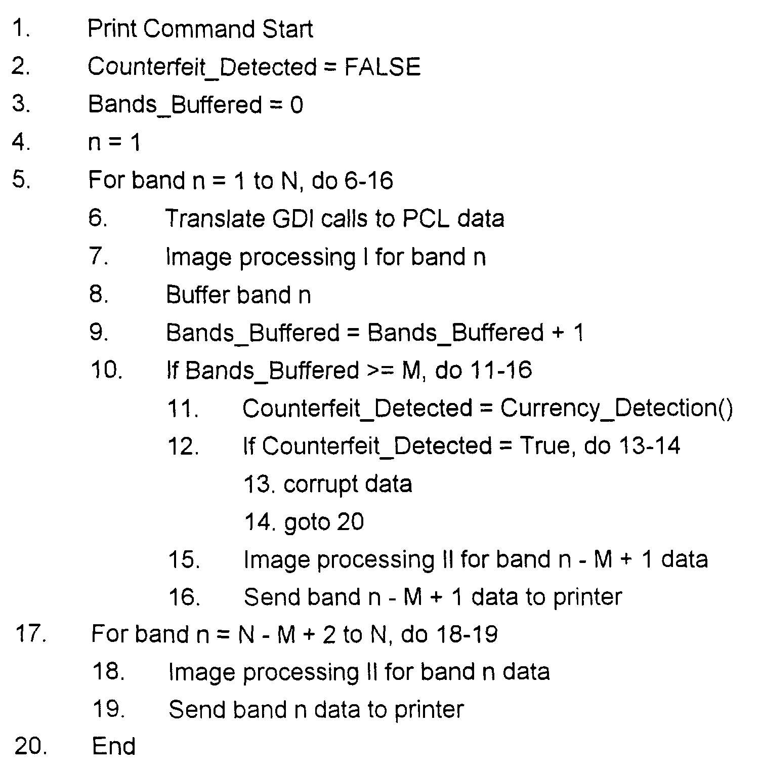
- The anti-counterfeiting detector routine 200 (Fig. 4) starts when a print job is initiated, such as when printing the electronic image representation 250 (step 202). Following an initialization step 204 (lines 2-4 of pseudo-code), a first band of print data (n=1) is processed and buffered (step 206). That is, the band of print data is first translated from GDI calls to PCL data (
line 6 of pseudo-code), and then one or more image processing operations may be performed on the first band of PCL data (line 7 of pseudo-code). For instance, if necessary, a conventional color correction operation can be performed on the first band of PCL data prior to buffering the first band of PCL data in the print data store 136 (line 8 of pseudo-code). It should be noted that certain image processing operations (e.g. halftoning) may correct the PCL data to the point that the printer driver's ability to detect a counterfeit image representation is adversely effected, and should not be performed instep 206. - It is then determined whether there are enough bands of print data buffered in the
print data store 136 to detect the preselected feature 252 (line 10 of pseudo-code). In the case of the paper currency image representation 250 (Fig. 5), three bands of PCL data (M=3) must be buffered in theprint data store 136 in order to detect thefeature 252. If the necessary number (M=3) of PCL data bands are not buffered, then control returns topseudo-code line 5 and the next band of print data (n=2) is processed and buffered (lines 6-9 of pseudo-code). - Once the necessary number (M=3) of PCL bands are processed and buffered, control advances to step 208 where one or more counterfeit detection subroutines are executed. Generally, each counterfeit detection subroutine is designed to detect one or more preselected features such as patterns, security marks, icons, seals, etc. that are embedded in the image data. Thus, a counterfeit detection subroutine that is specifically designed to detect the
image feature 252 would be employed instep 208. - However, it is contemplated that any known counterfeit detection scheme can be implemented in step 208 (line 11 of pseudo-code). Suitable methods for detecting specific features in image representations of counterfeit documents are disclosed in issued U.S. Patent Nos. 5,533,144 and 6,067,374, and in co-pending U.S. patent application Serial No. 09/328,481, filed on June 9, 1999, and assigned to the same assignee of the present invention.
- If the
preselected feature 252 is detected in the currently buffered PCL data, then control advances to step 210 where one or more steps are taken to prevent the complete image representation from being printed at theprinter 30. More particularly, the bands of PCL data not yet printed can be corrupted or obliterated in some manner such as by writing over the PCL data with a uniform pixel value or a pattern of pixel values, terminating the printing process, erasing the PCL data, generating an error message, etc. - If the
preselected feature 252 is not detected in the currently buffered PCL data, then control advances to step 212 where further processing of the oldest band (n=1) of currently buffered PCL data occurs (i.e. further image processing and printing occurs on a first-in-first-out (FIFO) basis)(line 15 of pseudo-code). That is, one or more additional image processing operations can be performed on the oldest band of currently buffered PCL data, prior to sending or otherwise making the oldest band of currently buffered PCL data available to theprinter 30 for printing (line 16 of pseudo-code). For instance, if necessary, a conventional half-toning operation can be performed on the oldest band of currently buffered PCL data prior to being printed. - As indicated above, it should be appreciated that certain image processing operations (e.g. such as half-toning) may affect the ability of the counterfeit detection subroutine (step 208) to detect a counterfeit image, while other image processing operations (e.g. color correction) may have no such effect. Accordingly, those image processing operations that do not affect the ability of the counterfeit detection scheme to detect a preselected feature (i.e. pattern, security mark, icon, seal, etc.) can be performed prior to (e.g. step 206) executing the counterfeit detection subroutine (step 208), while those image processing operations that do affect the ability of the counterfeit detection scheme to detect the feature can be performed after (e.g. step 212) the counterfeit detection subroutine has returned a FALSE value.
- Once the oldest band of currently buffered PCL data is printed, control advances to step 214 to determine if there are additional bands of print data to be processed (e.g. bands 4-8). If so, control advances to step 216 (
line 5 of pseudo-code) where the next band of print data (e.g. n=4) processed and buffered (lines 6-9 of pseudo-code). Thereafter, steps 208-216 are executed to band-wise process and buffer each of the N bands of print data comprising the image representation. - After i) the Nth (e.g. N=8) band of print data has been processed and buffered (lines 6-9 of pseudo-code), ii) the counterfeit detection subroutine has not detected the
preselected feature 252 in the currently buffered PCL data (line 11 of pseudo-code), and iii) the (N - M + 1)th and oldest band of currently buffered PCL data (e.g. 8-3+1=6th) is printed, then control advances to step 218 where the remaining bands of buffered print data (e.g. the 7th and 8th bands) are processed and then printed (lines 17-19 of pseudo-code). Thereafter, the routine 200 ends atstep 220. - Thus, the relatively large memory capacity and processing power of the
host processor 23 can be leveraged to provide a cost-effective anti-counterfeiting solution for PC-based, digital color printers (e.g. 30) by incorporating (i.e. embedding within) or otherwise bundling an anti-counterfeiting detector routine (e.g. 200) with a printer driver (e.g. 114) without disadvantageously increasing the on-board memory capacity and/or processing power of thedigital color printer 30.
Claims (10)
- A system for rendering an electronic image representation associated with a software application program, the system comprising:a host processor (23) programmed to execute the software application program;a temporary storage device (136) associated with the host processor (23);a printer (30) interfaced to the host processor (23); andsoftware means operative on the host processor (23) for determining whether the electronic image representation is of a predetermined document type by examining at least a portion of the electronic image representation when stored in the temporary storage device during the course of printing the electronic image representation at the printer.
- The system of claim 1, wherein the host processor is a personal computer.
- The system of claim 1, wherein the temporary storage device is a plurality of memory addresses allocated in a random access memory of the host processor.
- The system of claim 1, wherein the software means is a printer driver software program.
- The system of claim 1, wherein the predetermined document type is a counterfeit document type.
- The system of claim 1, wherein the electronic image representation is stored and printed on a band-by-band basis.
- The system according to one of the claims 1 to 6, wherein the software means is further operative on the host processor (23) for:a) buffering print data associated with a first portion of the image representation in the temporary storage device (136);b) examining the buffered print data for a preselected feature of the predetermined document type;c) rendering at least a portion of the buffered print data on the printer (30) when the preselected feature is not found in the buffered print data; andd) not rendering the buffered print data when the preselected feature is found in the buffered print data.
- A method for detecting a preselected feature of an electronic image representation in a system including a host processor, a temporary storage device associated with the host processor, and a printer interfaced to the host processor, the method comprising:a) buffering a first segment of the electronic image representation in the temporary storage device;b) examining the first segment of the electronic image representation for the preselected feature;c) rendering at least a portion of the first segment on the printer when the preselected feature is not found in the first segment; andd) not rendering the first segment when the preselected feature is found in the first segment.
- The method of claim 8, further including:prior to b), performing an image processing operation on the first segment.
- The method of claim 8 or 9, further including:prior to c), performing an image processing operation on the portion of the first segment.
Applications Claiming Priority (2)
| Application Number | Priority Date | Filing Date | Title |
|---|---|---|---|
| US09/707,409 US7002704B1 (en) | 2000-11-06 | 2000-11-06 | Method and apparatus for implementing anti-counterfeiting measures in personal computer-based digital color printers |
| US707409 | 2000-11-06 |
Publications (2)
| Publication Number | Publication Date |
|---|---|
| EP1204020A2 true EP1204020A2 (en) | 2002-05-08 |
| EP1204020A3 EP1204020A3 (en) | 2005-12-07 |
Family
ID=24841580
Family Applications (1)
| Application Number | Title | Priority Date | Filing Date |
|---|---|---|---|
| EP01126045A Ceased EP1204020A3 (en) | 2000-11-06 | 2001-10-31 | Method and apparatus for implementing anti-counterfeiting measures in personal computer-based digital color printers |
Country Status (3)
| Country | Link |
|---|---|
| US (1) | US7002704B1 (en) |
| EP (1) | EP1204020A3 (en) |
| JP (1) | JP2002202872A (en) |
Cited By (1)
| Publication number | Priority date | Publication date | Assignee | Title |
|---|---|---|---|---|
| GB2378548A (en) * | 2001-06-04 | 2003-02-12 | Hewlett Packard Co | Monitoring printer usage |
Families Citing this family (10)
| Publication number | Priority date | Publication date | Assignee | Title |
|---|---|---|---|---|
| JP3487284B2 (en) * | 2000-11-02 | 2004-01-13 | セイコーエプソン株式会社 | Printer system, printer driver, and printer |
| USD529034S1 (en) * | 2005-03-05 | 2006-09-26 | Richard Singer | Housing for an unsolicited call blocking device |
| US7715057B2 (en) * | 2006-06-22 | 2010-05-11 | Xerox Corporation | Hierarchical miniature security marks |
| US7792324B2 (en) * | 2006-08-11 | 2010-09-07 | Xerox Corporation | System and method for embedding miniature security marks |
| US7676058B2 (en) * | 2006-08-11 | 2010-03-09 | Xerox Corporation | System and method for detection of miniature security marks |
| US8056821B2 (en) * | 2006-10-18 | 2011-11-15 | Xerox Corporation | Security marks simulating natural defects for embedding information in documents |
| US7949175B2 (en) | 2007-01-23 | 2011-05-24 | Xerox Corporation | Counterfeit deterrence using dispersed miniature security marks |
| US7864979B2 (en) * | 2007-01-23 | 2011-01-04 | Xerox Corporation | System and method for embedding dispersed miniature security marks |
| US8786876B2 (en) * | 2009-11-27 | 2014-07-22 | Canon Kabushiki Kaisha | Peripheral apparatus control system, peripheral apparatus, information processing apparatus, peripheral apparatus control method, and program |
| US10204353B2 (en) * | 2015-01-28 | 2019-02-12 | CertiRx, Inc. | Copy detection using extinsic features |
Citations (1)
| Publication number | Priority date | Publication date | Assignee | Title |
|---|---|---|---|---|
| EP1017226A1 (en) | 1997-04-01 | 2000-07-05 | Omron Corporation | Printer on which picture recognition processor for forgery prevention is mounted, computer for providing print source to printer, and print system including printer and computer |
Family Cites Families (8)
| Publication number | Priority date | Publication date | Assignee | Title |
|---|---|---|---|---|
| US6549638B2 (en) * | 1998-11-03 | 2003-04-15 | Digimarc Corporation | Methods for evidencing illicit use of a computer system or device |
| JP3078442B2 (en) | 1994-03-29 | 2000-08-21 | シャープ株式会社 | Image processing device forgery prevention device |
| US5533144A (en) | 1994-10-17 | 1996-07-02 | Xerox Corporation | Anti-counterfeit pattern detector and method |
| JPH0918708A (en) | 1995-06-30 | 1997-01-17 | Omron Corp | Image processing method and image input device, control device, image output device, and image processing system using the method |
| US6067374A (en) | 1997-11-13 | 2000-05-23 | Xerox Corporation | Seal detection system and method |
| US6411392B1 (en) * | 1998-04-15 | 2002-06-25 | Massachusetts Institute Of Technology | Method and apparatus for data hiding in printed images |
| JP2000163594A (en) * | 1998-11-30 | 2000-06-16 | Canon Inc | Image pattern detection method and apparatus |
| US6731784B2 (en) * | 1999-08-25 | 2004-05-04 | Hewlett-Packard Development Company, L.P. | Detection and deterrence of counterfeiting of documents with a seal having characteristic color, size, shape and radial density profile |
-
2000
- 2000-11-06 US US09/707,409 patent/US7002704B1/en not_active Expired - Fee Related
-
2001
- 2001-10-30 JP JP2001331978A patent/JP2002202872A/en active Pending
- 2001-10-31 EP EP01126045A patent/EP1204020A3/en not_active Ceased
Patent Citations (1)
| Publication number | Priority date | Publication date | Assignee | Title |
|---|---|---|---|---|
| EP1017226A1 (en) | 1997-04-01 | 2000-07-05 | Omron Corporation | Printer on which picture recognition processor for forgery prevention is mounted, computer for providing print source to printer, and print system including printer and computer |
Cited By (2)
| Publication number | Priority date | Publication date | Assignee | Title |
|---|---|---|---|---|
| GB2378548A (en) * | 2001-06-04 | 2003-02-12 | Hewlett Packard Co | Monitoring printer usage |
| GB2378548B (en) * | 2001-06-04 | 2005-10-19 | Hewlett Packard Co | Methods and systems for managing printing resources |
Also Published As
| Publication number | Publication date |
|---|---|
| EP1204020A3 (en) | 2005-12-07 |
| JP2002202872A (en) | 2002-07-19 |
| US7002704B1 (en) | 2006-02-21 |
Similar Documents
| Publication | Publication Date | Title |
|---|---|---|
| US6507411B1 (en) | Printing control method and apparatus | |
| US6280105B1 (en) | Printing system and printing control method | |
| US6927865B1 (en) | Information processing apparatus and method utilizing print previews, and computer-readable storage medium | |
| JP5465699B2 (en) | Image forming apparatus | |
| US20070211276A1 (en) | Information processing apparatus with print preview function | |
| US8085411B2 (en) | Data processing apparatus, print control method, computer-readable storage medium, and program stored therein | |
| US20040080787A1 (en) | Apparatus and method for reusing printed media for printing information | |
| JP3363793B2 (en) | Print control method and apparatus | |
| US7002704B1 (en) | Method and apparatus for implementing anti-counterfeiting measures in personal computer-based digital color printers | |
| US7456984B2 (en) | Billing control in print system | |
| US20090009800A1 (en) | Image forming apparatus and image forming method | |
| JP2003323027A (en) | Image processing apparatus, control method thereof, control program, and storage medium | |
| JP2003248570A (en) | Print control apparatus, print control method, and medium recording print control processing program | |
| JP3624049B2 (en) | Image forming apparatus | |
| JP3513509B2 (en) | Print control method and apparatus | |
| JP2001218038A (en) | Image forming system and control method thereof | |
| JPH10285385A (en) | Image processing system and apparatus and method, and storage medium | |
| US7269371B2 (en) | Imaging apparatus having interface device for print mode selection | |
| JP2004240558A (en) | Information processing apparatus, image forming apparatus, system, method, and control program | |
| JP3472290B2 (en) | Print control method and apparatus | |
| JP2006181947A (en) | Printing system | |
| JP2005216031A (en) | Printing control apparatus, printing apparatus, data processing method, computer-readable storage medium storing program, and program | |
| JPH061470A (en) | Image output device | |
| JP2013186434A (en) | Printer | |
| JP2006244132A (en) | Printing system |
Legal Events
| Date | Code | Title | Description |
|---|---|---|---|
| PUAI | Public reference made under article 153(3) epc to a published international application that has entered the european phase |
Free format text: ORIGINAL CODE: 0009012 |
|
| AK | Designated contracting states |
Kind code of ref document: A2 Designated state(s): AT BE CH CY DE DK ES FI FR GB GR IE IT LI LU MC NL PT SE TR |
|
| AX | Request for extension of the european patent |
Free format text: AL;LT;LV;MK;RO;SI |
|
| PUAL | Search report despatched |
Free format text: ORIGINAL CODE: 0009013 |
|
| AK | Designated contracting states |
Kind code of ref document: A3 Designated state(s): AT BE CH CY DE DK ES FI FR GB GR IE IT LI LU MC NL PT SE TR |
|
| AX | Request for extension of the european patent |
Extension state: AL LT LV MK RO SI |
|
| 17P | Request for examination filed |
Effective date: 20060607 |
|
| AKX | Designation fees paid |
Designated state(s): DE FR GB |
|
| 17Q | First examination report despatched |
Effective date: 20090223 |
|
| STAA | Information on the status of an ep patent application or granted ep patent |
Free format text: STATUS: THE APPLICATION HAS BEEN REFUSED |
|
| 18R | Application refused |
Effective date: 20120913 |