Field of the Invention
This invention relates to a method and apparatus for processing
photographic material. In particular, the invention relates to a method of
processing which uses a low volume of processing solution.
Background of the Invention
Conventional processing of photographic material requires the use of large
tanks of processing solutions. Each tank contains a processing solution such as
developer, bleach, fixing solution or washing solution. The material is transported
through each tank in turn. There is a tendency for the solutions to carry over from
one tank to another leading to pollution of the solutions. Conventional processing
has several other drawbacks. The temperatures which can be utilised are limited
and therefore the process is slow. The composition of the solutions must be stable
over long time periods in the processing tanks. Replenishment of the solutions is
difficult to control. The processing apparatus is also very large due to the number
of processing tanks.
To overcome the problems of conventional deep tank processing surface
application of the processing chemicals was developed. In previous surface
application methods a volume of solution is applied to the surface of the material
being processed. However, previous surface application methods have several
drawbacks. If the solution applied to the material is just left on the material in a
static condition the processing will be very slow and inefficient because there is
no agitation and by-products accumulate in the material layers and slow down
processing. This method is also prone to non-uniformity of processing.
It is also known to process the material within a rotary tube. The material
to be processed is placed emulsion side facing inwards within the tube. Solution
is added and the tube rotated. Large volumes of processing solution (70ml/sq.ft
and upwards) will process the material effectively so long as rotation is not so fast
as to cause dispersion of the solution puddle. Rapid rotation of the device is
however very desirable to quickly and evenly distribute a given small volume of
solution over the whole surface of the material so that processing is uniform from
one end to the other. If the rotation is too slow there will be seasoning of the
small volume of solution by the front end of the material and processing will be
different at the back end of the material. Small volumes of processing solution
(50ml/sq.ft or less) do not properly process film or paper because when the
device is rotated, even at low speeds of rotation, the solution puddle is dispersed
and spread over the whole surface of the material. Consequently there is no
agitation. This leads to several processing defects. Processing is streaky, non-uniform
and also slow because of local consumption and the accumulation of by-products.
There is no surface mixing and chemical economy is therefore low.
Co-pending application no GB 0023091.2, filed on 20 September 2000,
discloses a single use wave processor and method of processing that employs
volumes per linear foot of film that are similar to those used for replenishment of
conventional deep tank processors. The wave processor uses these volumes and
then disposes of them and therefore eliminates the need for standing tanks of
solution. Processing solutions can be added directly to the processing chamber of
the wave processor and a process cycle can consist of developer, stop, solution
removal, bleach, solution removal, fix, solution removal and four wash stages
with solution removal between stages. In this case solution removal is by vacuum
suction of about 85% of the previous processing solution before the next one is
added. This means a complete process is run in one processing vessel.
Processing solutions such as the developer can have a limited lifetime due
to aerial oxidation and evaporation. In conventional processing machines in
which developer-replenisher is used the developer-replenisher also has a limited
lifetime. In Kodak SM processors the limited lifetime of these processing
solutions has been overcome by using direct replenishment with concentrates. C-41
film developer has three concentrates which are metered into the developer
tank at a rate proportional the amount of film processed. This maintains the
developer solution at optimum composition.
Problem to be solved by the Invention
In the case of the wave processor it is desirable to use similar concentrates
to those used in the C-41 process. However, there is no developer solution and no
bleach solution and no fixer solution in the processing vessel to add the
concentrates to. The wave chamber is empty at the start of the process. In
addition it is necessary to load the film into the processing space before the
solutions are added. Adding concentrates directly on the film might cause
processing uniformity problems. Furthermore it is desired to develop in about 30
seconds which leaves little time for mixing. If a film designed for the C-41
process which has a development time of 3 minutes 15 seconds is processed under
more active conditions in 30 seconds it is found that the red and green contrasts
are low compared to the blue contrast. These problems are overcome by the
invention and additional benefits of the invention are also demonstrated.
Summary of the Invention
It has been found that by adding a concentrate consisting of most of the
components of the developer solution except the colour developing agent directly
to the film surface, leaving for a short time, then adding another concentrate
consisting mainly of the colour developing agent, that excellent photographic
performance can be obtained. In comparison with a process in which a single premade
developer solution, which is made from the same concentrates, is added to
the film, a better photographic performance results from the two stage method.
According to the present invention there is provided a method of
processing photographic material comprising the steps of applying a fixed volume
of at least one of the processing solutions to the surface of the material such that
the volume is spread and re-spread repeatedly over a given length of material in a
rotating containment chamber, the fixed volume being applied in at least two
stages, in the first stage the first volume is spread repeatedly by the formation of a
standing wave of solution, in the second stage the second volume is added to the
standing wave so as to mix coherently with the first volume, each stage lasts for a
predetermined time period.
Preferably the solution is agitated as it is applied to the surface of the
material.
Advantageous Effect of the Invention
The photographic performance of two stage development is superior to
that of the one stage development, for the same development time and the same
chemical usage.
The method of the invention allows direct mixing of the component parts
of a given processing solution in the processing chamber while the film is present.
The separated developer components used in two stage development are
much more stable than the pre-mixed developer used in single stage development.
Such components can therefore be stored for much longer time periods.
The method of the invention allows the material being processed to be
wetted and partly swollen by the first or buffer stage of the process, before
development starts. The buffer components of the developer are added first and it
is thought that this allows the pH of the emulsion layers of the film to be closer
the development pH before development starts compared with the case where
development starts immediately. This is thought to be particularly true for the
lowest or red emulsion layer.
The ratio of the two component parts of the two stage development process
can be changed at will. Therefore the composition of the developer can be "fine
tuned" for the particular material being processed. It is also possible to vary the
relative treatment times of the first and second stages of the two stage
development to allow "fine tuning" of the development to a particular film.
Brief Description of the Drawings
The invention will now be described, by way of example, with reference to
the accompanying drawings, in which:
Detailed Description of the Invention
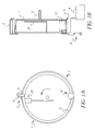
Figures 1A and 1B show a wave processor in which the method of the
invention may be performed.
The wave processor comprises a cylinder 1 having at least one open end.
The cylinder may be made of stainless steel, plastics or any other suitable
material. A transparent material, such as polycarbonate, may be used if it is
desired to scan the material while it is within the cylinder. The cylinder defines a
processing chamber. An arm 3 is provided on the outer side of the cylinder for
holding a film cassette 4. A slot 6 with a water tight cover (not shown) is
provided through the wall of the cylinder to allow the strip of film 5 from the film
cassette to enter the processing chamber. The watertight cover may be in the form
of a hinged door having a rubber wedge. However, any suitable means may be
used. A circular slot is defined around the inner circumference of the chamber for
holding the strip of film 5 by the edges.
A second arm 21 is located within the chamber. This arm 21 grabs the
tongue of the film and holds it against the inner circumference of the chamber.
A close fitting cover (not shown) may be provided around the inner
circumference of the chamber which sits above the film surface by at least 0.5mm.
This cover provides at least three functions to improve the performance of the
apparatus. Firstly it lowers water evaporation which can cause a temperature drop
and can concentrate the processing solution as processing is occurring. Secondly
it can itself provide agitation by maintaining a puddle of solution in the gap
between the cover and the film surface at the lowest point of the chamber. Thirdly
it provides a film retaining means making edge guides unnecessary, although edge
guides can be also be provided to prevent the film sticking to the cover. It allows
both 35mm film and APS film (24mm) to be loaded in the same apparatus and it
also allows any length of film to be loaded. The material of the cover can be
impervious to processing solution and as such is provided with a break or gap in
its circumference so that the two extreme ends of the cover do not meet and
through which processing solution is added to the film surface. The cover may be
fixed and rotate with the chamber as the chamber rotates. Alternatively the cover
may not be fixed and rests on rails on each side which allow the cover to slide and
remain stationary as the chamber rotates. In this case the cover is again provided
with a break or gap in its circumference so that processing solutions can be added
to the film surface. Alternatively the cover can be made of a material which is
porous to processing solution such as a mesh material or a material punctured with
holes. The cover can be made of plastic, metal, or any suitable material.
A drive shaft 2 is provided at the closed end of the cylinder for rotation
thereof. The open end of the cylinder 1 is provided with a flange 7. The flange
retains solution within the chamber. In the apparatus shown in figure 1B the
processing solutions are introduced into and removed from the chamber by means
of syringes 8. However any suitable means may be used, for example metering
pumps. The solutions may be introduced from a reservoir 9. Alternatively the
solutions may be held in a cartridge prior to use. The cartridge can consist of part
or all the processing solutions required to complete the process and is easily
placed or "plugged in" the processor without the need to open or pour solutions.
The cartridge can consist of an assembly of containers for each of the solutions
required for the process. The solutions may be removed by suction or any other
means. Residue of solutions therefore do not build up within the processing
chamber. This results in the processing chamber being essentially self cleaning.
The cross over times from one solution to another are very short.
A wave forming mechanism is provided within the processing chamber.
This wave forming mechanism sweeps the film surface and forms a wave of
solution, primarily at the lowest point in the chamber. In the apparatus shown in
Figure 1 the mechanism is a free standing roller 10. It is possible that this roller
may be held on a loose spindle, (not shown), which would allow the roller to be
steered and also to be raised and lowered into position. The position of the roller
can be changed with this mechanism so that it is to the left or right of bottom dead
centre which can be advantageous for the smooth running of the roller. It is also
desirable to raise or lower the roller which might facilitate film loading.
In operation a film cassette 4 is located in the arm 3 and held on the
outside of the cylinder 1. The end of the film 5 is withdrawn from the cassette and
entered into the processing chamber by means of the slot 6. The arm 21 holds the
film against the inner circumference of the cylinder and the cylinder 1 is rotated so
that the film 5 is unwound from the cassette and loaded into the processing
chamber. The film is held in a circular configuration within the processing
chamber. This loading is carried out while the processing chamber is dry although
it is also possible to load the film if the chamber is wet. The film is held with the
emulsion side facing inwards with respect to the chamber. It is also possible to
load the film with the emulsion side facing outwards provided a gap is present
between the film surface and the inner circumference of the chamber. Once
loaded, the film is held by the edges thereof within the circular slot around the
circumference of the chamber.
The processing chamber is heated. The chamber can be heated electrically
or by hot air. Alternatively the chamber may be heated by passing the lower end
thereof through a heated water bath. The chamber is then rotated. When the
desired temperature is reached a given volume of a first processing solution is
introduced into the chamber. The processing solution may be heated prior to
being introduced into the chamber. Alternatively the solution may be unheated or
cooled. As the chamber rotates the film is continuously re-wetted with the given
volume of solution.
Processing solution is added onto the roller 10 which is contacted across
the whole width thereof by a spreader. The spreader may be made of flexible soft
plastic, rigid plastic or any other suitable material. The roller 10 rotates in contact
with the spreader. Processing solution is delivered, via a supply pipe, down the
spreader to the region of contact between the roller and the spreader. This
delivery method forms a uniform bead of solution over the region of contact
between the roller and the spreader which extends across the width of the roller
10. This allows uniform spreading of the processing solution onto the film 5 as it
passes under the roller 10. It is also possible to add solutions very quickly by
"dumping" a given volume into the chamber while it is rotating so that it
immediately forms a "puddle" or wave in front of the roller. Yet another method
is to add the processing solutions when the chamber is stationary to a region
where there is no film or to a region where there is no image such as the fogged
end of the film. The rotation of the chamber is then started after the solution has
been added. The time interval between adding the solution and starting the
rotation can be from zero to any desired hold time.
The roller 10 acts as a wave forming mechanism. This wave forming
mechanism, in combination with the rotation of the chamber, provides very high
agitation which gives uniform processing even with very active processing
solutions. High agitation and mixing are required when only small volumes of
solution are being used, in the order of about 0.5 ml. If a large volume of solution
is added to the chamber in the absence of a wave forming mechanism a "puddle"
of solution is formed and spreading and agitation is achieved. However if a small
volume of solution is added to the chamber in the absence of a wave forming
mechanism then solution adheres to the film as the chamber rotates. There is no
"puddle" formed and there is consequently no agitation or mixing and processing
is slow and non-uniform. The agitation and mixing mechanism of the present
invention, i.e. the wave forming mechanism, is sufficient to minimise density
differences from the front to the back of the film.
Once the first stage of the processing is completed most of the processing
solution may be removed by suction. A given volume of the next processing
solution is then introduced into the chamber and then removed after the desired
time and so on. Finally, the wash solutions are added and removed. The normal
mode of operation is to perform the complete process cycle within the single
processing space of the rotating chamber. The process cycle may be develop,
stop, bleach, fix and wash. The processing solution for each stage is added to the
chamber and left for the required time. It is then removed and the next processing
solution is added and left for the required time, and so on until the process cycle is
complete. The film 5 may be dried in-situ with hot air. The whole process cycle
may thus be carried out within a single processing space.
All the solutions can be added at one delivery point and it is preferable to
add the solutions rapidly and to ensure that the volume added does not break-up
into separate droplets. The maintenance of a discrete volume can be facilitated by
"dumping" or "pouring" the solution through a wide tube which is situated close
to the inner circumference of the drum chamber so that the solution has only a
short distance to travel. In a processing stage which consists of two parts it is
necessary that the second part is added to the existing "puddle" or wave of the
first part. The method requires that at least the volume of the first part that is
added is more than that absorbed by the film so that the volume can be spread and
re-spread over the whole length of the film and so that a wave of solution can be
formed by means of the wave forming mechanism. The volume of the second part
can be more or can be less than that absorbed by the film since it is added on top
of the first part. The solutions can be added when the drum chamber is rotating or
when it is stationary. The drum chamber is essentially acting as a mixing chamber
for the first part and the second part. It is thus possible to arrange more complex
modes of addition where some fraction of the first part is added which is then
mixed with the second part and finally the rest of the volume of the first part is
added. Thus any fraction of the volume of the first part that is greater than the
volume absorbed by the film can be mixed with any fraction of the volume of the
second part and then the remaining volume of the first or second part can be added
subsequently. Thus it can be advantageous to add sufficient volume of the first
part to neutralise the acidity of the second part so that the solution within the drum
chamber is in the pH range 5 to 9. This is particularly advantageous if the
processing stage is the development stage since the majority of the components of
the developer solution can be spread on the film without development occurring.
The remainder of the first part or alkaline part is then added to start the
development. The method and apparatus of the invention easily allows very
complex sequences of solution addition similar to that described above which are
not possible with methods and apparatuses in the prior art.
It is possible to vary the timing of the addition of the first part and the
second part. Time t1 is defined as the time between the addition of the first part
and the addition of the second part and time t2 is defined as the time between the
addition of the second part and the addition of the solution for the next stage in the
process cycle. The total time for the stage is t1 + t2. The times t1 and t2 can be
varied to any desired amount. The times t1 and t2 can also include a solution
removal step or partial solution removal step which is started about five seconds
before the end of times t1 and t2. More complex timings can be made if a fraction
of the first part is used to neutralise the second part as described above.
It is also possible within the method of the invention to add the
components of a particular stage in the process, such as the development stage, the
bleach stage, the fix stage and the wash stage in more than two parts. The method
and apparatus of the invention is particularly suited to perform such complex
addition regimes because the solution addition station is in the same place for
different solutions and solutions can be added and removed merely by activating
delivery or removal pumps.
The method and apparatus of the invention allows all the advantages
described above while still using small volumes similar to those used to replenish
large standing tanks in conventional processing machines.
The method of the invention is described in more detail with reference to
the following examples.
Example 1
This is an example of the invention
In Table 1 two process cycles are compared in which the developer stage
in one case is a single solution and in the other case two solutions. The rest of the
process is identical in each case and is the standard C-41.
| Two stage and single stage development |
| | Process 1 | Process 2 |
| Stage | part 1 | part 2 | single part |
| Developer |
| | 5 sec | 25 sec | 30 sec |
| Stop | 30 sec | - | 30 sec |
| Bleach |
| | 3 min 30 sec | - | 3 min 30 sec |
| Fix |
| | 3 min 30 sec | - | 3 min 30 sec |
| Wash |
| | 2 minutes | - | 2 minutes |
Where Bleach is Kodak Flexicolor Bleach III NR and fix is Kodak Flexicolor
fixer and replenisher and the stop is 10% acetic acid. In Table 2 the composition
of the single developer solution is shown plus the composition of the two
concentrates. The two concentrates when mixed in the correct ratio combine to
form the same composition as the single developer solution.
| Single and two part developer composition |
| Developer | single part | two part (1) | two part (2) CD4 |
| Na2SO3(anhydrous) | 10.53 g/l | 10.81 g/l |
| HAS | 3 g/l | 3.36 g/l |
| DTPA | 2.6 g/l | 2.9 g/l |
| PVP(K15) | 3 g/l | 3.36 g/l |
| KI | 0.002 g/l | 0.0024 g/l |
| NaBr | 2.8 g/l | 3.14 g/l |
| K2CO3 | 40 g/l | 44.8 |
| Na2S2O5 | 0 | 0 | 7 g/l |
| CD4 | 15 g/l | 0 | 140 g/l |
| pH | 10.48 | 12.84 | - |
| Photoflo | 40 drops/l | 40 drops/l | 40 drops/l |
The last two columns show the composition of the two separate parts used for the
two stage development. These are added in the ratio 12.5/1.5 so that the
developer has the same composition as the single part developer shown in
column
2. In
process 2, 14 ml of the single part developer was added at a rate of 14 ml per
linear foot of 35 mm film. In fact the film was processed in the form of 1 foot
long 35 mm strips and 14 ml of the single part developer was added as the
processor was rotating. After 30 seconds, 4 ml of stop bath was then added to the
developer and after another 30 seconds the solution was removed and the bleach
solution was added. The bleach solution was removed after 3 minutes 30 seconds
and the fix solution was added. The fix was removed after 3 minutes 30 seconds
and the strip removed from the processor and washed for two minutes in a wash
tower with freely flowing water. Throughout this time the processor was rotating
and agitation was provided by means of a roller as described above with reference
to Figure 1. In process 1, 12.5 ml of part 1 of the developer was added as the
drum was rotating and 5 seconds afterwards 1.5 ml of part two of the developer
was added. After a total time of 30 seconds the stop bath was added and the
process was then the same as
process 2. The single development (process 2) and
the two stage development (process 1) were compared according to the process
cycles in Table 1 at 60° C. The results with an experimental 400 ISO colour
negative film are shown in Table 3 and Table 4.
| Single part development (process 2) |
| | R | G | B |
| Dmin | 0.147 | 0.643 | 0.96 |
| Dmax | 0.85 | 1.61 | 2.55 |
| Gamma | 0.34 | 0.44 | 0.61 |
| BFC | 0.29 | 0.4 | 0.6 |
| KitSpd | 342.38 | 337.06 | 340.45 |
| Spd0_2 | 281.94 | 307.41 | 316.27 |
| Inspd | 337.12 | 351.06 | 342.14 |
| Two part development (process 1) |
| | R | G | B |
| Dmin | 0.180 | 0.664 | 1.06 |
| Dmax | 1.09 | 2.06 | 2.7 |
| Gamma | 0.48 | 0.61 | 0.64 |
| BFC | 0.45 | 0.57 | 0.62 |
| KitSpd | 344.40 | 337.98 | 339.52 |
| Spd0_2 | 293.63 | 317.39 | 316.03 |
| Inspd | 325.09 | 343.72 | 337.44 |
It can be seen from Tables 3 and 4 that the photographic performance of the two
part development is superior to that of the one part development. The parameters
are as follows; Dmin = minimum density including masking dyes, Dmax is the
maximum density at the highest exposure given, Gamma is the point contrast,
BFC is the best fit contrast, KitSpd, Spd0_2 and Inspd are three different
photographic speed measures. For short development times such as 30 seconds it
is usually found for films designed for the standard C-41 development time of 3
minutes 15 seconds that the red and green contrasts are lower than the blue. This
can be seen for the single part development in Table 3, the Gamma and BFC
parameters are low for the red and green compared with the blue. In fact the red
contrast is about 50% of the blue and the green contrast is about 67% of the blue.
In Table 4 the two stage development has much higher red and green contrasts; in
this case the green is 90-95% of the blue and the red is 72-75% of the blue. Thus
the two stage development shows a significant improvement over the single part
development yet the total process time is the same and the total amount of
developer chemicals used is the same.
It was also observed that the uniformity of the two stage development was
excellent and so mixing of two component parts directly into the dry processing
tank onto dry film is a viable method.
The two component parts as used in the two stage development are stable
for long periods of at least 1 year. A pre-mixed developer as used in the single
part development(process 2) is stable only for a few weeks.
The developer component parts could be separated into more than two
partial stages. In this case the development stage could be more than two partial
stages. Two or more of the component parts could be mixed in the processing
tank or mixed before adding to the processing tank. The method of using more
than one partial stage for a given overall stage of a processing cycle can be
extended to other processing stages such as the bleach, fix, bleach-fix and
stabiliser or to any other stage of a process. The method can be used for colour
negative, colour reversal, black and white, film or paper processing. Although the
method has been described as used in an apparatus as shown in the drawings the
method is not limited to use in such a processor.
Example 2
This is an example of the invention.
The developer in Table 5 was made as a single part.
| Developer composition |
| Component | Concentration |
| Na3PO4.12H2O | 50g/l |
| DEHA | 5ml/l |
| KBr | 8g/l |
| Na2SO3 | 2g/l |
| CD4 | 10g/l |
| Tween 80 | 10drops/ |
| pH | 12.0 |
This developer was used at 14ml/linear foot of 35mm film in the process cycle
shown in Table 6.
| Process cycle |
| Develop | 30sec | 14ml/linear foot of 35mm |
| Stop | 20sec | 4ml/linear foot of 35mm |
| Bleach | 3min 30sec | large tank(2litres) |
| Fix | 3min 30sec | large tank(2litres) |
| wash | 2minutes |
where the stop was 10% acetic acid, the bleach was Kodak Flexicolor Bleach III
NR and fix was Kodak Flexicolor C-41b Fixer.
The same developer was also made from two parts as shown in Table 7.
| Two part developer(B) |
| Component | Part(1) | Part(2) |
| Na3PO4.12H2O | 53.8g/l | - |
| DEHA | 5.38ml/l | - |
| KBr | 8.6g/l | - |
| Na2SO3 | 2.15g/l | - |
| Na2S2O5 | - | 7g/l |
| CD4 | - | 140g/l |
| Tween 80 | 11 drops/l | 1drop/l |
| pH | 12.2 | - |
where; DEHA is diethylhydroxylamine, CD4 is 4-amino-3-methyl-N-ethyl-N-(β-hydroxyethyl)aniline
sulfate, Tween 80 is a commercially available polyoxy
ethylene surfactant.
These two parts are used with 13ml/linear foot of 35mm film of Part (1) and
1ml/linear foot of Part (2). Part (1) was added first and after 5 seconds (t1) part (2)
was added and the development was continued for a further 25 seconds (t2) to give
a total development time of 30 seconds.
A comparison between one part and two part development is shown in
Figure 2. Here it can be seen that the two stage development is an improvement
over the single stage development. Over-development in the blue layer is
prevented, the red layer is more active and the red and blue layers are more similar
in contrast compared to the single development case. Thus the invention has been
demonstrated.
The invention has been described in detail with reference to certain
preferred embodiments thereof. It will be understood by those skilled in the art
that variations and modifications can be effected within the scope of the invention.