EP1203765A2 - Process for the synthesis of urea - Google Patents
Process for the synthesis of urea Download PDFInfo
- Publication number
- EP1203765A2 EP1203765A2 EP01125270A EP01125270A EP1203765A2 EP 1203765 A2 EP1203765 A2 EP 1203765A2 EP 01125270 A EP01125270 A EP 01125270A EP 01125270 A EP01125270 A EP 01125270A EP 1203765 A2 EP1203765 A2 EP 1203765A2
- Authority
- EP
- European Patent Office
- Prior art keywords
- urea
- solution
- carbon dioxide
- gas mixture
- ammonia
- Prior art date
- Legal status (The legal status is an assumption and is not a legal conclusion. Google has not performed a legal analysis and makes no representation as to the accuracy of the status listed.)
- Granted
Links
Images


Classifications
-
- C—CHEMISTRY; METALLURGY
- C07—ORGANIC CHEMISTRY
- C07C—ACYCLIC OR CARBOCYCLIC COMPOUNDS
- C07C273/00—Preparation of urea or its derivatives, i.e. compounds containing any of the groups, the nitrogen atoms not being part of nitro or nitroso groups
- C07C273/02—Preparation of urea or its derivatives, i.e. compounds containing any of the groups, the nitrogen atoms not being part of nitro or nitroso groups of urea, its salts, complexes or addition compounds
- C07C273/04—Preparation of urea or its derivatives, i.e. compounds containing any of the groups, the nitrogen atoms not being part of nitro or nitroso groups of urea, its salts, complexes or addition compounds from carbon dioxide and ammonia
Definitions
- the present invention is directed to an improved, more efficient and economical process for the synthesis of urea from carbon dioxide and ammonia:
- This process involves reacting ammonia and carbon dioxide to form urea, followed by separation of unreacted ammonia and carbon dioxide by stripping with carbon dioxide at a pressure approximately equal to the urea synthesis pressure and by high and low pressure decomposition of residual ammonium carbamate.
- the process of the present invention efficiently uses off-gases from the high and low pressure decomposition and condensates of these gases and provides a more economical processes for synthesizing urea. For instance, improved conservation and recovery of heat provided by the present invention reduces process costs and improves the overall efficiency and economy of urea synthesis.
- Urea is synthesized by reacting carbon dioxide and ammonia at a high temperature and pressure. Conventionally, this reaction is performed inside of a urea synthesis zone or reactor at a suitable pressure and temperature for synthesis of urea and involves the formation and subsequent dehydration of ammonium carbamate to form urea: As shown above, the formation of ammonium carbamate and its subsequent dehydration into urea essentially occur simultaneously yielding urea. However, purity and yield of urea in the resulting reaction mixture (urea synthesis solution) can be improved by stripping using carbon dioxide and by high-pressure decomposition of ammonium carbonate.
- Urea may be synthesized by the following process steps:
- an uncondensed gas mixture containing inert gas, ammonia, carbon dioxide and water remains.
- This uncondensed gas mixture is washed in a scrubber using an absorption medium to absorb ammonia and carbon dioxide in the uncondensed gas mixture. After scrubbing substantially only the inert gas is discharged from the scrubber to the outside of the system.
- Japanese Patent Laid-Open No. 61-109760 discloses that such an inert gas may be introduced into the high pressure decomposition step of the unreacted ammonium carbamate remaining in the urea synthesis solution after carbon dioxide stripping.
- One object of the present invention is to provide a process with improved heat economy for synthesizing area that comprises stripping unreacted ammonium carbamate using carbon dioxide (e.g. raw material carbon dioxide) under a pressure equal to the urea synthesis pressure.
- carbon dioxide e.g. raw material carbon dioxide
- the phrases, "condense a gas mixture” or “condensing a gas mixture” may optionally encompass condensing and washing a gas mixture, condensing and absorbing a gas mixture, or both.
- the condensation of the high-pressure gas mixture or off-gases resulting from the high-pressure decomposition may be carried out by:
- gas from a high pressure decomposition column is condensed in at least two steps (or in three steps including the condensation occurring in the aqueous urea solution heating apparatus).
- gas from a scrubber may also be condensed together with the gas from the high-pressure decomposition.
- the present invention allows the use of condensates having a pressure equal to the pressure of the high pressure decomposition column as an absorption medium for gases from the high pressure decomposition column without requiring a further increase of pressure.
- the urea synthesis conditions are preferably as follows:
- the conditions for stripping the urea synthesis solution from the urea synthesis with raw material carbon dioxide are preferably as follows: the pressure is approximately equal to the urea synthesis pressure and the temperature ranges from about 160 to 200°C.
- the gas mixture of ammonia, carbon dioxide and water separated by stripping the urea synthesis solution is introduced into the bottom part of a condensation zone (condenser).
- the condensation conditions are preferably about 160 to 180°C for the temperature, about 3.0 to 4.5 for N/C and approximately 1 or lower for H/C.
- the gas mixture is condensed by contacting it with an aqueous ammonium carbamate solution residing in a condenser and at that time, whereby condensation heat is generated.
- the condensation heat is recovered by generation of low pressure steam.
- the gas mixture of an inert gas, ammonia, carbon dioxide and water which is not condensed in the condensation zone is introduced into a scrubber installed in the top part of the condensation zone and washed with the condensate of a gas mixture from high pressure decomposition, which will be described later.
- the resulting washing solution is introduced into the bottom of the condensation zone through a down pipe installed in the condensation zone.
- Most of ammonia and carbon dioxide in the above-described gas mixture are absorbed and together with remaining ammonia and carbon dioxide to discharge the inert gas from the scrubber.
- the discharged inert gas is utilized for stripping, as it will be described later, preferably in the high pressure decomposition.
- the condensate flows down through the down pipe laid in the condensation zone and having an opening in the upper part, enter an ejector derived by raw material ammonia having a pressure of about 15 to 30 MPa and a temperature of about 100 to 200°C, whereby the pressure of the condensate is increased by about 0.2 to 1 Mpa.
- the condensate is then introduced into the urea synthesis zone (e.g. element "A" in Figs. 1, 2 and 3).
- the pressure of the urea synthesis solution from the stripping step is reduced to about 1 to 4 MPaG, preferably 1.5 to 2.5 MPaG, and introduced into the high pressure decomposition step to decompose the unreacted ammonium carbamate remaining in the synthesis solution to a gas mixture of ammonia, carbon dioxide and water at the temperature of 120 to 170°C.
- the inert gas from the above-described scrubber may be introduced into the high pressure decomposition to be used as a stripping agent. In such a manner, the unreacted ammonium carbamate remaining in the aqueous urea solution can be decreased.
- the aqueous urea solution from the high pressure decomposition still contains a small amount of the unreacted ammonium carbamate.
- the aqueous urea solution is further decreased in pressure to about 0.1 to 0.5 MPaG and the unreacted ammonium carbamate is decomposed at about 100 to 130°C.
- some of raw material carbon dioxide may be used as a stripping agent. In such a manner, ammonia in the aqueous urea solution can be substantially removed.
- the aqueous urea solution containing substantially no ammonia from the low pressure decomposition (e.g. element "H" in Figs. 1, 2 and 3) is introduced into a concentration (evaporation) apparatus through a pipe side of an indirect heat exchanger.
- the gas mixture from the high pressure decomposition is introduced into the trunk part of the indirect heat exchanger to be heat-exchanged with the aqueous urea solution.
- the aqueous urea solution is heated by condensation heat generated at that time.
- the condensation heat of the high pressure gas mixture is utilized for concentrating the aqueous urea solution.
- the aqueous urea solution heated by the condensation heat may further be heated by low pressure steam.
- the concentration is preferably carried out at about 100 to 130°C.
- the condensation of the high pressure gas mixture is preferably carried out at about 100 to 120°C. The condensation may be carried out under a normal or reduced pressure.
- the condensate and the uncondensed gas mixture from the indirect heat exchanger are introduced into a first zone of high pressure condensation where the uncondensed gas mixture is partially condensed under cooling.
- the remaining uncondensed gas mixture is further introduced into a second zone of the high pressure condensation while the resulting condensate is fed to a scrubber to be used for absorbing the ammonia and carbon dioxide in the uncondensed gas mixture.
- the gas mixture is further condensed under cooling and the condensate is introduced into the trunk part of the indirect heat exchanger (e.g. element "K" in Figs. 1, 2 and 3) to be used for the condensation of the high pressure gas obtained from the high pressure decomposition step (e.g. element "G" in Figs. 1, 2 and 3).
- the uncondensed gas still remaining in the second step of the high pressure condensation mainly contains inert gas, but is further washed with an absorption medium in a washing column (e.g. element R in Figs. 1, 2 and 3) to remove residual ammonia and carbon dioxide from the inert gas.
- the remaining inert gas is discharged out of the top of the washing column.
- the washing solution from the bottom part of the washing column is fed to the second step of the high pressure condensation (e.g. element "Q" in Figs. 1, 2 and 3).
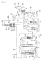
- the gas mixture containing the inert gas from the scrubber may be used as a stripping agent in the high pressure decomposition (see e.g. Fig. 1, element “G”); alternatively it may be mixed together with the gas mixture from the high pressure decomposition and introduced into the trunk part of the indirect heat exchanger for heating the aqueous urea solution (see e.g. Fig. 2, element “K”); alternatively, it may also be directly introduced to a first step of high pressure condensation of the gas mixture from the high pressure decomposition to be condensed (see e.g. Fig. 3, element "P").
- a part of liquid ammonia with the pressure of about 15 to 30 MPaG from the line 1 is preheated to about 100 to 200°C with high or low pressure steam in a preheater D and then fed to the driving side of an ejector E to increase the pressure of a condensate aspirated through a down pipe 3 of a condenser C by 0.2 to 1 Mpa.
- the ammonia from the ejector E is introduced into the bottom part of a urea synthesis column A together with carbon dioxide containing about 0.2 to 5% by volume of air as oxygen.
- the urea synthesis column A is operated at a pressure ranging from about 13 to 25 MPaG, a temperature ranging from about 180 to 200°C, an N/C ratio of about 3.5 to 5.0, and an H/C ratio of about 1.0 or less.
- the introduced ammonia, carbon dioxide, and the condensate are converted to urea while rising in the synthesis column and the produced urea synthesis solution is introduced into the top part of a stripper B at a pressure substantially equal to the urea synthesis pressure through the line 4.
- the urea synthesis solution While flowing down in the stripper B, the urea synthesis solution is brought into contact with carbon dioxide fed in counter flow through a line 2B at 160 to 200°C to separate the unreacted ammonium carbamate contained in the urea synthesis solution as a gas mixture of ammonia, carbon dioxide, an inert gas and water.
- the separated gas mixture is introduced into the bottom part of the condenser C through the line 5.
- the gas mixture is brought into contact with a washing liquid flowing down from a scrubber F installed in the top part through a washing liquid receiver 7 and a down pipe 8 to the bottom part of the condenser to be condensed at 170 to 190°C.
- the condensation heat generated at that time is eliminated by generating steam from water introduced from a line 9 and discharged through a line 10.
- the resulting condensate flows down in the down pipe 3 having the opening in the upper part of the condenser and is introduced, as described above, into the synthesis column A through the ejector E.
- the remaining of the liquid ammonia from the line 1 is supplied to the condenser C through a line 1A to maintain the N/C ratio at 3.0 to 4.5 and the H/C ratio at 1 or less in the condensate in the condenser C.
- a high pressure absorption solution which will be described later, is introduced into the scrubber F to wash the uncondensed gas mixture of the inert gas, ammonia, and carbon dioxide, thereby absorbing a part of ammonia and carbon dioxide in the gas mixture.
- a gas mixture of mainly an inert gas is discharged from the top part of the scrubber.
- the pressure of the urea synthesis solution from which the major part of the unreacted ammonium carbamate is separated in the stripper B is reduced to a preferable pressure of from 1.2 to 2.5 MPaG and the solution is then introduced through a line 12 into a high pressure decomposition column G and heated to 120 to 160°C to decompose most of the unreacted ammonium carbamate.
- the inert gas from the line 11 is introduced into the bottom part of the high pressure decomposition column G as a stripping agent to make separation of the unreacted ammonium carbamate easy.
- a gas mixture of ammonia, carbon dioxide, the inert gas and water is discharged through a line 20 from the top of the column.
- the resulting urea synthesis solution from which most of the unreacted ammonium carbamate is separated in the high pressure decomposition column G flows through the line 13 and after the pressure of the solution is reduced to 0.1 to 0.5 MPaG, the solution is introduced into the top of a low pressure decomposition tower H and heated to 110 to 140°C to separate the substantially all of the remaining unreacted ammonium carbamate as a gas mixture of ammonia, carbon dioxide and water.
- any of the raw material carbon dioxide may be introduced as a stripping agent from a line 2C into the bottom part of the low pressure decomposition column.
- the separated gas mixture is discharged through a line 26.
- An aqueous urea solution discharged from the bottom part of the low pressure decomposition column H through a line 14 is introduced through the line 15 into a gas-liquid separator I after the pressure is decreased to a normal pressure, and the gas mixture of ammonia, carbon dioxide and water in a slight amount is separated and discharged through a line 17.
- the resulting aqueous urea solution is introduced into an aqueous urea solution storage tank J through a line 16.
- the aqueous urea solution from the aqueous urea solution storage tank J flows through a line 19 and is fed to a condensing part K and then a heating part L of an aqueous urea solution heating apparatus by means of a pump 18 to be heated.
- the urea solution is then introduced into a concentration apparatus M through a line 23 to be concentrated, and the concentrated urea solution is taken out through a line 24.
- the evaporated steam accompanied with slight amounts of ammonia and carbon dioxide is discharged through a line 25.
- the gas mixture from the line 20 and a condensate from a line 21, which will be described later, are introduced into the trunk side of the condensing part K of the aqueous urea solution heating apparatus to be condensed by indirect heat exchange with the aqueous urea solution flowing in the pipe side.
- the aqueous urea solution is heated with the condensation heat of the gas mixture generated at that time.
- the temperature of the trunk part of the condensing part K is kept at 100 to 120°C.
- Steam is introduced into the trunk part of the heating part L of the aqueous urea solution heating apparatus to heat the aqueous urea solution flowing in the pipe side to about 110 to 138°C.
- the condensed liquid and the uncondensed gas mixture obtained in the condensation part of the aqueous urea solution heating apparatus are introduced into the trunk part of a first condenser P through a line 22 and are cooled by water flowing in the pipe side to be condensed.
- the temperature of the trunk side of the first condenser P is kept at about 90 to 120°C.
- the produced condensate is sent to the scrubber F through a line 6.
- the uncondensed gas mixture is introduced into the trunk part of a second condenser Q through a line 29 and condensed under cooling by being brought into contact with a high pressure washing solution, which will be described later, introduced through the line 31.
- the obtained condensate is sent to the condensing part K of the aqueous urea solution heating apparatus as described above through the line 21.
- the temperature of the trunk side of the second condenser Q is kept at about 40 to 70°C.
- the gas mixture which is not condensed in the trunk side of the second condenser Q is introduced through a line 30 into a washing column and brought into contact with the low pressure condensate introduced from the top part through a line 28 and pressurized at a pressure of about 1.2 to 2.5 MPaG to absorb substantially all of the remaining ammonia and carbon dioxide.
- the inert gas that is not absorbed is discharged out through the line 32.
- the gas mixture separated in a lower pressure decomposition column H is sent to a low pressure condenser N, and brought into contact under cooling with an aqueous diluted ammonium carbonate solution (which may contain a slight amount of urea) introduced through the line 27, which solution has absorbed slight amounts of ammonia and carbon dioxide from lines 17, 25 (and a gas mixture separated in a condenser if there is the condenser after the low pressure decomposition column H) to be condensed to be a low pressure condensate which is then introduced from the line 28 into the washing column R after the pressure is increased.
- aqueous diluted ammonium carbonate solution which may contain a slight amount of urea
- the process shown in Figure 1 was carried out as follows.
- the urea synthesis reaction was conducted at the temperature of 182°C and the pressure of 15.2 MPaG in an urea synthesis column by introducing 39,588.75 kg/hr of liquid ammonia heated to 140°C by a preheater D through line 1, 7,140.00 kg/hr of raw material carbon dioxide through line 2A which was supplied in 52,639.17 kg/hr together with 1,205 kg/hr of air and an inert gas through line 2, and a condensate containing 50,604.46 kg/hr of urea, 57,049.10 kg/hr of ammonia, 45,132.18 kg/hr of carbon dioxide, 36,655.50 kg/hr of water, and 154.59 kg/hr of biuret through down pipe 3.
- the separated gas mixture was introduced into the bottom part of condenser C and while rising through condenser C, was brought into contact with a high pressure condensate containing:
- the gas mixture obtained from low pressure decomposition column H was introduced into a low pressure condenser N through line 26 and brought into contact under cooling with an aqueous diluted ammonium carbonate solution containing a slight amount of urea (from line 27) and was condensed.
- This condensate of gases from the low pressure decomposition contained:
- the condensate was introduced into the trunk side of th.e condensing part K of the aqueous urea solution heating apparatus through line 21 and condensed at a temperature of 110°C together with the gas mixture from the high pressure decomposition column G introduced through line 20 while being indirectly heat-exchanged with the aqueous urea solution sent through line 19 from the aqueous urea solution storage tank J.
- Line 22 exits the indirect heat-exchanger and contained an uncondensed gas mixture of:
- aqueous urea solution stored in tank J as described above was introduced into condensing part K of the aqueous urea solution heating apparatus, then into heating part L of the aqueous urea solution heating apparatus and then further heated by steam and introduced into a concentration apparatus M through a line 23 to obtain urea solution containing approximately 95 % urea by weight.
- gas composition in line 20 ammonia 8,623.33 kg/hr carbon dioxide 13,611.25 kg/hr water 3,510.00 kg/hr urea synthesis solution composition in line 13: urea 72,747.30 kg/hr ammonia 8,746.37 kg/hr carbon dioxide 4,373.49 kg/hr water 33,418.89 kg/hr biuret 358.95 kg/hr
- liquid composition in the line 28 urea 249.17 kg/hr ammonia 9,400.41 kg/hr carbon dioxide 7,335,84 kg/hr water 11,021.25 kg/hr liquid composition in line 31: urea 249.17 kg/hr ammonia 9,788.32 kg/hr carbon dioxide 7,339.59 kg/hr water 11,035.41 kg/hr gas composition in line 30: ammonia 394.58 kg/hr carbon dioxide 10.42 kg/hr water 35.83 kg/hr the inert gas 1,205.00 kg/hr gas composition in line 32: ammonia 6.67 kg/hr carbon dioxide 6.67 kg/hr water 21.67 kg/hr the inert gas 1,205.00 kg/hr
- liquid composition in line 22 urea 249.17 kg/hr ammonia 14,955.31 kg/hr carbon dioxide 16,761.24 kg/hr water 14,092.94 kg/hr gas composition in line 22: ammonia 8,631.85 kg/hr carbon dioxide 5,987.92 kg/hr water 1,541.19 kg/hr
- liquid composition in line 6 urea 249.17 kg/hr ammonia 19,154.99 kg/hr carbon dioxide 22,909.59 kg/hr water 14,665.00 kg/hr gas composition in line 11: ammonia 1,137.92 kg/hr carbon dioxide 1,969.17 kg/hr water 155.42 kg/hr
- the inert gas 1,205.00 kg/hr gas composition in line 29 ammonia 5,570.09 kg/hr carbon dioxide 1,808.74 kg/hr water 1,124.55 kg/hr the inert gas 1,205.00 kg/hr
- aqueous urea solution in line 19 urea 72,230.09 kg/hr ammonia 467.34 kg/hr carbon dioxide 342.72 kg/hr water 27,111.52 kg/hr biuret 367.52 kg/hr
- aqueous urea solution in line 24 urea 71,922.45 kg/hr ammonia 0 kg/hr carbon dioxide 0 kg/hr water 3810.89 kg/hr biuret 484.48 kg/hr
Landscapes
- Chemical & Material Sciences (AREA)
- Organic Chemistry (AREA)
- Organic Low-Molecular-Weight Compounds And Preparation Thereof (AREA)
Abstract
Description


- 66,607.50 kg/hr of ammonia,
- 61,227.50 kg/hr of carbon dioxide, and
- 6,442.92 kg/hr of water.
- 10,497.36 kg/hr of ammonia,
- 16,841.16 kg/hr of carbon dioxide,
- 1,205.00 kg/hr of an inert gas, and
- 3,516.68 kg/hr of water through
line 20.
- 72,747.30 kg/hr of urea,
- 8,010.27 kg/hr of ammonia,
- 3,112.75 kg/hr of carbon dioxide,
- 33,567.62 kg/hr of water, and
- 358.95 kg/hr of biuret
- 249.17 kg/hr of urea,
- 9,052.21 kg/hr of ammonia,
- 6,078.85 kg/hr of carbon dioxide, and
- 11,184.15 kg/hr of water.
- 5,990.82 kg/hr of ammonia,
- 1,684.14 kg/hr of carbon dioxide,
- 1,023.48 kg/hr of water, and
- 1,205.00 of an inert gas
- 249.17 kg/hr of urea,
- 14,648.45 kg/hr of ammonia,
- 7,752.55 kg/hr of carbon dioxide, and
- 12,171.80 kg/hr of water.
- 249.17 kg/hr of urea,
- 14,638.08 kg/hr of ammonia,
- 17,184.87 kg/hr of carbon dioxide, and
- 14,144.35 kg/hr of water
- 249.17 kg/hr of urea,
- 19,154.99 kg/hr of ammonia,
- 22,909.59 kg/hr of carbon dioxide, and
- 14,665.00 kg/hr of water.
| gas composition in line 20: | |
| ammonia | 8,623.33 kg/hr |
| carbon dioxide | 13,611.25 kg/hr |
| water | 3,510.00 kg/hr |
| urea synthesis solution composition in line 13: | |
| urea | 72,747.30 kg/hr |
| ammonia | 8,746.37 kg/hr |
| carbon dioxide | 4,373,49 kg/hr |
| water | 33,418.89 kg/hr |
| biuret | 358.95 kg/hr |
| gas composition in line 26: | |
| ammonia | 8,380.43 kg/hr |
| carbon dioxide | 6,409.63 kg/hr |
| water | 3,049.56 kg/hr |
| aqueous urea solution in line 14: | |
| urea | 72,230.09 kg/hr |
| ammonia | 655.14 kg/hr |
| carbon dioxide | 492.02 kg/hr |
| water | 30,217.13 kg/hr |
| biuret | 367.25 kg/hr |
| liquid composition in line 28: | |
| urea | 249.17 kg/hr |
| ammonia | 9,400.41 kg/hr |
| carbon dioxide | 7,335.84 kg/hr |
| water | 11,021.25 kg/hr |
| liquid composition in line 31: | |
| urea | 249.17 kg/hr |
| ammonia | 9,788.32 kg/hr |
| carbon dioxide | 7,339.59 kg/hr |
| water | 11,035.41 kg/hr |
| gas composition in line 30: | |
| ammonia | 394.58 kg/hr |
| carbon dioxide | 10.42 kg/hr |
| water | 35.83 kg/hr |
| the inert gas | 1,205.00 kg/hr |
| gas composition in line 32: | |
| ammonia | 6.67 kg/hr |
| carbon dioxide | 6.67 kg/hr |
| water | 21.67 kg/hr |
| inert gas | 1,205.00 kg/hr |
| liquid composition in line 21: | |
| urea | 249.17 kg/hr |
| ammonia | 14,964.47 kg/hr |
| carbon dioxide | 8,887.21 kg/hr |
| water | 12,066.34 kg/hr |
| gas composition in the line 11: | |
| ammonia | 1,137.92 kg/hr |
| carbon dioxide | 1,969.17 kg/hr |
| water | 155.42 kg/hr |
| the inert gas | 1,205.00 kg/hr |
| liquid composition in line 22: | |
| urea | 249.17 kg/hr |
| ammonia | 14,954.82 kg/hr |
| carbon dioxide | 17,613.42 kg/hr |
| water | 14,122.33 kg/hr |
| gas composition in line 22: | |
| ammonia | 9,770.89 kg/hr |
| carbon dioxide | 6,854.21 kg/hr |
| water | 1,609.43 kg/hr |
| the inert gas | 1,205.00 kg/hr |
| liquid composition in line 6: | |
| urea | 249.17 kg/hr |
| ammonia | 19,154.99 kg/hr |
| carbon dioxide | 22,909.59 kg/hr |
| water | 14,665.00 kg/hr |
| gas composition in line 29: | |
| ammonia | 5,570.73 kg/hr |
| carbon dioxide | 1,558.04 kg/hr |
| water | 1,066.76 kg/hr |
| the inert gas | 1,205.00 kg/hr |
| aqueous urea solution in line 19: | |
| urea | 72,230.09 kg/hr |
| ammonia | 467.34 kg/hr |
| carbon dioxide | 342.72 kg/hr |
| water | 27,111.52 kg/hr |
| biuret | 367.52 kg/hr |
| aqueous urea solution in line 24: | |
| urea | 71,922.45 kg/hr |
| ammonia | 0 kg/hr |
| carbon dioxide | 0 kg/hr |
| water | 3810.89 kg/hr |
| biuret | 484.48 kg/hr |
| gas composition in line 20: | |
| ammonia | 8,623.33 kg/hr |
| carbon dioxide | 13,611.25 kg/hr |
| water | 3,510.00 kg/hr |
| urea synthesis solution composition in line 13: | |
| urea | 72,747.30 kg/hr |
| ammonia | 8,746.37 kg/hr |
| carbon dioxide | 4,373.49 kg/hr |
| water | 33,418.89 kg/hr |
| biuret | 358.95 kg/hr |
| gas composition in line 26: | |
| ammonia | 8,380.43 kg/hr |
| carbon dioxide | 6,409.63 kg/hr |
| water | 3,049.56 kg/hr |
| aqueous urea solution in line 14: | |
| urea | 72,230.09 kg/hr |
| ammonia | 655.14 kg/hr |
| carbon dioxide | 492.02 kg/hr |
| water | 30,217.13 kg/hr |
| biuret | 367.25 kg/hr |
| liquid composition in the line 28: | |
| urea | 249.17 kg/hr |
| ammonia | 9,400.41 kg/hr |
| carbon dioxide | 7,335,84 kg/hr |
| water | 11,021.25 kg/hr |
| liquid composition in line 31: | |
| urea | 249.17 kg/hr |
| ammonia | 9,788.32 kg/hr |
| carbon dioxide | 7,339.59 kg/hr |
| water | 11,035.41 kg/hr |
| gas composition in line 30: | |
| ammonia | 394.58 kg/hr |
| carbon dioxide | 10.42 kg/hr |
| water | 35.83 kg/hr |
| the inert gas | 1,205.00 kg/hr |
| gas composition in line 32: | |
| ammonia | 6.67 kg/hr |
| carbon dioxide | 6.67 kg/hr |
| water | 21.67 kg/hr |
| the inert gas | 1,205.00 kg/hr |
| In line 21: | |
| urea | 249.17 kg/hr |
| ammonia | 14,963.83 kg/hr |
| carbon dioxide | 9,137.91 kg/hr |
| water | 12,124.13 kg/hr |
| liquid composition in line 22: | |
| urea | 249.17 kg/hr |
| ammonia | 14,955.31 kg/hr |
| carbon dioxide | 16,761.24 kg/hr |
| water | 14,092.94 kg/hr |
| gas composition in line 22: | |
| ammonia | 8,631.85 kg/hr |
| carbon dioxide | 5,987.92 kg/hr |
| water | 1,541.19 kg/hr |
| liquid composition in line 6: | |
| urea | 249.17 kg/hr |
| ammonia | 19,154.99 kg/hr |
| carbon dioxide | 22,909.59 kg/hr |
| water | 14,665.00 kg/hr |
| gas composition in line 11: | |
| ammonia | 1,137.92 kg/hr |
| carbon dioxide | 1,969.17 kg/hr |
| water | 155.42 kg/hr |
| the inert gas | 1,205.00 kg/hr |
| gas composition in line 29: | |
| ammonia | 5,570.09 kg/hr |
| carbon dioxide | 1,808.74 kg/hr |
| water | 1,124.55 kg/hr |
| the inert gas | 1,205.00 kg/hr |
| aqueous urea solution in line 19: | |
| urea | 72,230.09 kg/hr |
| ammonia | 467.34 kg/hr |
| carbon dioxide | 342.72 kg/hr |
| water | 27,111.52 kg/hr |
| biuret | 367.52 kg/hr |
| aqueous urea solution in line 24: | |
| urea | 71,922.45 kg/hr |
| ammonia | 0 kg/hr |
| carbon dioxide | 0 kg/hr |
| water | 3810.89 kg/hr |
| biuret | 484.48 kg/hr |
| Ex. 1 | Ex. 2 | Ex.3 | |
| Column G-high pressure decomposition | |||
| line 20 (gas) | |||
| ammonia | 10,497.36 | 8,623.33 | 8,623.33 |
| carbon dioxide | 16,841.16 | 13,611.25 | 13,611.25 |
| water | 3,516.68 | 3,510.00 | 3,510.00 |
| inert gas | 1,205.00 | 0 | 0 |
| line 13 (urea synthesis solution) | |||
| urea | 72,747.30 | 72,747.30 | 72,747.30 |
| ammonia | 8,010.27 | 8,746.37 | 8,746.37 |
| carbon dioxide | 3,112.75 | 4,373.49 | 4,373.49 |
| water | 33,567.62 | 33,418.89 | 33,418.89 |
| biuret | 358.95 | 358.95 | 358.95 |
| line 11 (gas) | |||
| ammonia | 1,137.92 | N/A | N/A |
| carbon dioxide | 1,969.17 | N/A | N/A |
| water | 155.42 | N/A | N/A |
| inert gas | 1,205.00 | N/A | N/A |
| Column H-low pressure decomposition | |||
| line 26 (gas) | |||
| ammonia | 7,644.32 | 8,380.43 | 8,380.43 |
| carbon dioxide | 5,148.89 | 6,409.63 | 6,409.63 |
| water | 3,198.30 | 3,049.56 | 3,049.56 |
| line 14 (aqueous solution) | |||
| urea | 72,230.09 | 72,230.09 | 72,230.09 |
| ammonia | 663.15 | 655.14 | 655.14 |
| carbon dioxide | 492.02 | 492.02 | 492.02 |
| water | 30,217.42 | 30,217.13 | 30,217.13 |
| biuret | 367.25 | 367.25 | 367.25 |
| Column R-washing | |||
| line 28 (liquid) | |||
| urea | 249.17 | 249.17 | 249.17 |
| ammonia | 8,664.30 | 9,400.41 | 9,400.41 |
| carbon dioxide | 6,075.10 | 7,335.84 | 7,335.84 |
| water | 11,169.99 | 11,021.25 | 11,021.25 |
| line 31 (liquid) | |||
| urea | 249.17 | 249.17 | 249.17 |
| ammonia | 9,052.21 | 9,788.32 | 9,788.32 |
| carbon dioxide | 6,078.85 | 7,339.59 | 7,339.59 |
| water | 11,184.15 | 11,035.41 | 11,035.41 |
| line 30 (gas) | |||
| ammonia | 394.58 | 394.58 | 394.58 |
| carbon dioxide | 10.42 | 10.42 | 10.42 |
| water | 35.83 | 35.83 | 35.83 |
| inert gas | 1,205.00 | 1,205.00 | 1,205.00 |
| line 32 (gas) | |||
| ammonia | 6.67 | 6.67 | 6.67 |
| carbon dioxide | 6.67 | 6.67 | 6.67 |
| water | 21.57 | 21.67 | 21.67 |
| inert gas | 1,205.00 | 1,205.00 | 1,205.00 |
| Condenser Q (second condenser) | |||
| line 21 (liquid) | |||
| urea | 249.17 | 249.17 | 249.17 |
| ammonia | 14,648.45 | 14,964.47 | 14963.83 |
| carbon dioxide | 7,752.55 | 8,887.21 | 9137.91 |
| water | 12,171.80 | 12,066.34 | 12124.13 |
| Condensation part K | |||
| line 11 (gas) | |||
| ammonia | N/A | 1,137.92 | N/A |
| carbon dioxide | N/A | 1,969.17 | N/A |
| water | N/A | 155.42 | N/A |
| inert gas | N/A | 1,025.00 | N/A |
| line 22 (liquid) | |||
| urea | 249.17 | 249.17 | 249.17 |
| ammonia | 14,638.08 | 14,954.82 | 14,955.31 |
| carbon dioxide | 17,184.87 | 17,613.42 | 16,761.24 |
| water | 14,144.35 | 14,122.33 | 14,092.94 |
| line 22 (gas) | |||
| ammonia | 10,507.73 | 9,770.89 | 8,631.85 |
| carbon dioxide | 7,408.84 | 6,854.21 | 5,987.92 |
| water | 1,544.14 | 1,609.43 | 1,541.19 |
| inert gas | 1,205.00 | 1,205.00 | 0 |
| Condenser P (first condenser) | |||
| line 6 (liquid) | |||
| urea | 249.17 | 249.17 | 249.17 |
| ammonia | 19,154.99 | 19,154.99 | 19,154.99 |
| carbon dixoide | 22,909.59 | 22,909.59 | 22,909.59 |
| water | 14,665.00 | 14,665.00 | 14,665.00 |
| line 11 (gas) | |||
| ammonia | N/A | N/A | 1,137.92 |
| carbon dioxide | N/A | N/A | 1,969.17 |
| water | N/A | N/A | 155.42 |
| inert gas | N/A | N/A | 1,205.00 |
| line 29 (gas) | |||
| ammonia | 5,990.82 | 5,570.73 | 5,570.09 |
| carbon dioxide | 1,684.14 | 1,558.04 | 1,808.74 |
| water | 1,023.48 | 1,066.76 | 1,124.55 |
| inert gas | 1,205.00 | 1,205.00 | 1,205.00 |
| Concentration Apparatus M | |||
| line 19-aqueous urea solution | |||
| urea | 72,230.09 | 72,230.09 | 72,230.09 |
| ammonia | 467.34 | 467.34 | 467.34 |
| carbon dioxide | 342.72 | 342.72 | 342.72 |
| water | 27,111.52 | 27,111.52 | 27,111.52 |
| biuret | 367.52 | 367.52 | 367.52 |
| line 24-aqueous solution | |||
| urea | 71,922.45 | 71,922.45 | 71,922.45 |
| ammonia | - | - | - |
| carbon dioxide | - | - | - |
| water | 3,810.89 | 3,810.89 | 3,810.89 |
| biuret | 484.48 | 484.48 | 484.48 |
Claims (11)
- A process for synthesizing urea comprising:(a) reacting carbon dioxide with ammonia at temperature and pressure suitable for synthesis of urea in a urea synthesis zone to form a urea synthesis solution;(b) stripping said urea synthesis solution with carbon dioxide at a pressure substantially equal to the urea synthesis pressure to decompose unreacted ammonium carbamate contained in the urea synthesis solution as a gas mixture of ammonia, carbon dioxide and water;(c) condensing the gas mixture obtained from (b) and recycling the condensate into the urea synthesis zone;(d) decomposing at high pressure the unreacted ammonium carbamate in the urea synthesis solution obtained from stripping the urea synthesis solution, thereby decomposing unreacted ammonium carbamate remaining in the stripped urea synthesis solution into a gas mixture of ammonia, carbon dioxide and water;(e) decomposing at low pressure unreacted ammonium carbamate in the urea synthesis solution obtained from the high pressure decomposition, thereby obtaining a low pressure gas mixture of ammonia, carbon dioxide and water, and obtaining an aqueous urea solution substantially free of unreacted ammonium carbamate;(f) condensing the low pressure gas mixture obtained from the low pressure decomposition to obtain a condensate of the low pressure gas mixture;(g) condensing the high pressure gas mixture obtained from the high pressure decomposition of the urea synthesis solution by:(i) contacting it with a condensate of gases obtained from the high and low pressure decomposition of the urea synthesis solution,(ii) indirectly contacting the mixture of (i) with aqueous urea solution under conditions suitable for indirect heat exchange, thus heating the aqueous urea solution and obtaining a partially condensed mixture of gases,(iii) introducing the partially condensed mixture of gases (ii) into a first cooling and condensation zone under conditions suitable for further condensation of said mixture of gases, and recycling the resulting condensate to (c) to facilitate cooling and condensation of the gases obtained from (b),(iv) introducing the remaining uncondensed mixture of gases (iii) into a second cooling and condensation zone under conditions suitable for further condensation of said mixture of gases, and mixing the resulting condensate with the off-gases from high-pressure decomposition (d),(v) washing the remaining uncondensed gases from (iv) with a washing solution comprising the pressurized condensate of gases from low pressure decomposition (f), introducing said washing solution to the second cooling zone (iv), and optionally discharging inert gas.
- The process of Claim 1, wherein the carbon dioxide contains a slight amount of oxygen for corrosion protection.
- The process of Claim 1 or 2, wherein the high pressure decomposition is performed at a pressure ranging from 1 to 4 Mpa.
- The process of Claim 1, 2 or 3, wherein the low pressure decomposition is performed at a pressure ranging from 01. to 0.5 Mpa.
- The process of Claim 1, wherein the aqueous urea solution in (g) is further heated by steam.
- The process of any of preceding claims, wherein the uncondensed gas mixture obtained from condensing the gases obtained by stripping (b) the urea synthesis solution is introduced into the high pressure decomposition (d) of ammonium carbamate.
- The process of any of preceding claims, wherein the uncondensed gas mixture obtained from condensing the gases obtained by stripping (b) the urea synthesis solution is mixed with the gas mixture from the high-pressure decomposition (d) and the mixture is used to indirectly heat the aqueous urea solution.
- The process of any of preceding claims, wherein the uncondensed gas mixture obtained from condensing the gases obtained by stripping (b) the urea synthesis solution is introduced into a condenser for condensing uncondensed gases obtained from the high-pressure decomposition after the gas mixture from the high-pressure decomposition is partially condensed by indirect heat exchange with the aqueous urea solution.
- A process for synthesizing urea substantially as shown in Fig. 1.
- A process for synthesizing urea substantially as shown in Fig. 2.
- A process for synthesizing urea substantially as shown in Fig. 3.
Applications Claiming Priority (2)
| Application Number | Priority Date | Filing Date | Title |
|---|---|---|---|
| JP2000334395 | 2000-11-01 | ||
| JP2000334395A JP4358428B2 (en) | 2000-11-01 | 2000-11-01 | Urea production method |
Publications (3)
| Publication Number | Publication Date |
|---|---|
| EP1203765A2 true EP1203765A2 (en) | 2002-05-08 |
| EP1203765A3 EP1203765A3 (en) | 2003-10-08 |
| EP1203765B1 EP1203765B1 (en) | 2008-04-02 |
Family
ID=18810318
Family Applications (1)
| Application Number | Title | Priority Date | Filing Date |
|---|---|---|---|
| EP01125270A Expired - Lifetime EP1203765B1 (en) | 2000-11-01 | 2001-10-24 | Process for the synthesis of urea |
Country Status (5)
| Country | Link |
|---|---|
| US (1) | US6426434B1 (en) |
| EP (1) | EP1203765B1 (en) |
| JP (1) | JP4358428B2 (en) |
| BR (1) | BR0104896B1 (en) |
| DE (1) | DE60133445T2 (en) |
Cited By (6)
| Publication number | Priority date | Publication date | Assignee | Title |
|---|---|---|---|---|
| EP1918273A1 (en) * | 2006-11-04 | 2008-05-07 | Urea Casale S.A. | Process for urea production and related plant |
| CN101397144B (en) * | 2007-10-22 | 2010-05-26 | 贵州赤天化股份有限公司 | Method for absorbing ammonia by cooling down of high pressure shift temperature water from stripping urea plant |
| CN102786442A (en) * | 2012-08-16 | 2012-11-21 | 沧州大化股份有限公司 | Method of reducing energy consumption of synthetic feeding system of urea device |
| CN102816091A (en) * | 2011-06-10 | 2012-12-12 | 安徽省科捷再生能源利用有限公司 | Aqueous solution full-cycle urea energy-saving production process |
| CN103408466A (en) * | 2013-07-09 | 2013-11-27 | 内蒙古鄂尔多斯联合化工有限公司 | Equipment corrosion control method in producing urea by using CO2 stripping method |
| US9346016B2 (en) | 2005-03-09 | 2016-05-24 | Stamicarbon B.V. | Process for the preparation of a urea-comprising aqueous stream |
Families Citing this family (22)
| Publication number | Priority date | Publication date | Assignee | Title |
|---|---|---|---|---|
| US8853376B2 (en) | 2002-11-21 | 2014-10-07 | Archemix Llc | Stabilized aptamers to platelet derived growth factor and their use as oncology therapeutics |
| US20050124565A1 (en) * | 2002-11-21 | 2005-06-09 | Diener John L. | Stabilized aptamers to platelet derived growth factor and their use as oncology therapeutics |
| US10100316B2 (en) * | 2002-11-21 | 2018-10-16 | Archemix Llc | Aptamers comprising CPG motifs |
| US8039443B2 (en) * | 2002-11-21 | 2011-10-18 | Archemix Corporation | Stabilized aptamers to platelet derived growth factor and their use as oncology therapeutics |
| CA2523260A1 (en) | 2003-04-21 | 2004-11-04 | Archemix Corporation | Stabilized aptamers to platelet derived growth factor and their use as oncology therapeutics |
| JP2007527246A (en) * | 2004-03-05 | 2007-09-27 | アーケミックス コーポレイション | Aptamers against the human IL-12 cytokine family and their use as therapeutics for autoimmune diseases |
| US20060193821A1 (en) * | 2004-03-05 | 2006-08-31 | Diener John L | Aptamers to the human IL-12 cytokine family and their use as autoimmune disease therapeutics |
| US7579450B2 (en) * | 2004-04-26 | 2009-08-25 | Archemix Corp. | Nucleic acid ligands specific to immunoglobulin E and their use as atopic disease therapeutics |
| EP1807107B1 (en) | 2004-11-02 | 2011-09-07 | Archemix Corp. | Stabilized aptamers to platelet derived growth factor and their use as oncology therapeutics |
| CN101166714B (en) | 2005-04-27 | 2011-11-30 | 东洋工程株式会社 | Urea synthesis unit |
| CH698707B1 (en) | 2005-04-27 | 2009-10-15 | Toyo Engineering Corp | A device for the synthesis of urea and kit for retrofitting an existing such apparatus. |
| CA2613442C (en) | 2005-06-30 | 2016-08-23 | Archemix Corp. | Materials and methods for the generation of fully 2'-modified nucleic acid transcripts |
| US8101385B2 (en) | 2005-06-30 | 2012-01-24 | Archemix Corp. | Materials and methods for the generation of transcripts comprising modified nucleotides |
| ITMI20071029A1 (en) * | 2007-05-22 | 2008-11-23 | Snam Progetti | IMPROVED PROCEDURE FOR THE SYNTHESIS OF UREA |
| US7687041B2 (en) * | 2008-02-27 | 2010-03-30 | Kellogg Brown & Root Llc | Apparatus and methods for urea production |
| EP2437054B1 (en) * | 2009-05-28 | 2015-12-02 | Toyo Engineering Corporation | Method for analyzing aqueous ammonium carbamate solution and process for producing urea |
| EP2505581A1 (en) * | 2011-03-31 | 2012-10-03 | Stamicarbon B.V. | Zero emission urea process and plant |
| US10501407B2 (en) | 2015-09-08 | 2019-12-10 | Toyo Engineering Corporation | Urea manufacturing method and urea manufacturing apparatus |
| WO2017192032A1 (en) * | 2016-05-03 | 2017-11-09 | Stamicarbon B.V. | Urea production with controlled biuret |
| IT201700121364A1 (en) * | 2017-10-25 | 2019-04-25 | Saipem Spa | APPARATUS AND METHOD FOR PROCESSING PROCESSED VAPORS FROM A VACUUM CONCENTRATION SECTION OF A UREA PLANT |
| CN109879342B (en) * | 2019-04-23 | 2024-04-26 | 宁波马克斯迈环保科技有限公司 | Sour water stripper distillate heat utilization device and method |
| JP2023108791A (en) * | 2022-01-26 | 2023-08-07 | 東洋エンジニアリング株式会社 | Urea synthesis method |
Family Cites Families (9)
| Publication number | Priority date | Publication date | Assignee | Title |
|---|---|---|---|---|
| JPS5750954A (en) * | 1980-09-12 | 1982-03-25 | Mitsui Toatsu Chem Inc | Synthesis of urea |
| NL8303888A (en) * | 1983-11-13 | 1985-06-03 | Unie Van Kunstmestfab Bv | METHOD FOR THE PREPARATION OF UREA. |
| JPS6215070A (en) | 1985-07-12 | 1987-01-23 | Honda Motor Co Ltd | Phase indexing device in crankpin grinding machine |
| NL8502227A (en) | 1985-08-12 | 1987-03-02 | Unie Van Kunstmestfab Bv | METHOD FOR THE PREPARATION OF UREA. |
| NL8502228A (en) | 1985-08-12 | 1987-03-02 | Unie Van Kunstmestfab Bv | METHOD FOR THE PREPARATION OF UREA. |
| JPS63112552A (en) | 1986-10-30 | 1988-05-17 | Toyo Eng Corp | Separation method for unconverted substance |
| NL8602770A (en) | 1986-11-03 | 1988-06-01 | Stamicarbon | METHOD FOR THE PREPARATION OF UREA. |
| NL8800259A (en) | 1988-02-04 | 1989-09-01 | Stamicarbon | METHOD FOR CONCENTRATING A UREA SOLUTION |
| JP3987607B2 (en) | 1996-10-07 | 2007-10-10 | 東洋エンジニアリング株式会社 | Improved urea synthesis method and apparatus |
-
2000
- 2000-11-01 JP JP2000334395A patent/JP4358428B2/en not_active Expired - Lifetime
-
2001
- 2001-10-24 EP EP01125270A patent/EP1203765B1/en not_active Expired - Lifetime
- 2001-10-24 DE DE60133445T patent/DE60133445T2/en not_active Expired - Lifetime
- 2001-10-30 US US09/984,486 patent/US6426434B1/en not_active Expired - Lifetime
- 2001-10-31 BR BRPI0104896-1A patent/BR0104896B1/en not_active IP Right Cessation
Cited By (9)
| Publication number | Priority date | Publication date | Assignee | Title |
|---|---|---|---|---|
| US9346016B2 (en) | 2005-03-09 | 2016-05-24 | Stamicarbon B.V. | Process for the preparation of a urea-comprising aqueous stream |
| EP1918273A1 (en) * | 2006-11-04 | 2008-05-07 | Urea Casale S.A. | Process for urea production and related plant |
| WO2008052639A1 (en) * | 2006-11-04 | 2008-05-08 | Urea Casale S.A. | Process for urea production and related plant |
| RU2446152C2 (en) * | 2006-11-04 | 2012-03-27 | Уреа Касале С.А. | Method of producing urea and apparatus for realising said method |
| CN101558037B (en) * | 2006-11-04 | 2013-08-07 | 卡萨尔尿素公司 | Process for urea production and related plant |
| CN101397144B (en) * | 2007-10-22 | 2010-05-26 | 贵州赤天化股份有限公司 | Method for absorbing ammonia by cooling down of high pressure shift temperature water from stripping urea plant |
| CN102816091A (en) * | 2011-06-10 | 2012-12-12 | 安徽省科捷再生能源利用有限公司 | Aqueous solution full-cycle urea energy-saving production process |
| CN102786442A (en) * | 2012-08-16 | 2012-11-21 | 沧州大化股份有限公司 | Method of reducing energy consumption of synthetic feeding system of urea device |
| CN103408466A (en) * | 2013-07-09 | 2013-11-27 | 内蒙古鄂尔多斯联合化工有限公司 | Equipment corrosion control method in producing urea by using CO2 stripping method |
Also Published As
| Publication number | Publication date |
|---|---|
| JP4358428B2 (en) | 2009-11-04 |
| DE60133445T2 (en) | 2008-07-03 |
| BR0104896B1 (en) | 2011-12-13 |
| DE60133445D1 (en) | 2008-05-15 |
| US20020082451A1 (en) | 2002-06-27 |
| EP1203765A3 (en) | 2003-10-08 |
| US6426434B1 (en) | 2002-07-30 |
| BR0104896A (en) | 2003-04-08 |
| JP2002145850A (en) | 2002-05-22 |
| EP1203765B1 (en) | 2008-04-02 |
Similar Documents
| Publication | Publication Date | Title |
|---|---|---|
| US6426434B1 (en) | Process for the synthesis of urea | |
| US4314077A (en) | Method for the production of urea and purification of water | |
| US6585807B2 (en) | Recovery method of ammonia from gaseous mixture | |
| EP0093466B1 (en) | Process for the preparation of urea | |
| EP0752416B1 (en) | Method and apparatus for recovering condensables in vapor from a urea vacuum evaporator | |
| US4053507A (en) | Method of recovering unreacted materials and heat in urea synthesis | |
| JPH093032A (en) | Integrating method for ammonia/urea | |
| EP0019326A1 (en) | Process for purifying urea-containing waste water and process for preparing melamine | |
| RU2043336C1 (en) | Method of synthesis of urea from ammonia and carbon dioxide | |
| US6586629B1 (en) | Method of introducing melamine off-gases into a urea plant | |
| EP2521710B1 (en) | A urea stripping process for the production of urea | |
| EP0086805B1 (en) | Process for the preparation of urea | |
| EP0145054B1 (en) | Process for preparing urea | |
| RU2050351C1 (en) | Method of carbamide synthesis | |
| SU1153825A3 (en) | Method of obtaining urea | |
| RU2854494C2 (en) | Method and plant for synthesis of urea and melamine | |
| AU2023384852B2 (en) | Coupled urea melamine production with hp co2 stripping | |
| RU2069657C1 (en) | Method of producing urea | |
| EP0136764A2 (en) | Process for the preparation of urea | |
| WO2025053758A1 (en) | Ammonium nitrate production with multiple condensers | |
| EP0086804A1 (en) | Process for the preparation of urea | |
| AU2023384849A1 (en) | Coupled urea melamine plant | |
| EP0136765A2 (en) | Process for the preparation of urea | |
| EA052793B1 (en) | UREA AND MELAMINE CO-PRODUCTION WITH HIGH-PRESSURE CO2 BLASTING | |
| RU2172732C2 (en) | Method for synthesis of urea from ammonia and carbon dioxide (options) |
Legal Events
| Date | Code | Title | Description |
|---|---|---|---|
| PUAI | Public reference made under article 153(3) epc to a published international application that has entered the european phase |
Free format text: ORIGINAL CODE: 0009012 |
|
| AK | Designated contracting states |
Kind code of ref document: A2 Designated state(s): AT BE CH CY DE DK ES FI FR GB GR IE IT LI LU MC NL PT SE TR |
|
| AX | Request for extension of the european patent |
Free format text: AL;LT;LV;MK;RO;SI |
|
| PUAL | Search report despatched |
Free format text: ORIGINAL CODE: 0009013 |
|
| AK | Designated contracting states |
Kind code of ref document: A3 Designated state(s): AT BE CH CY DE DK ES FI FR GB GR IE IT LI LU MC NL PT SE TR |
|
| AX | Request for extension of the european patent |
Extension state: AL LT LV MK RO SI |
|
| 17P | Request for examination filed |
Effective date: 20040205 |
|
| AKX | Designation fees paid |
Designated state(s): CH DE IT LI NL |
|
| 17Q | First examination report despatched |
Effective date: 20050504 |
|
| GRAP | Despatch of communication of intention to grant a patent |
Free format text: ORIGINAL CODE: EPIDOSNIGR1 |
|
| GRAS | Grant fee paid |
Free format text: ORIGINAL CODE: EPIDOSNIGR3 |
|
| GRAA | (expected) grant |
Free format text: ORIGINAL CODE: 0009210 |
|
| AK | Designated contracting states |
Kind code of ref document: B1 Designated state(s): CH DE IT LI NL |
|
| REG | Reference to a national code |
Ref country code: CH Ref legal event code: EP |
|
| REF | Corresponds to: |
Ref document number: 60133445 Country of ref document: DE Date of ref document: 20080515 Kind code of ref document: P |
|
| REG | Reference to a national code |
Ref country code: CH Ref legal event code: NV Representative=s name: R. A. EGLI & CO. PATENTANWAELTE |
|
| PLBE | No opposition filed within time limit |
Free format text: ORIGINAL CODE: 0009261 |
|
| STAA | Information on the status of an ep patent application or granted ep patent |
Free format text: STATUS: NO OPPOSITION FILED WITHIN TIME LIMIT |
|
| 26N | No opposition filed |
Effective date: 20090106 |
|
| PGFP | Annual fee paid to national office [announced via postgrant information from national office to epo] |
Ref country code: DE Payment date: 20171024 Year of fee payment: 17 |
|
| REG | Reference to a national code |
Ref country code: DE Ref legal event code: R119 Ref document number: 60133445 Country of ref document: DE |
|
| PG25 | Lapsed in a contracting state [announced via postgrant information from national office to epo] |
Ref country code: DE Free format text: LAPSE BECAUSE OF NON-PAYMENT OF DUE FEES Effective date: 20190501 |
|
| PGFP | Annual fee paid to national office [announced via postgrant information from national office to epo] |
Ref country code: NL Payment date: 20201006 Year of fee payment: 20 |
|
| PGFP | Annual fee paid to national office [announced via postgrant information from national office to epo] |
Ref country code: IT Payment date: 20201006 Year of fee payment: 20 Ref country code: CH Payment date: 20201021 Year of fee payment: 20 |
|
| REG | Reference to a national code |
Ref country code: NL Ref legal event code: MK Effective date: 20211023 |
|
| REG | Reference to a national code |
Ref country code: CH Ref legal event code: PL |