EP1203739A2 - Low friction envelope feeder - Google Patents
Low friction envelope feeder Download PDFInfo
- Publication number
- EP1203739A2 EP1203739A2 EP01125457A EP01125457A EP1203739A2 EP 1203739 A2 EP1203739 A2 EP 1203739A2 EP 01125457 A EP01125457 A EP 01125457A EP 01125457 A EP01125457 A EP 01125457A EP 1203739 A2 EP1203739 A2 EP 1203739A2
- Authority
- EP
- European Patent Office
- Prior art keywords
- rod
- stack
- envelopes
- rotation axis
- supporting surface
- Prior art date
- Legal status (The legal status is an assumption and is not a legal conclusion. Google has not performed a legal analysis and makes no representation as to the accuracy of the status listed.)
- Withdrawn
Links
Images



Classifications
-
- B—PERFORMING OPERATIONS; TRANSPORTING
- B65—CONVEYING; PACKING; STORING; HANDLING THIN OR FILAMENTARY MATERIAL
- B65H—HANDLING THIN OR FILAMENTARY MATERIAL, e.g. SHEETS, WEBS, CABLES
- B65H1/00—Supports or magazines for piles from which articles are to be separated
- B65H1/02—Supports or magazines for piles from which articles are to be separated adapted to support articles on edge
- B65H1/025—Supports or magazines for piles from which articles are to be separated adapted to support articles on edge with controlled positively-acting mechanical devices for advancing the pile to present the articles to the separating device
-
- B—PERFORMING OPERATIONS; TRANSPORTING
- B65—CONVEYING; PACKING; STORING; HANDLING THIN OR FILAMENTARY MATERIAL
- B65H—HANDLING THIN OR FILAMENTARY MATERIAL, e.g. SHEETS, WEBS, CABLES
- B65H2701/00—Handled material; Storage means
- B65H2701/10—Handled articles or webs
- B65H2701/19—Specific article or web
- B65H2701/1916—Envelopes and articles of mail
Definitions
- the present invention relates generally to an envelope feeder and, more specifically, to an envelope feeder in an envelope insertion machine.
- a gathering section where the enclosure material is gathered before it is inserted into an envelope.
- This gathering section includes a gathering transport with pusher fingers rigidly attached to a conveying means and a plurality of enclosure feeders mounted above the transport. If the enclosure material contains many documents, these documents are separately fed by different enclosure feeders. After all the released documents are gathered, they are put into a stack to be inserted into an envelope in an inserting station. At the same time, envelopes are sequentially fed to the inserting station, and each envelope is placed on a platform with its flap flipped back all the way, so that a plurality of mechanical fingers or a vacuum suction device can keep the envelope on the platform while the throat of the envelope is pulled away to open the envelope.
- envelopes Before envelopes are fed to the insertion station, they are usually supplied in a stack in a supply tray or envelope hopper. Envelopes are then separated by an envelope feeder so that only one envelope is fed to the insertion station at a time. For that reason, an envelope feeder is also referred to as an envelope singulator. In a high-speed insertion machine, the feeder should be able to feed single envelopes at a rate of approximately 18,000 No.10 envelopes per hour. At this feeding rate, it is critical that only a single envelope at a time is picked up and delivered to the insertion station.
- the first aspect of the present invention is an envelope hopper having an upstream end and a downstream end for providing a stack of envelopes to an envelope feeder located near the downstream end.
- the envelope hopper comprises:
- the second bottom rod also rotates in order to reduce the friction between the stack of envelopes and the supporting surface.
- the envelope hopper also has a side rod parallel to the rotation axis and is located above the supporting surface for registering the stack of envelopes, and the side rod is adapted to rotate in order to reduce the friction between the stack of envelopes and the side rod.
- the supporting surface is titled from the horizontal surface, urging the envelopes to move toward the side rod in order to register against the side rod.
- the pivot is located above the supporting surface and on the opposite side of the side rod.
- the second aspect of the present invention is a method for moving a stack of envelopes on an envelope hopper, wherein the stack of envelopes is supported by a supporting surface and urged to move from an upstream end towards a downstream end in a moving direction.
- the method comprises the steps of:
- the second bottom rod also rotates in order to reduce the friction between the stack of envelopes and the supporting surface.
- Figure 1 is an isometric representation illustrating the envelope hopper of the present invention.
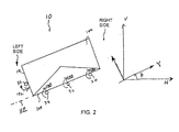
- Figure 2 is a diagrammatic representation illustrating the tilting of the supporting surface from a horizontal surface.
- Figure 3 is a diagrammatic representation illustrating the rotation axis of the scrub wheel in relation to the rotation axis of the bottom rods.
- Figure 4 is a vector diagram showing the relation between the velocity vector of the wheel and the velocity vector the bottom rod.
- Figure 5 is a vector diagram showing the relation between the total normal force between the wheel and the bottom rod and the force in the paddle advance direction.
- Figure 6 is a diagrammatic representation showing moments about the pivot of the paddle arising from various forces.
- FIG 1 illustrates the envelope hopper 10 of the present invention.
- the envelope hopper 10 includes a plurality of polished, bottom rods 30-34 for supporting a stack of envelopes 100 and providing the envelopes 100 to an envelope feeder 20 at the downstream end of the envelope hopper 10.
- the orientation of the envelope hopper 10 can be described in reference to a set of mutually orthogonal axes X, Y and Z.
- the rods 30-34 form a supporting surface 112 (see Figure 2), which is parallel to the XY plane.
- the bottom rods 30-34 are substantially parallel to the X axis.
- the envelope hopper 10 is tilted to the left such that the XY plane is rotated by angle ⁇ from a horizontal surface defined by the horizontal axis H.
- a polished, side rod 36 which is also substantially parallel to X axis, is provided above the supporting surface 112 on the left-side of the envelope hopper 10 to register the left edge 102 of the envelopes 100, while the envelopes 100 are moved towards the envelope feeder 20 from upstream to downstream by an envelope pusher assembly 40.
- the envelope pusher assembly 40 includes a stack advance paddle 42 pivotally mounted at pivot 46.
- the envelope pusher assembly 40 also has a rotatable scrub wheel 44 mounted on the stack advance paddle 42 at a fixed location.
- the scrub wheel 44 is positioned at an angle ⁇ with respect to the stack advance paddle 42 and rests on top of the rod 30 (see Figure 3).
- the rods 30-34 are driven by a motor 50 via a belt 52 and a plurality of rollers 54, 56 to rotate along a rotating direction 130 along rotation axes 240-244, respectively.
- the rim 48 of the scrub wheel 44 has a frictional surface so that when the bottom rod 30 rotates along the rotation direction 130, it exerts a steering force on the stack advance paddle 42 towards the downstream direction through the scrub wheel 44.
- the envelope pusher assembly 40 is slidably mounted on a track 38, which is also parallel to the X axis, so that it can be urged by the scrub wheel 44 to move from upstream towards downstream.
- the side rod 36 is also driven by the motor 50 to rotate along a direction 132 opposite to the rotation direction 130 in order to aid the envelopes 100 to register against the side rod 36 and to reduce the friction between the envelopes 100 and the rod 36.
- the top edge 104 of the envelope 100 can be support by two of the bottom rods 30-32.
- the left edge 102 of the envelope 100 has a tendency to move toward and rest on the side rod 36.
- the scrub wheel 44 is caused to rotate along a rotation direction 134, along a rotation axis 246, when the bottom rod 30 rotates along the rotation direction 130.
- a stack 110 of envelopes 100 being pushed in the X direction towards the downstream end.
- the arrangement of the scrub wheel 44 and the stack advance paddle 42 in relation to the rotation axis of the bottom rod 30 provides a rapid advance motion in the X direction for the stack advance paddle 42, when there is little or no force acting on the stack advance paddle 42 by the envelopes 100.
- the rapid advance motion only occurs when the hopper is refilled with envelopes and a gap (not shown) is produced between the envelope stack 110 and the stack advance paddle 42.
- the paddle 42 encounters resistant forces in the stack 110.
- the paddle velocity decreases.
- V x is the maximum velocity of the paddle 42 during a no-load condition, when the paddle 42 does not encounter the envelope stack 110.
- V X V R sin ⁇ cos ⁇ Wherein V R is the velocity of the bottom rod 30.
- V W is the velocity of the scrub wheel 44.
- the optimal velocity depends on the surface of the bottom rod 30, the surface of the scrub wheel 44 and the friction between the scrub wheel 44 and the axis 45 on which it is mounted.
- the above equations will usually give only a rough estimate of the required rod velocity V R .
- the optimal velocity of the bottom rods is preferably fifteen (15) inches per second, creating a near frictionless surface.
- the bottom rods have a corresponding angle ⁇ of preferably 10° to 20°, and the titling angle ⁇ of the hopper relative to a horizontal surface has been found to be advantageous at 30°.
- the given values for the aforesaid angles ⁇ and ⁇ are only given as preferred angles and may be varied to suit any given application of use.
- the rotation of the bottom rods 32, 34 will also reduce the friction between the envelope stack 110 and the rods 32, 34, or the friction between the envelope stack 110 and the support surface 112. It is possible to have one or more other scrub wheels, responsive to the rotation of the bottom rods 32 and 34, to provide additional force for pushing the stack advance paddle 42 towards the downstream end of the envelope hopper 10. However, this variation does not depart from the principle of using a rotating rod and a scrub wheel to provide a pushing force to the envelope stack, according to the present invention.
Landscapes
- Engineering & Computer Science (AREA)
- Mechanical Engineering (AREA)
- Sheets, Magazines, And Separation Thereof (AREA)
Abstract
Description
Claims (15)
- An envelope hopper having an upstream end and a downstream end for providing a stack of envelopes to an envelope feeder located near the downstream end, said envelope hopper comprising:a rod, having a first rotation axis substantially parallel to a moving direction, running from the upstream end to the downstream end;supporting means, which is co-located on a plane with the rod in order to form a supporting surface to support the stack of envelopes;a pushing device, located behind the stack of envelopes and pivotally mounted at a pivot positioned above the supporting surface, for urging the stack of envelopes to move along the moving direction towards the envelope feeder; androtation means, having a second rotation axis, rotatably mounted on the pushing device and positioned to make contact with the rod, with the second rotation axis oriented at an angle relative to the first rotation axis, wherein the rod is adapted to rotate along the first rotation axis, causing the rotation means to rotate along the second rotation axis in response to the rotation of the rod, thereby producing an urging force on the pushing device towards the downstream end.
- The envelope hopper of claim 1, wherein the support means comprises at least one further rod having a third rotation axis substantially parallel to the first axis.
- The envelope hopper of claim 2, wherein said at least one further rod is adapted to rotate along the third rotation axis in order to reduce friction between the further rod and the stack of envelopes.
- The envelope hopper in any one of the preceding claims, wherein the rotation means comprises a wheel having a perimeter surface in order to produce a friction force between the wheel and the rod.
- The envelope hopper of any one of the preceding claims, further comprising means, mounted above the support surface, for registering the stack of envelopes.
- The envelope hopper of claim 5, wherein the registering means comprises a further rod.
- The envelope hopper of claim 6, wherein the further rod is adapted to rotate in order to reduce friction between the further rod and the stack of envelopes.
- The envelope hopper of claim 7, wherein the rod rotates along a first rotation direction and the further rod rotates along a second rotation direction, which is opposite to the first rotation direction.
- The envelope hopper of claim 8, wherein the supporting surface has a first side and an opposing second side separated by a distance along a further direction, which is substantially perpendicular to the first rotation axis, and wherein the supporting surface is tilted to the first side relative to a horizontal plane, and the registering means is located on the first side of the supporting surface.
- The envelope hopper of claim 9, wherein the pivot is located on the second side of the support surface.
- A method for moving a stack of envelopes on an envelope hopper, wherein the stack of envelopes is supported by a supporting surface and urged to move from an upstream end towards a downstream end in a moving direction, said method comprising the steps of:providing a rod having a first rotation axis located on the supporting surface and oriented substantially parallel to the moving direction, wherein the rod is adapted to rotate; providing a pushing means located behind the stack of envelopes; andproviding a rotation means rotatably mounted on a second rotation axis on the supporting surface, wherein the second rotation axis is oriented at an angle relative to the first rotation axis, and wherein the rotation means has a frictional surface being in contact with the rod, causing the rotation means to rotate in response to the rotation of the rod, thereby producing an urging force on the pushing means to push the stack of envelopes towards the downstream end.
- The method of claim 11, further comprising the step of providing at least one further rod located on the supporting surface and being substantially parallel with the first rotation axis, wherein said at least one further rod is adapted to rotate in order to reduce friction between the stack of envelopes and the supporting surface.
- The method of claim 11, wherein the supporting surface has a first side and an opposing second side, separated by a distance along a direction substantially perpendicular to the moving direction, and wherein the supporting surface is tilted to the first side from a horizontal surface, said method further comprising the step of providing a registering means located above the supporting surface and on the first side of the supporting surface in order to register the stack of envelopes.
- The method of claim 13, wherein the registering means comprises a further rod having a third rotation axis substantially parallel to the first rotation axis, and wherein the further rod is adapted to rotate in order to reduce friction between the registering means and the stack of envelopes.
- The method of claim 13, wherein the pushing means is pivotally mounted above the supporting surface and on the second side thereof.
Applications Claiming Priority (2)
| Application Number | Priority Date | Filing Date | Title |
|---|---|---|---|
| US705268 | 1985-02-25 | ||
| US09/705,268 US6425579B1 (en) | 2000-11-03 | 2000-11-03 | Low friction envelope feeder |
Publications (2)
| Publication Number | Publication Date |
|---|---|
| EP1203739A2 true EP1203739A2 (en) | 2002-05-08 |
| EP1203739A3 EP1203739A3 (en) | 2003-10-08 |
Family
ID=24832727
Family Applications (1)
| Application Number | Title | Priority Date | Filing Date |
|---|---|---|---|
| EP01125457A Withdrawn EP1203739A3 (en) | 2000-11-03 | 2001-11-05 | Low friction envelope feeder |
Country Status (3)
| Country | Link |
|---|---|
| US (1) | US6425579B1 (en) |
| EP (1) | EP1203739A3 (en) |
| CA (1) | CA2361018A1 (en) |
Families Citing this family (6)
| Publication number | Priority date | Publication date | Assignee | Title |
|---|---|---|---|---|
| SE517069C2 (en) * | 2000-10-04 | 2002-04-09 | Tetra Laval Holdings & Finance | An apparatus and method for feeding packaging materials |
| US7025347B2 (en) * | 2002-09-17 | 2006-04-11 | Canon Denshi Kabushiki Kaisha | Sheet aligning apparatus |
| US7249762B1 (en) * | 2004-05-27 | 2007-07-31 | Unisys Corporation | System for feeding and transporting documents |
| US9334129B2 (en) * | 2012-06-05 | 2016-05-10 | Pitney Bowes Inc. | Method and apparatus for automated filling of a mail tray from a vertical stacker |
| US10087024B2 (en) | 2015-02-20 | 2018-10-02 | DMT Solutions Global Corp. | Envelope feeder with selective suction cup assist |
| IT201900003287A1 (en) * | 2019-03-07 | 2019-06-07 | Sandenvendo Europe S P A | Product conveyor device for vending machines |
Family Cites Families (10)
| Publication number | Priority date | Publication date | Assignee | Title |
|---|---|---|---|---|
| US3118393A (en) * | 1960-12-27 | 1964-01-21 | Xhiving means in a track system | |
| US3130967A (en) * | 1961-12-21 | 1964-04-28 | Alton Box Board Co | Hopper feed for carton blanks |
| GB1196909A (en) * | 1966-08-12 | 1970-07-01 | Post Office | Improvements in or relating to Drive Mechanisms |
| US4603720A (en) * | 1981-06-29 | 1986-08-05 | Si Handling Systems Inc. | Drive wheel for driverless vehicle |
| US4620280A (en) * | 1983-07-29 | 1986-10-28 | Si Handling Systems, Inc. | Intelligent driverless vehicle |
| US4884795A (en) * | 1988-05-26 | 1989-12-05 | Bell & Howell Company | Document feeder apparatus |
| US5092575A (en) * | 1990-09-05 | 1992-03-03 | Pitney Bowes Inc. | Portable apparatus for supporting sheets |
| US5993132A (en) * | 1996-03-29 | 1999-11-30 | Siemens Electrocom L.P. | Transferring a stack from a cartridge |
| US6250625B1 (en) * | 1999-12-16 | 2001-06-26 | Pitney Bowes Inc. | Method for supplying envelopes to an inserter system by way of multiple supply paths |
| US6270070B1 (en) * | 1999-12-21 | 2001-08-07 | Pitney Bowes Inc. | Apparatus and method for detecting and correcting high stack forces |
-
2000
- 2000-11-03 US US09/705,268 patent/US6425579B1/en not_active Expired - Lifetime
-
2001
- 2001-11-02 CA CA002361018A patent/CA2361018A1/en not_active Abandoned
- 2001-11-05 EP EP01125457A patent/EP1203739A3/en not_active Withdrawn
Also Published As
| Publication number | Publication date |
|---|---|
| CA2361018A1 (en) | 2002-05-03 |
| EP1203739A3 (en) | 2003-10-08 |
| US6425579B1 (en) | 2002-07-30 |
Similar Documents
| Publication | Publication Date | Title |
|---|---|---|
| US4509739A (en) | Apparatus for stacking letter mail | |
| JP2690376B2 (en) | Feeder front end feeder | |
| US4775142A (en) | Roller apparatus for side registration of documents | |
| EP1316521A1 (en) | Magazine apparatus and method for loading documents | |
| US5033729A (en) | Mechanism for the handling and singulating of flat materials | |
| WO1997030917A1 (en) | Magazine apparatus and method for loading documents | |
| WO1991015416A1 (en) | Flats mail singulation apparatus | |
| EP0038901A2 (en) | Document feed apparatus | |
| US20060087068A1 (en) | Anti-toppling device for mail and/or the like | |
| JPH04505908A (en) | Machine for automatic sorting of goods | |
| US6425579B1 (en) | Low friction envelope feeder | |
| CA2131554C (en) | Apparatus for stacking sheet-like articles | |
| JP2009524533A (en) | Device for collating flat objects and for further conveying collated objects | |
| FR2961417A1 (en) | DEVICE FOR STACKING FLAT OBJECTS ON THE EDGE, ITS STEERING METHOD, AND POSTAL SORTING MACHINE EQUIPPED WITH AT LEAST ONE SUCH DEVICE | |
| JPH0313135B2 (en) | ||
| EP0493108B1 (en) | Adjustable, high capacity sheet feeder | |
| US6585249B1 (en) | Low friction article feeding system | |
| US4723773A (en) | Sheet feeding methods and apparatus | |
| EP1620270B1 (en) | Decurler and stabilizer for light-weight papers | |
| US20080174066A1 (en) | Thick product feeder | |
| US20060000752A1 (en) | Stack correction system and method | |
| JP3159523B2 (en) | Paper sheet folding device | |
| US6463255B1 (en) | Sheet feeder, imaging system and method | |
| WO2001070606A1 (en) | Mail piece feeder for vertically orientated mail pieces and having reversible retard rollers | |
| JP2003137469A (en) | Paper stamping device |
Legal Events
| Date | Code | Title | Description |
|---|---|---|---|
| PUAI | Public reference made under article 153(3) epc to a published international application that has entered the european phase |
Free format text: ORIGINAL CODE: 0009012 |
|
| AK | Designated contracting states |
Kind code of ref document: A2 Designated state(s): AT BE CH CY DE DK ES FI FR GB GR IE IT LI LU MC NL PT SE TR |
|
| AX | Request for extension of the european patent |
Free format text: AL;LT;LV;MK;RO;SI |
|
| PUAL | Search report despatched |
Free format text: ORIGINAL CODE: 0009013 |
|
| AK | Designated contracting states |
Kind code of ref document: A3 Designated state(s): AT BE CH CY DE DK ES FI FR GB GR IE IT LI LU MC NL PT SE TR |
|
| AX | Request for extension of the european patent |
Extension state: AL LT LV MK RO SI |
|
| STAA | Information on the status of an ep patent application or granted ep patent |
Free format text: STATUS: THE APPLICATION HAS BEEN WITHDRAWN |
|
| 18W | Application withdrawn |
Effective date: 20040405 |