EP1203682A1 - Device for a work element having two degrees of mobility - Google Patents
Device for a work element having two degrees of mobility Download PDFInfo
- Publication number
- EP1203682A1 EP1203682A1 EP00985275A EP00985275A EP1203682A1 EP 1203682 A1 EP1203682 A1 EP 1203682A1 EP 00985275 A EP00985275 A EP 00985275A EP 00985275 A EP00985275 A EP 00985275A EP 1203682 A1 EP1203682 A1 EP 1203682A1
- Authority
- EP
- European Patent Office
- Prior art keywords
- working element
- mobility
- movable
- degrees
- base
- Prior art date
- Legal status (The legal status is an assumption and is not a legal conclusion. Google has not performed a legal analysis and makes no representation as to the accuracy of the status listed.)
- Withdrawn
Links
Images


Classifications
-
- B—PERFORMING OPERATIONS; TRANSPORTING
- B25—HAND TOOLS; PORTABLE POWER-DRIVEN TOOLS; MANIPULATORS
- B25J—MANIPULATORS; CHAMBERS PROVIDED WITH MANIPULATION DEVICES
- B25J9/00—Program-controlled manipulators
- B25J9/10—Program-controlled manipulators characterised by positioning means for manipulator elements
- B25J9/106—Program-controlled manipulators characterised by positioning means for manipulator elements with articulated links
-
- B—PERFORMING OPERATIONS; TRANSPORTING
- B23—MACHINE TOOLS; METAL-WORKING NOT OTHERWISE PROVIDED FOR
- B23Q—DETAILS, COMPONENTS, OR ACCESSORIES FOR MACHINE TOOLS, e.g. ARRANGEMENTS FOR COPYING OR CONTROLLING; MACHINE TOOLS IN GENERAL CHARACTERISED BY THE CONSTRUCTION OF PARTICULAR DETAILS OR COMPONENTS; COMBINATIONS OR ASSOCIATIONS OF METAL-WORKING MACHINES, NOT DIRECTED TO A PARTICULAR RESULT
- B23Q1/00—Members which are comprised in the general build-up of a form of machine, particularly relatively large fixed members
- B23Q1/25—Movable or adjustable work or tool supports
- B23Q1/44—Movable or adjustable work or tool supports using particular mechanisms
- B23Q1/50—Movable or adjustable work or tool supports using particular mechanisms with rotating pairs only, the rotating pairs being the first two elements of the mechanism
- B23Q1/54—Movable or adjustable work or tool supports using particular mechanisms with rotating pairs only, the rotating pairs being the first two elements of the mechanism two rotating pairs only
- B23Q1/5468—Movable or adjustable work or tool supports using particular mechanisms with rotating pairs only, the rotating pairs being the first two elements of the mechanism two rotating pairs only a single rotating pair followed parallelly by a single rotating pair
-
- B—PERFORMING OPERATIONS; TRANSPORTING
- B23—MACHINE TOOLS; METAL-WORKING NOT OTHERWISE PROVIDED FOR
- B23Q—DETAILS, COMPONENTS, OR ACCESSORIES FOR MACHINE TOOLS, e.g. ARRANGEMENTS FOR COPYING OR CONTROLLING; MACHINE TOOLS IN GENERAL CHARACTERISED BY THE CONSTRUCTION OF PARTICULAR DETAILS OR COMPONENTS; COMBINATIONS OR ASSOCIATIONS OF METAL-WORKING MACHINES, NOT DIRECTED TO A PARTICULAR RESULT
- B23Q1/00—Members which are comprised in the general build-up of a form of machine, particularly relatively large fixed members
- B23Q1/25—Movable or adjustable work or tool supports
- B23Q1/44—Movable or adjustable work or tool supports using particular mechanisms
- B23Q1/56—Movable or adjustable work or tool supports using particular mechanisms with sliding pairs only, the sliding pairs being the first two elements of the mechanism
-
- B—PERFORMING OPERATIONS; TRANSPORTING
- B23—MACHINE TOOLS; METAL-WORKING NOT OTHERWISE PROVIDED FOR
- B23Q—DETAILS, COMPONENTS, OR ACCESSORIES FOR MACHINE TOOLS, e.g. ARRANGEMENTS FOR COPYING OR CONTROLLING; MACHINE TOOLS IN GENERAL CHARACTERISED BY THE CONSTRUCTION OF PARTICULAR DETAILS OR COMPONENTS; COMBINATIONS OR ASSOCIATIONS OF METAL-WORKING MACHINES, NOT DIRECTED TO A PARTICULAR RESULT
- B23Q1/00—Members which are comprised in the general build-up of a form of machine, particularly relatively large fixed members
- B23Q1/25—Movable or adjustable work or tool supports
- B23Q1/44—Movable or adjustable work or tool supports using particular mechanisms
- B23Q1/56—Movable or adjustable work or tool supports using particular mechanisms with sliding pairs only, the sliding pairs being the first two elements of the mechanism
- B23Q1/60—Movable or adjustable work or tool supports using particular mechanisms with sliding pairs only, the sliding pairs being the first two elements of the mechanism two sliding pairs only, the sliding pairs being the first two elements of the mechanism
- B23Q1/62—Movable or adjustable work or tool supports using particular mechanisms with sliding pairs only, the sliding pairs being the first two elements of the mechanism two sliding pairs only, the sliding pairs being the first two elements of the mechanism with perpendicular axes, e.g. cross-slides
- B23Q1/621—Movable or adjustable work or tool supports using particular mechanisms with sliding pairs only, the sliding pairs being the first two elements of the mechanism two sliding pairs only, the sliding pairs being the first two elements of the mechanism with perpendicular axes, e.g. cross-slides a single sliding pair followed perpendicularly by a single sliding pair
-
- Y—GENERAL TAGGING OF NEW TECHNOLOGICAL DEVELOPMENTS; GENERAL TAGGING OF CROSS-SECTIONAL TECHNOLOGIES SPANNING OVER SEVERAL SECTIONS OF THE IPC; TECHNICAL SUBJECTS COVERED BY FORMER USPC CROSS-REFERENCE ART COLLECTIONS [XRACs] AND DIGESTS
- Y10—TECHNICAL SUBJECTS COVERED BY FORMER USPC
- Y10T—TECHNICAL SUBJECTS COVERED BY FORMER US CLASSIFICATION
- Y10T74/00—Machine element or mechanism
- Y10T74/20—Control lever and linkage systems
- Y10T74/20207—Multiple controlling elements for single controlled element
- Y10T74/20305—Robotic arm
-
- Y—GENERAL TAGGING OF NEW TECHNOLOGICAL DEVELOPMENTS; GENERAL TAGGING OF CROSS-SECTIONAL TECHNOLOGIES SPANNING OVER SEVERAL SECTIONS OF THE IPC; TECHNICAL SUBJECTS COVERED BY FORMER USPC CROSS-REFERENCE ART COLLECTIONS [XRACs] AND DIGESTS
- Y10—TECHNICAL SUBJECTS COVERED BY FORMER USPC
- Y10T—TECHNICAL SUBJECTS COVERED BY FORMER US CLASSIFICATION
- Y10T74/00—Machine element or mechanism
- Y10T74/20—Control lever and linkage systems
- Y10T74/20207—Multiple controlling elements for single controlled element
- Y10T74/20305—Robotic arm
- Y10T74/20317—Robotic arm including electric motor
-
- Y—GENERAL TAGGING OF NEW TECHNOLOGICAL DEVELOPMENTS; GENERAL TAGGING OF CROSS-SECTIONAL TECHNOLOGIES SPANNING OVER SEVERAL SECTIONS OF THE IPC; TECHNICAL SUBJECTS COVERED BY FORMER USPC CROSS-REFERENCE ART COLLECTIONS [XRACs] AND DIGESTS
- Y10—TECHNICAL SUBJECTS COVERED BY FORMER USPC
- Y10T—TECHNICAL SUBJECTS COVERED BY FORMER US CLASSIFICATION
- Y10T74/00—Machine element or mechanism
- Y10T74/20—Control lever and linkage systems
- Y10T74/20207—Multiple controlling elements for single controlled element
- Y10T74/20305—Robotic arm
- Y10T74/20329—Joint between elements
Definitions
- the invention pertains to the mechanical engineering sector, and in particular can be used in robotics, in Cartesian desks and other devices.
- the handler which is known, with two degrees of mobility, (figure 1) has two motors (2,3) one of which (2) is housed in the base and is kinematically connected with an extreme of the first movable link (5) housed in the base (1), with possibility of movement, and the other motor (3) is kinematically connected with an extreme of the second movable link (9) and the working element (4), which is connected with the other extreme (10) of the second movable link (6).
- the second motor (3) is fastened to the other extreme of the first movable link (5).
- the drawbacks of this construction concern the fact that the second motor is mobile (during the movement of the first movable link this motor is in motion) which increases the mass of the parts in movement. This also reduces the speed and has an unnecessary energy consumption.
- the device known has an open kinematic train which leads to deficiencies in the stiffness of the construction and as a result thereof the need to augment the mass to improve this stiffness.
- the purpose of the invention is to augment the stiffness of the construction, reduce its mass, reduce the energy consumption and increase the speed.
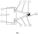
- the second motor (3) in the device proposed (figure 2) is housed in the base (1); connected with this motor, an extreme (9) of the second movable link (6) is fastened to the base (1) with the possibility of movement, and the other extreme (8) of the first movable link (5) is joined to the working element (4).
- This kinematic train provides the possibility of situating both motors in the base (both motors are stationary with respect to the base), in order to reduce the energy consumption and increase the speed simultaneously, in exchange for diminishing the mass of the moving parts.
- the kinematic train proposed is closed (the movable links, together with the base form a triangle which is a rigid construction), which increases the stiffness in the anchoring of the working element with regard to the base and additionally reduces the mass of the moving parts.
- the job of the handler is carried out in the following manner: For movements of the working element parallel to the base, both motors start up at the same time with the same speed (it is understood that the transmission ratio in the kinematic train "motor-movable link" is the same for both motors and the lengths of both movable links are equal; if either of these conditions is not met, the speed of the motors has to be different).
- connection between the working element and one of the movable links can be implemented by means of a ball or flat articulation and the connection with the other movable link can be rigid.
- the working element shall maintain its angular position with respect to one of the movable links during the movement.
- the connection between the working element and both movable links can be implemented by means of a ball or flat articulation. In this case the working element shall be unable to maintain its angular position with respect to the movable links during the movement.
- the lengths of the movable links can be different, however it is preferable they be identical (in this case it is easier to move the working element over the required trajectory).
- the connection between the base and an extreme of the movable links can be made in such a manner that it permits the movement of these extremes over an arbitrary trajectory. Notwithstanding, it is preferable that the movement of these extremes be over trajectories situated over parallel lines or over a same straight line. In this case it is easier to move the working element along the required trajectory.
- the device proposed it is desirable (but not mandatory) to make a kinematic connection between at least one of the motors and the corresponding movable link with a self-blocking transmission (for example with the aid of a nut and spindle assembly). In that case it is possible to disconnect the motors when the device is stopped and the working element can maintain its position due to the self-blocking effect. This shall permit a reduction in energy consumption.
- the device proposed it is desirable to have an articulated union between the motors and the movable links in the kinematic train, it is possible to employ additional elements - guide rails. In the case of there being various working elements (various devices) on the same base, the lengths of the movable links could be equal.
- the lengths of the movable links corresponding to a working element are greater than those corresponding to the other working element. This permits the working zone to be enlarged (area which the working element can reach) because during the movement of one working element, the other shall be unable to hinder the first. This is especially important for walking robots for which it is possible to organise the movement of each working element (robot legs) over the entire base.
- connection between the base and the first extremes of the corresponding movable links is made such that the movement trajectories of the extremes of the movable links corresponding to the first working element and the movement trajectories of the extremes of the movable links corresponding to the second working element are situated on parallel lines.
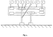
- An example of a transmission application for a four-legged robot is shown in figures 3 and 4.
Landscapes
- Engineering & Computer Science (AREA)
- Mechanical Engineering (AREA)
- Robotics (AREA)
- Manipulator (AREA)
Abstract
A working element with two degrees of mobility, which,
with the assistance of two motors manages to move two
movable links, one of them acting on the working element,
this is a method which is distinguished in the
simultaneous action on a working element with the
assistance of another movable link.
The guidance of a working element with two degrees of
mobility which has two motors one of which is housed in
the base and connected kinematically with an extreme of
the first movable link located in the base with
possibility of movement and the other motor connected
kinematically with an extreme of the second movable link,
and the working element which is connected with the other
extreme of the second movable link.
Description
- The invention pertains to the mechanical engineering sector, and in particular can be used in robotics, in Cartesian desks and other devices.
- In known technical solutions [1-5], the following is habitually employed.
The handler which is known, with two degrees of mobility, (figure 1) has two motors (2,3) one of which (2) is housed in the base and is kinematically connected with an extreme of the first movable link (5) housed in the base (1), with possibility of movement, and the other motor (3) is kinematically connected with an extreme of the second movable link (9) and the working element (4), which is connected with the other extreme (10) of the second movable link (6).
In this technical solution, the second motor (3) is fastened to the other extreme of the first movable link (5).
The drawbacks of this construction concern the fact that the second motor is mobile (during the movement of the first movable link this motor is in motion) which increases the mass of the parts in movement. This also reduces the speed and has an unnecessary energy consumption. In addition, the device known has an open kinematic train which leads to deficiencies in the stiffness of the construction and as a result thereof the need to augment the mass to improve this stiffness. -
- Patent number: EP 0320498
- Publication date: 1989-06-14
- Inventor(s): WINTER ALFRED ING; SCHENDL ADOLF DIPL-ING EC Classification: B25J9/02B2 ; B25J18/02 ; B25J19/00D2 ; B23Q1/40 ; B23Q1/62A5 ; B23Q1/00B2 ; B23Q11/00C
-
-
- Patent number: EP0546592
- Publication date: 1993-06-16
- Inventor(s): VIVIER YVES CHARLES BERNARD (FR); FAYEL EC Classification: B25J9/00H1 ; B25J9/02B
-
-
- Patent number: EP0574330 A1 931215
- Publication date: 1995-03-21
- Inventor(s): LAVALLEE STEPHANE (FR); TROCCAZ JOCELYNE (FR)
- EC Classification: G05B19/423
-
-
- Patent number: EP 0401751
- Publication date: 1990-12-12
- Inventor(s): PARIS LUIGI (IT)
- EC Classification: B62D57/024
-
-
- Patent number: EP 0672507
- Publication date: 1995-09-20
- Inventor(s): SNELL JOHN-ERIC (SE)
- EC Classification: B25J9/16L6
-
- The method of displacement of a working element with two degrees of mobility, which, with the assistance of two motors manages to move two movable links, one of them acting on the working element, this is a method which is distinguished in the simultaneous action on a working element with the assistance of another movable link. The guidance of a working element with two degrees of mobility which has two motors one of which is housed in the base and connected is kinematically with an extreme of the first link located in the base with possibility of movement and another motor connected kinematically with an extreme of the second movable link, and the working element which is connected with the other extreme of the second movable link, this guidance is that which is distinguished in the fact that the second motor is housed in the base and an extreme of the second movable link connected with this motor is stiffened in the base with possibility of movement and the other extreme of the first movable link is connected with the working element.
- The purpose of the invention is to augment the stiffness of the construction, reduce its mass, reduce the energy consumption and increase the speed.
To achieve this purpose, the second motor (3) in the device proposed (figure 2) is housed in the base (1); connected with this motor, an extreme (9) of the second movable link (6) is fastened to the base (1) with the possibility of movement, and the other extreme (8) of the first movable link (5) is joined to the working element (4).
This kinematic train provides the possibility of situating both motors in the base (both motors are stationary with respect to the base), in order to reduce the energy consumption and increase the speed simultaneously, in exchange for diminishing the mass of the moving parts. In addition, the kinematic train proposed is closed (the movable links, together with the base form a triangle which is a rigid construction), which increases the stiffness in the anchoring of the working element with regard to the base and additionally reduces the mass of the moving parts.
The job of the handler is carried out in the following manner: For movements of the working element parallel to the base, both motors start up at the same time with the same speed (it is understood that the transmission ratio in the kinematic train "motor-movable link" is the same for both motors and the lengths of both movable links are equal; if either of these conditions is not met, the speed of the motors has to be different). As long as the distance between the extremes of the movable links does not vary, the angles of the triangle "base - first movable link - second movable link" do not change, the triangle moves along the base together with the working element. The change of direction of rotation of the motors permits the working element to be moved in similar form, but in the opposite direction.
For movements of the working element perpendicular to the base, both motors have to turn in different directions with equal speed (it is understood that the transmission ratio in the kinematic train "motor-movable link" is the same for the motors, and the lengths of the two movable links are equal; if either of these conditions is not met, the speed of the motors has to be different). As long as the distance between the extremes of the movable links diminishes, the angle at the vertex of the triangle "base - first movable link - second movable link" is decreasing (the triangle continues to be isosceles). This leads to an increase in the height of the triangle and a movement of the working element perpendicular to the base. The movement in reverse of the working element is fulfilled in a similar manner by changing the direction of rotation of each motor.
For movements of the working element in an arbitrary manner, the motors must start at a different speed (the direction of rotation can be the same or in opposition, depending on the required direction of the movement of the working element). - It is to be pointed out that in the construction proposed, it is particularly easy to execute movements of the working element parallel to the base. In contrast to known constructions, during their movement, both motors apply forces favouring the movement whereby the forces are added. The control algorithm is also very simple, it is necessary to maintain the motor speeds equal. This is why the use of this handler is especially effective for walking robots, which usually move in one direction generally, and only occasionally have to turn in order to move in a perpendicular direction.
-
- Figure 1.
- The known guidance of movement of the link with two degrees of mobility.
- Figure 2.
- The proposed guidance of movement of the link with two degrees of mobility.
- Figure 3.
- Example of embodiment of the proposed guidance - the walking robot, in which four proposed guidance arrangements are being employed (viewed from above).
- Figure 4.
- Example of embodiment of the proposed guidance - the walking robot, in which four proposed guidance arrangements are being employed (viewed from the side).
- List of the numbering references of the elements shown in the Figures.
- 1. The base of the guidance arrangement
- 2. The first motor
- 3. The second motor
- 4. The working element
- 5. The first movable link
- 6. The second movable link
- 7. The first extreme of the first movable link
- 8. The second extreme of the first movable link
- 9. The first extreme of the second movable link
- 10.The second extreme of the second movable link
- 11.The foot of the robot with the guidance for vertical. movement (this guidance is not shown in the drawing).
-
- In the device proposed, the connection between the working element and one of the movable links can be implemented by means of a ball or flat articulation and the connection with the other movable link can be rigid. In this case the working element shall maintain its angular position with respect to one of the movable links during the movement.
In the device proposed, the connection between the working element and both movable links can be implemented by means of a ball or flat articulation. In this case the working element shall be unable to maintain its angular position with respect to the movable links during the movement.
In the device proposed, when there exists an articulated union between the working element and both movable links, there could be an additional spring (or springs), one of its extremes connected with a movable link, the other extreme connected with the other link and its intermediate point connected with the working element. In such a case, if there are no external forces acting on the working element, the latter shall maintain its angular position with respect to the base. If external forces act on the working element, the latter can change its angular position relative to the base, but when these forces cease to act, the working element shall recuperate its angular position with respect to the base. This is important, especially when the operation is utilised for the horizontal actuation of the leg of a walking robot. - In the device proposed, the lengths of the movable links can be different, however it is preferable they be identical (in this case it is easier to move the working element over the required trajectory).
In the device proposed, the connection between the base and an extreme of the movable links can be made in such a manner that it permits the movement of these extremes over an arbitrary trajectory. Notwithstanding, it is preferable that the movement of these extremes be over trajectories situated over parallel lines or over a same straight line. In this case it is easier to move the working element along the required trajectory.
In the device proposed it is desirable (but not mandatory) to make a kinematic connection between at least one of the motors and the corresponding movable link with a self-blocking transmission (for example with the aid of a nut and spindle assembly). In that case it is possible to disconnect the motors when the device is stopped and the working element can maintain its position due to the self-blocking effect. This shall permit a reduction in energy consumption.
In the device proposed it is desirable to have an articulated union between the motors and the movable links in the kinematic train, it is possible to employ additional elements - guide rails.
In the case of there being various working elements (various devices) on the same base, the lengths of the movable links could be equal. However the most interesting case arises when for at least two working elements, the lengths of the movable links corresponding to a working element are greater than those corresponding to the other working element. This permits the working zone to be enlarged (area which the working element can reach) because during the movement of one working element, the other shall be unable to hinder the first. This is especially important for walking robots for which it is possible to organise the movement of each working element (robot legs) over the entire base.
For at least two working elements the connection between the base and the first extremes of the corresponding movable links is made such that the movement trajectories of the extremes of the movable links corresponding to the first working element and the movement trajectories of the extremes of the movable links corresponding to the second working element are situated on parallel lines. An example of a transmission application for a four-legged robot is shown in figures 3 and 4.
Claims (11)
- Method of displacement of a working element with two degrees of mobility, which, with aid of two motors manages to move two movable links, one of them acting on a working link, characterised in that there exists simultaneous action on a working element with aid of another movable link.
- Guidance of a working element with two degrees of mobility which has two motors one of which is housed in a base and connected kinematically with an extreme of a first movable link located in the base with possibility of movement and another motor connected kinematically with an extreme of a second movable link, and a working element which is connected with. other extreme of the second movable link, characterised in that the second motor is housed in the base and an extreme of the second movable link connected with this motor is stiffened in the base with possibility of movement and the other extreme of the first movable link is connected with the working element.
- Guidance of a working element with two degrees of mobility, according to claim 2, characterised in that a connection between the working element and one of the movable links is implemented with aid of an articulation.
- Guidance of a working element with two degrees of mobility, according to claims 2 and 3, characterised in that the connection between the working element and the two movable links is implemented with aid of an articulation.
- Guidance of a working element with two degrees of mobility, according to claim 4, characterised in that the connection between the working element and the movable links has additionally a spring.
- Guidance of a working element with two degrees of mobility, according to any of claims 2 to 5, characterised in that lengths of the movable links are equal.
- Guidance of a working element with two degrees of mobility, according to any of claims 2 to 5, characterised in that the connection between the base and an extreme of the movable links is achieved in such a manner that it permits a movement in coincident trajectories over parallel lines.
- Guidance of a working element with two degrees of mobility, according to any of claims 2 to 6, characterised in that the connection between the base and an extreme of the movable links is achieved in such a manner that it permits movement of these extremes along trajectories which are situated over a same straight line.
- Guidance of a working element with two degrees of mobility, according to any of claims 2 to 8, characterised in that the kinematic connection between at least one of the motors and its corresponding movable link is self-blocking.
- Guidance of a working element with two degrees of mobility, according to any of claims 2 to 9, characterised in that by using different working elements in a same base, for at least two of them, the lengths of the movable links corresponding to one of the working elements are larger than the lengths of the movable links corresponding to another working element.
- Guidance of a working element with two degrees of mobility, according to claim 10, characterised in that for at least two working elements, the connection between the base and an extreme of the movable links is achieved in such a manner that trajectories of movement of the extremes of the movable links corresponding to a first working element and the trajectories of movement of the extremes of the movable links corresponding to a second working element, are situated on parallel lines.
Applications Claiming Priority (3)
| Application Number | Priority Date | Filing Date | Title |
|---|---|---|---|
| ES009902863A ES2161184B1 (en) | 1999-12-28 | 1999-12-28 | A DEVICE OF A WORKING ELEMENT WITH TWO DEGREES OF MOBILITY. |
| ES9902863 | 1999-12-28 | ||
| PCT/ES2000/000484 WO2001047734A1 (en) | 1999-12-28 | 2000-12-22 | Device for a work element having two degrees of mobility |
Publications (1)
| Publication Number | Publication Date |
|---|---|
| EP1203682A1 true EP1203682A1 (en) | 2002-05-08 |
Family
ID=8311097
Family Applications (1)
| Application Number | Title | Priority Date | Filing Date |
|---|---|---|---|
| EP00985275A Withdrawn EP1203682A1 (en) | 1999-12-28 | 2000-12-22 | Device for a work element having two degrees of mobility |
Country Status (5)
| Country | Link |
|---|---|
| US (1) | US6952978B2 (en) |
| EP (1) | EP1203682A1 (en) |
| AU (1) | AU2174201A (en) |
| ES (1) | ES2161184B1 (en) |
| WO (1) | WO2001047734A1 (en) |
Families Citing this family (4)
| Publication number | Priority date | Publication date | Assignee | Title |
|---|---|---|---|---|
| US20050048366A1 (en) * | 2003-08-27 | 2005-03-03 | Bowden William L. | Cathode material and method of manufacturing |
| ES2244343B1 (en) * | 2004-05-31 | 2007-03-01 | Consejo Sup. Investig. Cientificas | QUADRUPED ROBOT FOR TECHNOLOGICAL PROCESSES. |
| US20090088912A1 (en) * | 2007-09-28 | 2009-04-02 | Anorad Corporation | Linear driven x-z robot |
| JP6684439B2 (en) * | 2016-03-30 | 2020-04-22 | 日本電産株式会社 | robot |
Family Cites Families (17)
| Publication number | Priority date | Publication date | Assignee | Title |
|---|---|---|---|---|
| US4256947A (en) * | 1977-06-06 | 1981-03-17 | Ettore De Candia | Car body welding assembly system |
| DE3404553C2 (en) * | 1984-02-09 | 1986-04-17 | Carl Hurth Maschinen- und Zahnradfabrik GmbH & Co, 8000 München | Handling device, in particular for loading and unloading machine tools |
| EP0320498A3 (en) | 1985-07-25 | 1991-10-09 | Alfred Winter | Industrial robot |
| FR2621715B1 (en) * | 1987-10-13 | 1991-11-15 | Ensait | MECHANICAL SCANNING DEVICE |
| IT1230248B (en) | 1989-06-08 | 1991-10-18 | Luigi Paris | CLIMBING ROBOT, MOBILE ALONG A TRUSS STRUCTURE, IN PARTICULAR OF A HIGH VOLTAGE ELECTRIC LINE POLE. |
| JPH03208580A (en) * | 1989-10-03 | 1991-09-11 | Yaskawa Electric Mfg Co Ltd | Manipulator using face pulse motor |
| US4962676A (en) * | 1989-10-12 | 1990-10-16 | The Gillette Company | Two axis transfer device |
| FR2682909B1 (en) | 1991-10-25 | 1994-01-28 | Arilon | HIGH-RATE INDUSTRIAL ROBOT FOR MOVING A TOOL FOLLOWING THE THREE AXES OF AN ORTHOGONAL CARTESIAN MARK. |
| FR2691093B1 (en) | 1992-05-12 | 1996-06-14 | Univ Joseph Fourier | ROBOT FOR GUIDANCE OF GESTURES AND CONTROL METHOD. |
| JPH06132380A (en) * | 1992-09-04 | 1994-05-13 | Fujitsu Ltd | Transfer device |
| US5340400A (en) * | 1993-02-04 | 1994-08-23 | Megamation Incorporated | Linear motor surface coating system |
| SE9400579L (en) | 1994-02-21 | 1995-08-22 | Asea Brown Boveri | Procedure for controlling the movement of an industrial robot in and around singularities |
| JP3117118B2 (en) * | 1995-07-31 | 2000-12-11 | ヒーハイスト精工株式会社 | Multi-degree-of-freedom positioning mechanism |
| CA2181097C (en) * | 1996-07-12 | 2007-10-23 | Fernando Manuel Rodrigues Nunes | Overload protector for robotic tooling |
| US5886494A (en) * | 1997-02-06 | 1999-03-23 | Camelot Systems, Inc. | Positioning system |
| JP3806812B2 (en) * | 1997-07-16 | 2006-08-09 | 株式会社ダイヘン | 2-arm type transfer robot |
| ATE216939T1 (en) * | 1997-10-20 | 2002-05-15 | Hueller Hille Gmbh | MACHINE TOOL FOR 3-AXIS PROCESSING OF WORKPIECES |
-
1999
- 1999-12-28 ES ES009902863A patent/ES2161184B1/en not_active Expired - Fee Related
-
2000
- 2000-12-22 WO PCT/ES2000/000484 patent/WO2001047734A1/en not_active Ceased
- 2000-12-22 AU AU21742/01A patent/AU2174201A/en not_active Abandoned
- 2000-12-22 US US09/914,432 patent/US6952978B2/en not_active Expired - Fee Related
- 2000-12-22 EP EP00985275A patent/EP1203682A1/en not_active Withdrawn
Non-Patent Citations (1)
| Title |
|---|
| See references of WO0147734A1 * |
Also Published As
| Publication number | Publication date |
|---|---|
| ES2161184A1 (en) | 2001-11-16 |
| WO2001047734A1 (en) | 2001-07-05 |
| ES2161184B1 (en) | 2002-07-01 |
| US20020134188A1 (en) | 2002-09-26 |
| AU2174201A (en) | 2001-07-09 |
| US6952978B2 (en) | 2005-10-11 |
| WO2001047734A8 (en) | 2002-03-21 |
Similar Documents
| Publication | Publication Date | Title |
|---|---|---|
| US4628765A (en) | Spherical robotic wrist joint | |
| US8498741B2 (en) | Dexterous humanoid robotic wrist | |
| US20080282821A1 (en) | Robot with linearly movable support member attaching to gripper | |
| US20020015624A1 (en) | Parallel structure of a spatial 3-axis machine tool with three degrees-of-freedom | |
| US6952978B2 (en) | Device for a work element having two degrees of mobility | |
| US10449669B2 (en) | Manipulator mechanism | |
| Cai et al. | A study on the kinematics and dynamics of a 3-DOF parallel machine tool | |
| KR20200049117A (en) | Humanoid robot | |
| CN109848969B (en) | Decoupling three-rotational-freedom parallel mechanism for virtual-axis machine tool and robot | |
| CN1178769C (en) | 3-TRT/SPS four-degree-of-freedom space parallel robot mechanism | |
| CN112296992A (en) | Rope-driven multi-joint robot unit mechanism | |
| CN110281224A (en) | A kind of 3DOF robot parallel mechanism | |
| CN106625591B (en) | Three-translation two-rotation five-degree-of-freedom parallel mechanism | |
| CN116922424B (en) | A flexible cable fully driven humanoid dexterous hand finger mechanism | |
| Neugebauer et al. | New approaches to machine structures to overcome the limits of classical parallel structures | |
| CA1074832A (en) | Cooperative drive robot | |
| CN111017061B (en) | A transmission pole tower climbing robot, system and method | |
| RU2288091C2 (en) | Method for operating two-coordinate five-hinged manipulator | |
| CN214518061U (en) | Eight-axis operation structure of inverted welding robot | |
| KR100225975B1 (en) | A jointing structure of an arm for a vertical joint multi-nuckle robot | |
| CN106826767B (en) | Six-degree-of-freedom parallel mechanism based on grabbing parallel structure | |
| CN107283387A (en) | A kind of robot | |
| CN101590646A (en) | Aerial Cable Climbing Robot Walking and Obstacle-Crossing Mechanism | |
| KR20230101735A (en) | Parallel mechanism apparatus with | |
| JPH1029178A (en) | Manipulator |
Legal Events
| Date | Code | Title | Description |
|---|---|---|---|
| PUAI | Public reference made under article 153(3) epc to a published international application that has entered the european phase |
Free format text: ORIGINAL CODE: 0009012 |
|
| 17P | Request for examination filed |
Effective date: 20010924 |
|
| AK | Designated contracting states |
Kind code of ref document: A1 Designated state(s): AT BE CH CY DE DK ES FI FR GB GR IE IT LI LU MC NL PT SE TR |
|
| AX | Request for extension of the european patent |
Free format text: AL;LT;LV;MK;RO;SI |
|
| RBV | Designated contracting states (corrected) |
Designated state(s): DE FR GB GR IT SE |
|
| STAA | Information on the status of an ep patent application or granted ep patent |
Free format text: STATUS: THE APPLICATION IS DEEMED TO BE WITHDRAWN |
|
| 18D | Application deemed to be withdrawn |
Effective date: 20040701 |