EP1203592A1 - Blood conditioning device - Google Patents
Blood conditioning device Download PDFInfo
- Publication number
- EP1203592A1 EP1203592A1 EP01125951A EP01125951A EP1203592A1 EP 1203592 A1 EP1203592 A1 EP 1203592A1 EP 01125951 A EP01125951 A EP 01125951A EP 01125951 A EP01125951 A EP 01125951A EP 1203592 A1 EP1203592 A1 EP 1203592A1
- Authority
- EP
- European Patent Office
- Prior art keywords
- blood
- flow
- bubbles
- section
- particles
- Prior art date
- Legal status (The legal status is an assumption and is not a legal conclusion. Google has not performed a legal analysis and makes no representation as to the accuracy of the status listed.)
- Granted
Links
Images


Classifications
-
- B—PERFORMING OPERATIONS; TRANSPORTING
- B01—PHYSICAL OR CHEMICAL PROCESSES OR APPARATUS IN GENERAL
- B01D—SEPARATION
- B01D19/00—Degasification of liquids
- B01D19/0042—Degasification of liquids modifying the liquid flow
- B01D19/0052—Degasification of liquids modifying the liquid flow in rotating vessels, vessels containing movable parts or in which centrifugal movement is caused
- B01D19/0057—Degasification of liquids modifying the liquid flow in rotating vessels, vessels containing movable parts or in which centrifugal movement is caused the centrifugal movement being caused by a vortex, e.g. using a cyclone, or by a tangential inlet
-
- A—HUMAN NECESSITIES
- A61—MEDICAL OR VETERINARY SCIENCE; HYGIENE
- A61M—DEVICES FOR INTRODUCING MEDIA INTO, OR ONTO, THE BODY; DEVICES FOR TRANSDUCING BODY MEDIA OR FOR TAKING MEDIA FROM THE BODY; DEVICES FOR PRODUCING OR ENDING SLEEP OR STUPOR
- A61M1/00—Suction or pumping devices for medical purposes; Devices for carrying-off, for treatment of, or for carrying-over, body-liquids; Drainage systems
- A61M1/36—Other treatment of blood in a by-pass of the natural circulatory system, e.g. temperature adaptation, irradiation ; Extra-corporeal blood circuits
- A61M1/3601—Extra-corporeal circuits in which the blood fluid passes more than once through the treatment unit
- A61M1/3603—Extra-corporeal circuits in which the blood fluid passes more than once through the treatment unit in the same direction
-
- A—HUMAN NECESSITIES
- A61—MEDICAL OR VETERINARY SCIENCE; HYGIENE
- A61M—DEVICES FOR INTRODUCING MEDIA INTO, OR ONTO, THE BODY; DEVICES FOR TRANSDUCING BODY MEDIA OR FOR TAKING MEDIA FROM THE BODY; DEVICES FOR PRODUCING OR ENDING SLEEP OR STUPOR
- A61M1/00—Suction or pumping devices for medical purposes; Devices for carrying-off, for treatment of, or for carrying-over, body-liquids; Drainage systems
- A61M1/36—Other treatment of blood in a by-pass of the natural circulatory system, e.g. temperature adaptation, irradiation ; Extra-corporeal blood circuits
- A61M1/3621—Extra-corporeal blood circuits
- A61M1/3627—Degassing devices; Buffer reservoirs; Drip chambers; Blood filters
-
- A—HUMAN NECESSITIES
- A61—MEDICAL OR VETERINARY SCIENCE; HYGIENE
- A61M—DEVICES FOR INTRODUCING MEDIA INTO, OR ONTO, THE BODY; DEVICES FOR TRANSDUCING BODY MEDIA OR FOR TAKING MEDIA FROM THE BODY; DEVICES FOR PRODUCING OR ENDING SLEEP OR STUPOR
- A61M2205/00—General characteristics of the apparatus
- A61M2205/75—General characteristics of the apparatus with filters
- A61M2205/7545—General characteristics of the apparatus with filters for solid matter, e.g. microaggregates
Definitions
- the present invention relates generally to the extracorporeal circulation of blood during open heart surgery, and more particularly to a device for conditioning blood prior to returning the blood to the patient.
- Open heart surgery is performed on a "still" heart.
- the patient's blood is circulated by an extracorporeal system, which includes a blood pump, a cardiotomy reservoir and an oxygenator.
- blood is drawn from the patient and pumped through the oxygenator and then returned to the patient.
- blood is scavenged from the surgical site and this recovered blood is added to the system through the cardiotomy reservoir.
- surgical debris and air bubbles may be introduced into the system at this point and it is important that the particulate debris and bubbles not be administered to the patient.
- the size of the physical membrane of the arterial filter is very large to provide a margin of safety.
- this increases the surface area in contact with blood which is undesirable and increases priming volume which is undesirable.
- the mesh size of a typical filter is inadequate to capture small bubbles. Consequently the conventional arterial filter is not efficient at handling bubbles and it is improperly sized for the typical particulate load.
- the blood conditioning device has two main connections. There is a blood input port and a blood output port. A third connection is used to purge or prime the device. In some embodiments of the device this line is always open and is used for continuous recirculation of blood containing bubble to the cardiotomy reservoir.
- the blood conditioning device relies on a first dynamic stage to remove bubbles from the mixed flow of bubbles and particles in blood.
- the dynamic stage passes the bubble free but particle laden blood flow to a second mechanical filter media stage where the particles are trapped.
- the gas bubbles maybe collected and retained in the device or returned with a modest blood flow to the cardiotomy reservoir through the third purge or recirculation connection.
- the blood conditioning device is disposable and used once. The particulate debris is retained in the device and discarded at the conclusion of the procedure.
- the blood is delivered to a blood centrifuge section, which imparts a strong radial acceleration to the blood flow.
- the pressure gradient is created by forcing the blood along a helical flow path.
- the radial acceleration causes bubbles both large and small to migrate toward the center streamline of the flow.
- a bubble pick up may be placed in the zone where the bubbles accumulate.
- the bubble pick up collects the bubbles and it is connected to the cardiotomy reservoir to extract the bubbles from the device.
- This dynamic stage is referred to as the "helix" in the description.
- a momentary operation valve is placed on top of the device.
- the preferred versions of this valve opens side holes in the bubble pick up tube in order to release gross air from the device to the cardiotomy reservoir.
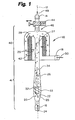
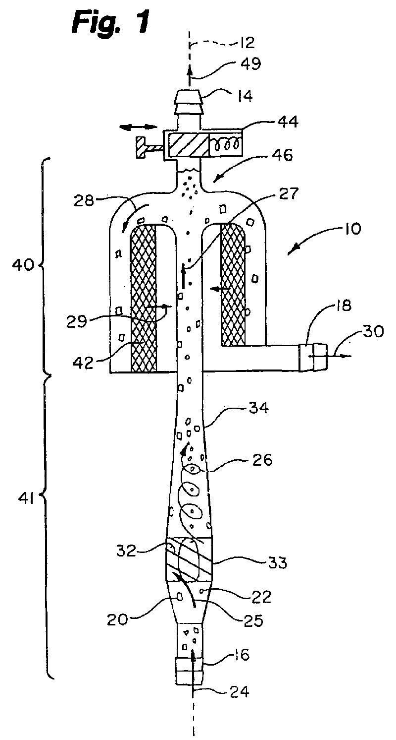
- Fig.1 shows a first embodiment of the blood conditioning device 10.
- This representative device is shown in a schematic cross section and it is generally symmetric about axis 12. In use this device is mounted vertically with the purge/recirculation port 14 located at the "top".
- the device can be used for conditioning blood in any perfusion circuit it is preferred to couple the input port 16 to the source of blood and to connect the output port 18 directly to the cannula used to deliver blood to the patient.
- the blood pump supplies the modest pressure difference required to operate the device.
- the oxygenator and cardiotomy reservoir are of conventional design and they are used in the conventional fashion.
- the small squares typified by square 20 represent surgical debris with a density slightly greater than blood.
- the small circles typified by circle 22 represent bubbles or micro bubbles in the blood flow 24.
- the bubbles have a size of approximately 40mu or more and micro-bubbles have a diameter of 40mu or less.
- the blood flow 24 has a uniform distribution of particles and bubbles in the input stream, and is called a "mixed blood flow " herein.
- the mixed blood flow 25 enters an acceleration chamber or "helix " 33"of the dynamic section 41.
- One or more blades 32 form a helical flow path in the acceleration chamber 33.
- the blood flow, which leaves the helix 33 has a spiral motion as indicated by blood flow arrow 26.
- the radial acceleration is strong enough to cause the bubbles to accumulate along the centerline or axis 12 of the device 10.
- the length of the discharge tube 34 is sufficiently long to permit nearly complete separation of the bubbles from the particles. In this first embodiment of the device these bubbles coalesce and migrate toward zone 46.
- the blood now free of bubbles enters a flow path that intercepts a membrane 42.
- the annular membrane 42 filters the blood flow and the particles adheres to the surface of the membrane while the blood passes through the membrane as depicted by blood flow 29.
- the blood accumulated behind the membrane 42 is delivered to the output port 18 and the now conditioned blood flow 30 is introduced into the patient.
- the purge stopcock 44 may be used to prime the device during setup and may be used to periodically return the bubble rich accumulated volume 46 to the blood cardiotomy reservoir during operation.
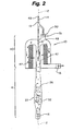
- Fig. 2 is a schematic cross section of a second embodiment of the blood conditioning device 10.
- a bubble pick off tube 48 is positioned to intercept the stream of micro-bubbles from the dynamic section 41.
- the opening 47 of the bubble pick off tube 48 is sized to capture the blood flow near the centerline 12 of the dynamic section.
- the opening 47 establishes a small regulated blood flow 49 from the device to the cardiotomy reservoir (not shown) which carries the bubbles back to the cardiotomy reservoir.
- This recirculation line 13 is always open.
- Fig. 3 is an alternate embodiment incorporating a bubble pick off 48 which pulls bubbles from the device through opening 47.
- this device operates similar to figure 2 but in contrast the particles can directly engage the filter mesh 42 as the blood flow flows in an outward direction from the center of the device.
- Fig. 3 also shows the preferred form of momentary operation valve 50.
- the momentary operation valve 50 is provided at the top of the housing to allow the user to purge or prime the device. When "open” the valve 50 allows the gross air from the interior volume of the device to be purged into the cardiotomy reservoir. When closed the interior volume of the device is closed off but the bubble pick off tube remains open to the cardiotomy reservoir.
- the preferred form of the valve includes a ring 51 which can slide between two positions. In the first position the ring covers side holes 47 in the bubble pick up tube 48 and is in the "dosed” position. The valve 50 in Fig. 7A is shown in this state. In the second “open “ position the ring 51 uncovers the side holes 47 in the bubble pick off tube 48 as seen in the Fig. 3 among others. In the "open” position the interior volume of the housing 13 is open to the reservoir.
- This valve may be operated to bleed the system both prior to use and during a surgery.
- the valve 50 is closed and remains open only while operated by the perfusionist.
- Fig. 4 is an alternate embodiment of the invention which includes a diverging channel 53 to decrease the velocity of the blood flow after the bubbles have been picked off at opening 47. It is expected to be advantageous to decrease the velocity in the mechanical filtration section 40.
- Fig. 5 is an alternate embodiment of the device having a "side by side” configuration the dynamic section 41 located substantially next tot he mechanical filtration section 40.
- the principle advantage of this configuration is the ability to see the bubble pick off 48 and related area of the dynamic section during operation and provides more options for flow dynamic optimization in the two sections.
- Fig. 6A is side elevation of an alternate embodiment of the device.
- the device is very compact.
- the particles 20 are captured on the outer surface of the annular filter mesh 42.while the bubbles pass the helix 33 in advance and are picked up in line 48.
- the preferred momentary operation valve 50 is schematically shown, opening side hole to the recirculation line to release gross air upon operation.
- Fig. 6B is top view of an alternate embodiment of the device. In this view one can see that the helix 33 is located in a circular flow path. In general the input mixed blood flow 24 turns through about 90 degrees before it enters the helix 33.
- the dynamic section 41 extends around the circle and the bubble pick off 48 is downstream through another 90 degrees of turning.
- Fig. 7A is side elevation of an alternate embodiment of the device.
- the blood flow carrying particulates is from the interior of the device to the exterior as typified by the location of particle 20.
- embossment conical surface or funnel is used to accelerate blood flow as it enters the filter zone.
- Fig. 7B is top view of an alternate embodiment of the device.
- the helix 33 is located part way round the circumference of the device with a bubble pick off 48 located downstream of the helix 33.
Landscapes
- Health & Medical Sciences (AREA)
- Vascular Medicine (AREA)
- Heart & Thoracic Surgery (AREA)
- Biomedical Technology (AREA)
- Life Sciences & Earth Sciences (AREA)
- Veterinary Medicine (AREA)
- Engineering & Computer Science (AREA)
- Anesthesiology (AREA)
- Public Health (AREA)
- Hematology (AREA)
- Cardiology (AREA)
- Animal Behavior & Ethology (AREA)
- General Health & Medical Sciences (AREA)
- Chemical & Material Sciences (AREA)
- Chemical Kinetics & Catalysis (AREA)
- External Artificial Organs (AREA)
- Separation Using Semi-Permeable Membranes (AREA)
Abstract
Description
- The present invention relates generally to the extracorporeal circulation of blood during open heart surgery, and more particularly to a device for conditioning blood prior to returning the blood to the patient.
- Open heart surgery is performed on a "still" heart. The patient's blood is circulated by an extracorporeal system, which includes a blood pump, a cardiotomy reservoir and an oxygenator. In operation, blood is drawn from the patient and pumped through the oxygenator and then returned to the patient. In many instances blood is scavenged from the surgical site and this recovered blood is added to the system through the cardiotomy reservoir. As a consequence, surgical debris and air bubbles may be introduced into the system at this point and it is important that the particulate debris and bubbles not be administered to the patient.
- It is the conventional standard of care to place a so-called "arterial filter" in the blood line to intercept and capture particles and gas bubbles before the blood is returned to the patient's body. Filters of this type capture both gas bubbles and particles on a filter mesh. However conventional arterial filters are problematic. Typically the volume of an atrial filter is large to maximize the ability of the device to collect and hold gas bubbles. Captured bubbles are retained on the mesh during the entire surgical procedure. Each bubble that is retained reduces the filter mesh surface area available for particulate collection. It is possible that a large particle load will increase the pressure drop across the filter. This "clogging" effect can increase the pressure on the captured bubbles and force them though the filter. As a consequence of this problem the size of the physical membrane of the arterial filter is very large to provide a margin of safety. However this increases the surface area in contact with blood which is undesirable and increases priming volume which is undesirable. It should also be noted that the mesh size of a typical filter is inadequate to capture small bubbles. Consequently the conventional arterial filter is not efficient at handling bubbles and it is improperly sized for the typical particulate load.
- It must also be noted that blood is a very delicate organ and surface contact, turbulence and pressure drops within the system can injure the blood. These properties of blood must be accommodated as well.
- In the present invention the blood conditioning device has two main connections. There is a blood input port and a blood output port. A third connection is used to purge or prime the device. In some embodiments of the device this line is always open and is used for continuous recirculation of blood containing bubble to the cardiotomy reservoir.
- The blood conditioning device relies on a first dynamic stage to remove bubbles from the mixed flow of bubbles and particles in blood.
- The dynamic stage passes the bubble free but particle laden blood flow to a second mechanical filter media stage where the particles are trapped. The gas bubbles maybe collected and retained in the device or returned with a modest blood flow to the cardiotomy reservoir through the third purge or recirculation connection.
- The blood conditioning device is disposable and used once. The particulate debris is retained in the device and discarded at the conclusion of the procedure.
- In the first dynamic stage, the blood is delivered to a blood centrifuge section, which imparts a strong radial acceleration to the blood flow. The pressure gradient is created by forcing the blood along a helical flow path. The radial acceleration causes bubbles both large and small to migrate toward the center streamline of the flow. A bubble pick up may be placed in the zone where the bubbles accumulate. The bubble pick up collects the bubbles and it is connected to the cardiotomy reservoir to extract the bubbles from the device. In an alternate embodiment of the device there is no extraction tube or bubble pick off tube and the bubbles are allowed to coalesces and accumulate in the device during operation. This dynamic stage is referred to as the "helix" in the description.
- To purge or prime the device a momentary operation valve is placed on top of the device. The preferred versions of this valve opens side holes in the bubble pick up tube in order to release gross air from the device to the cardiotomy reservoir.
- Throughout the several figures of the drawing identical reference numerals indicate identical structure, wherein:
- Fig. 1 is a schematic cross section of a first embodiment of the device;
- Fig. 2 is a schematic cross section of a second embodiment of the device;
- Fig. 3 is a schematic cross section of a third embodiment of the device;
- Fig. 4 is a schematic cross section of a fourth embodiment of the device;
- Fig. 5 is a schematic cross section of a fifth embodiment of the device;
- Fig. 6A is a schematic cross section of a sixth embodiment of the device;
- Fig. 6B is a schematic cross section of a sixth embodiment of the device;
- Fig. 7A is a schematic cross section of a seventh embodiment of the device; and,
- Fig. 7B is a schematic cross section of a seventh embodiment of the device.
-
- Fig.1 shows a first embodiment of the
blood conditioning device 10. This representative device is shown in a schematic cross section and it is generally symmetric aboutaxis 12. In use this device is mounted vertically with the purge/recirculation port 14 located at the "top". Although the device can be used for conditioning blood in any perfusion circuit it is preferred to couple theinput port 16 to the source of blood and to connect theoutput port 18 directly to the cannula used to deliver blood to the patient. The blood pump supplies the modest pressure difference required to operate the device. The oxygenator and cardiotomy reservoir are of conventional design and they are used in the conventional fashion. - In the various figures the small squares typified by
square 20 represent surgical debris with a density slightly greater than blood. The small circles typified bycircle 22 represent bubbles or micro bubbles in theblood flow 24. The bubbles have a size of approximately 40mu or more and micro-bubbles have a diameter of 40mu or less. At theinlet port 16, theblood flow 24 has a uniform distribution of particles and bubbles in the input stream, and is called a "mixed blood flow " herein. Themixed blood flow 25 enters an acceleration chamber or "helix " 33"of thedynamic section 41. One ormore blades 32 form a helical flow path in theacceleration chamber 33. The blood flow, which leaves thehelix 33, has a spiral motion as indicated byblood flow arrow 26. The radial acceleration is strong enough to cause the bubbles to accumulate along the centerline oraxis 12 of thedevice 10. The length of thedischarge tube 34 is sufficiently long to permit nearly complete separation of the bubbles from the particles. In this first embodiment of the device these bubbles coalesce and migrate towardzone 46. - Eventually the spiral motion of the blood flow is reduced as indicated by
blood flow 27 and the bubblefree blood flow 28, leaves thedynamic section 41 and turns to enter themechanical separation section 40. - The blood now free of bubbles enters a flow path that intercepts a
membrane 42. Theannular membrane 42 filters the blood flow and the particles adheres to the surface of the membrane while the blood passes through the membrane as depicted byblood flow 29. The blood accumulated behind themembrane 42 is delivered to theoutput port 18 and the now conditionedblood flow 30 is introduced into the patient. - In operation the particles and blood turn into the
mechanical separation section 40 while the buoyancy of the bubbles causes them to coalesce into larger bubble and form a bubble rich volume orzone 46 trapped near thestopcock 44. Thepurge stopcock 44 may be used to prime the device during setup and may be used to periodically return the bubble rich accumulatedvolume 46 to the blood cardiotomy reservoir during operation. - Fig. 2 is a schematic cross section of a second embodiment of the
blood conditioning device 10. In this second embodiment a bubble pick offtube 48 is positioned to intercept the stream of micro-bubbles from thedynamic section 41. Theopening 47 of the bubble pick offtube 48 is sized to capture the blood flow near thecenterline 12 of the dynamic section. Theopening 47 establishes a smallregulated blood flow 49 from the device to the cardiotomy reservoir (not shown) which carries the bubbles back to the cardiotomy reservoir. Thisrecirculation line 13 is always open. - Fig. 3 is an alternate embodiment incorporating a bubble pick off 48 which pulls bubbles from the device through
opening 47. In this device operates similar to figure 2 but in contrast the particles can directly engage thefilter mesh 42 as the blood flow flows in an outward direction from the center of the device. - Fig. 3 also shows the preferred form of
momentary operation valve 50. Themomentary operation valve 50 is provided at the top of the housing to allow the user to purge or prime the device. When "open" thevalve 50 allows the gross air from the interior volume of the device to be purged into the cardiotomy reservoir. When closed the interior volume of the device is closed off but the bubble pick off tube remains open to the cardiotomy reservoir. - The preferred form of the valve includes a
ring 51 which can slide between two positions. In the first position the ring covers side holes 47 in the bubble pick uptube 48 and is in the "dosed" position. Thevalve 50 in Fig. 7A is shown in this state. In the second "open " position thering 51 uncovers the side holes 47 in the bubble pick offtube 48 as seen in the Fig. 3 among others. In the "open" position the interior volume of thehousing 13 is open to the reservoir. - This valve may be operated to bleed the system both prior to use and during a surgery. In general the
valve 50 is closed and remains open only while operated by the perfusionist. - Fig. 4 is an alternate embodiment of the invention which includes a diverging
channel 53 to decrease the velocity of the blood flow after the bubbles have been picked off atopening 47. It is expected to be advantageous to decrease the velocity in themechanical filtration section 40. - Fig. 5 is an alternate embodiment of the device having a "side by side" configuration the
dynamic section 41 located substantially next tot hemechanical filtration section 40. The principle advantage of this configuration is the ability to see the bubble pick off 48 and related area of the dynamic section during operation and provides more options for flow dynamic optimization in the two sections. - Fig. 6A is side elevation of an alternate embodiment of the device. In this configuration the device is very compact. In this version of the device the particles 20are captured on the outer surface of the annular filter mesh 42.while the bubbles pass the
helix 33 in advance and are picked up inline 48. On top of the device the preferredmomentary operation valve 50 is schematically shown, opening side hole to the recirculation line to release gross air upon operation. - Fig. 6B is top view of an alternate embodiment of the device. In this view one can see that the
helix 33 is located in a circular flow path. In general the input mixedblood flow 24 turns through about 90 degrees before it enters thehelix 33. - The
dynamic section 41 extends around the circle and the bubble pick off 48 is downstream through another 90 degrees of turning. - Fig. 7A is side elevation of an alternate embodiment of the device. In this embodiment in contrast to figure 6 the blood flow carrying particulates is from the interior of the device to the exterior as typified by the location of
particle 20. In this embossment conical surface or funnel is used to accelerate blood flow as it enters the filter zone. - Fig. 7B is top view of an alternate embodiment of the device. In this version of the device the
helix 33 is located part way round the circumference of the device with a bubble pick off 48 located downstream of thehelix 33.
Claims (4)
- A blood conditioning device for removing bubbles and particles from a stream containing a mixed flow having both particles and bubbles, said device comprising:a first dynamic separation section for separating bubbles from said mixed flow, generating a flow of particles and blood but free of bubbles;a second section coupled to said first section having a filter membrane arranged to intercept the flow of particles and blood generating a flow of blood free of both particles and bubbles.
- The device of claim 1 wherein said dynamic separation section includes a helical flow path for imparting rotary motion to blood flow though the section.
- A blood conditioning device comprising:a housing having a first blood inlet port, a second blood outlet port and a third purge/ recirculation port;a helical blood acceleration section coupled to said first blood inlet port for removing bubbles from the blood entering the inlet, and producing an acceleration section output flow;a mechanical filtration section coupled to said helical blood acceleration section, receiving said acceleration section output flow and for trapping particles carried by said flow producing a device output flow for a patient.
- The device of claim 3 wherein the dynamic section includes a helical flow path and a bubble pick off tube place to remove bubbles; said bubble pick off tube coupled tot he third port and having a continuous redrculation flow during operation of the device.
Applications Claiming Priority (2)
| Application Number | Priority Date | Filing Date | Title |
|---|---|---|---|
| US24620000P | 2000-11-06 | 2000-11-06 | |
| US246200P | 2000-11-06 |
Publications (2)
| Publication Number | Publication Date |
|---|---|
| EP1203592A1 true EP1203592A1 (en) | 2002-05-08 |
| EP1203592B1 EP1203592B1 (en) | 2004-09-22 |
Family
ID=22929684
Family Applications (1)
| Application Number | Title | Priority Date | Filing Date |
|---|---|---|---|
| EP01125951A Expired - Lifetime EP1203592B1 (en) | 2000-11-06 | 2001-10-31 | Blood conditioning device |
Country Status (5)
| Country | Link |
|---|---|
| EP (1) | EP1203592B1 (en) |
| JP (1) | JP2002177384A (en) |
| AT (1) | ATE276780T1 (en) |
| DE (1) | DE60105738T2 (en) |
| ES (1) | ES2228727T3 (en) |
Cited By (5)
| Publication number | Priority date | Publication date | Assignee | Title |
|---|---|---|---|---|
| EP1557186A1 (en) * | 2004-01-20 | 2005-07-27 | Sorin Group Deutschland GmbH | Automatic air removal system |
| WO2006030263A1 (en) * | 2004-09-17 | 2006-03-23 | Gambro Lundia Ab | A blood chamber for an extracorporeal circuit |
| ITMO20110161A1 (en) * | 2011-06-27 | 2012-12-28 | Eurosets Srl | FILTERING DEVICE OF ARTERIAL BLOOD |
| FR3012976A1 (en) * | 2013-11-12 | 2015-05-15 | Biocarecell | DEVICE FOR FILTRATION OF BIOLOGICAL FLUID. |
| RU2815528C1 (en) * | 2023-10-30 | 2024-03-18 | Федеральное государственное бюджетное учреждение "Национальный медицинский исследовательский центр трансплантологии и искусственных органов имени академика В.И. Шумакова" Министерства здравоохранения Российской Федерации (ФГБУ "НМИЦ ТИО им. академика В.И. Шумакова" Минздрава России) | Air separator for extracorporeal circulation system |
Families Citing this family (2)
| Publication number | Priority date | Publication date | Assignee | Title |
|---|---|---|---|---|
| FR2931079B1 (en) * | 2008-05-13 | 2010-07-30 | Commissariat Energie Atomique | DEVICE AND METHOD FOR SEPARATING A SUSPENSION |
| DE102019131140A1 (en) | 2019-11-19 | 2021-05-20 | B.Braun Avitum Ag | Blood line system for an extracorporeal blood treatment machine and extracorporeal blood treatment machine |
Citations (3)
| Publication number | Priority date | Publication date | Assignee | Title |
|---|---|---|---|---|
| US5824212A (en) * | 1995-12-06 | 1998-10-20 | Kevin Business Corporation | Cyclone apparatus for removal of air from air containing blood |
| US6053967A (en) * | 1993-09-01 | 2000-04-25 | Fresenius Ag | Air separator |
| WO2000061208A1 (en) * | 1999-04-08 | 2000-10-19 | Convergenza Ag | Dynamic bubble trap |
-
2001
- 2001-10-31 AT AT01125951T patent/ATE276780T1/en not_active IP Right Cessation
- 2001-10-31 EP EP01125951A patent/EP1203592B1/en not_active Expired - Lifetime
- 2001-10-31 ES ES01125951T patent/ES2228727T3/en not_active Expired - Lifetime
- 2001-10-31 DE DE60105738T patent/DE60105738T2/en not_active Expired - Fee Related
- 2001-11-06 JP JP2001340796A patent/JP2002177384A/en active Pending
Patent Citations (3)
| Publication number | Priority date | Publication date | Assignee | Title |
|---|---|---|---|---|
| US6053967A (en) * | 1993-09-01 | 2000-04-25 | Fresenius Ag | Air separator |
| US5824212A (en) * | 1995-12-06 | 1998-10-20 | Kevin Business Corporation | Cyclone apparatus for removal of air from air containing blood |
| WO2000061208A1 (en) * | 1999-04-08 | 2000-10-19 | Convergenza Ag | Dynamic bubble trap |
Cited By (11)
| Publication number | Priority date | Publication date | Assignee | Title |
|---|---|---|---|---|
| EP1557186A1 (en) * | 2004-01-20 | 2005-07-27 | Sorin Group Deutschland GmbH | Automatic air removal system |
| WO2005067998A1 (en) * | 2004-01-20 | 2005-07-28 | Sorin Group Deutschland Gmbh | Automatic air removal system |
| US7762976B2 (en) | 2004-01-20 | 2010-07-27 | Sorin Group Deutschland Gmbh | Automatic air removal system |
| WO2006030263A1 (en) * | 2004-09-17 | 2006-03-23 | Gambro Lundia Ab | A blood chamber for an extracorporeal circuit |
| US7780621B2 (en) | 2004-09-17 | 2010-08-24 | Gambro Lundia Ab | Blood chamber for an extracorporeal circuit |
| AU2005283876B2 (en) * | 2004-09-17 | 2011-02-10 | Gambro Lundia Ab | A blood chamber for an extracorporeal circuit |
| ITMO20110161A1 (en) * | 2011-06-27 | 2012-12-28 | Eurosets Srl | FILTERING DEVICE OF ARTERIAL BLOOD |
| EP2540328A1 (en) * | 2011-06-27 | 2013-01-02 | Eurosets S.r.l. | Device for filtering arterial blood |
| FR3012976A1 (en) * | 2013-11-12 | 2015-05-15 | Biocarecell | DEVICE FOR FILTRATION OF BIOLOGICAL FLUID. |
| WO2015071593A1 (en) * | 2013-11-12 | 2015-05-21 | Biocarecell | Device for filtering a biological fluid |
| RU2815528C1 (en) * | 2023-10-30 | 2024-03-18 | Федеральное государственное бюджетное учреждение "Национальный медицинский исследовательский центр трансплантологии и искусственных органов имени академика В.И. Шумакова" Министерства здравоохранения Российской Федерации (ФГБУ "НМИЦ ТИО им. академика В.И. Шумакова" Минздрава России) | Air separator for extracorporeal circulation system |
Also Published As
| Publication number | Publication date |
|---|---|
| DE60105738D1 (en) | 2004-10-28 |
| ATE276780T1 (en) | 2004-10-15 |
| EP1203592B1 (en) | 2004-09-22 |
| ES2228727T3 (en) | 2005-04-16 |
| JP2002177384A (en) | 2002-06-25 |
| DE60105738T2 (en) | 2006-02-16 |
Similar Documents
| Publication | Publication Date | Title |
|---|---|---|
| US12311093B2 (en) | Manual clot aspiration and filtration system and method of removing a clot | |
| EP0128556B1 (en) | Apparatus for removing bubbles from a liquid | |
| US11266825B2 (en) | Manual clot aspiration and filtration system and method of removing a clot | |
| US5441482A (en) | Jet driven surgical suction device and method of using | |
| US5445593A (en) | Method and apparatus for the continuous conditioning of a cell suspension | |
| US5403272A (en) | Apparatus and methods for generating leukocyte free platelet concentrate | |
| US8187465B2 (en) | Blood recuperation device and method | |
| JP3980058B2 (en) | A container that combines a pump and a platen | |
| CN103270150B (en) | Cell collection device | |
| JPH09508564A (en) | Blood filter having concentric folds and method of using the same | |
| US20080230473A1 (en) | Extracorporeal Blood Filter System | |
| JP2004535214A (en) | Blood filter with active gas removal sensor and method of use | |
| US10099001B2 (en) | Extracorporeal blood circuit reservoir with angled venous inlet luer port | |
| CN119869100A (en) | Hydrophobic filter for filtering an air stream or another air stream in medical applications | |
| US6964646B1 (en) | Device and method for autologous blood transfusion | |
| EP1203592B1 (en) | Blood conditioning device | |
| US7108785B1 (en) | Blood conditioning device | |
| US7798985B2 (en) | Vensous bubble trap | |
| CN105555332A (en) | Device for filtering venous blood | |
| CN112625084A (en) | Method for large-scale separation of paracrine protein and secretor vesicles of stem cells | |
| CN111148538B (en) | Blood filtration device | |
| RU2815528C1 (en) | Air separator for extracorporeal circulation system | |
| JP2893108B1 (en) | Blood suction device | |
| CN221822175U (en) | A device for collecting cell exosomes | |
| JP2002540902A (en) | Dynamic bubble trap |
Legal Events
| Date | Code | Title | Description |
|---|---|---|---|
| PUAI | Public reference made under article 153(3) epc to a published international application that has entered the european phase |
Free format text: ORIGINAL CODE: 0009012 |
|
| AK | Designated contracting states |
Kind code of ref document: A1 Designated state(s): AT BE CH CY DE DK ES FI FR GB GR IE IT LI LU MC NL PT SE TR |
|
| AX | Request for extension of the european patent |
Free format text: AL;LT;LV;MK;RO;SI |
|
| 17P | Request for examination filed |
Effective date: 20021010 |
|
| AKX | Designation fees paid |
Designated state(s): AT BE CH CY DE DK ES FI FR GB GR IE IT LI LU MC NL PT SE TR |
|
| 17Q | First examination report despatched |
Effective date: 20030326 |
|
| GRAP | Despatch of communication of intention to grant a patent |
Free format text: ORIGINAL CODE: EPIDOSNIGR1 |
|
| GRAS | Grant fee paid |
Free format text: ORIGINAL CODE: EPIDOSNIGR3 |
|
| GRAA | (expected) grant |
Free format text: ORIGINAL CODE: 0009210 |
|
| RAP1 | Party data changed (applicant data changed or rights of an application transferred) |
Owner name: CONVERGENZA HANDELSANSTALT |
|
| AK | Designated contracting states |
Kind code of ref document: B1 Designated state(s): AT BE CH CY DE DK ES FI FR GB GR IE IT LI LU MC NL PT SE TR |
|
| PG25 | Lapsed in a contracting state [announced via postgrant information from national office to epo] |
Ref country code: CY Free format text: LAPSE BECAUSE OF FAILURE TO SUBMIT A TRANSLATION OF THE DESCRIPTION OR TO PAY THE FEE WITHIN THE PRESCRIBED TIME-LIMIT Effective date: 20040922 Ref country code: BE Free format text: LAPSE BECAUSE OF FAILURE TO SUBMIT A TRANSLATION OF THE DESCRIPTION OR TO PAY THE FEE WITHIN THE PRESCRIBED TIME-LIMIT Effective date: 20040922 Ref country code: CH Free format text: LAPSE BECAUSE OF FAILURE TO SUBMIT A TRANSLATION OF THE DESCRIPTION OR TO PAY THE FEE WITHIN THE PRESCRIBED TIME-LIMIT Effective date: 20040922 Ref country code: FI Free format text: LAPSE BECAUSE OF FAILURE TO SUBMIT A TRANSLATION OF THE DESCRIPTION OR TO PAY THE FEE WITHIN THE PRESCRIBED TIME-LIMIT Effective date: 20040922 Ref country code: LI Free format text: LAPSE BECAUSE OF FAILURE TO SUBMIT A TRANSLATION OF THE DESCRIPTION OR TO PAY THE FEE WITHIN THE PRESCRIBED TIME-LIMIT Effective date: 20040922 Ref country code: NL Free format text: LAPSE BECAUSE OF FAILURE TO SUBMIT A TRANSLATION OF THE DESCRIPTION OR TO PAY THE FEE WITHIN THE PRESCRIBED TIME-LIMIT Effective date: 20040922 Ref country code: TR Free format text: LAPSE BECAUSE OF FAILURE TO SUBMIT A TRANSLATION OF THE DESCRIPTION OR TO PAY THE FEE WITHIN THE PRESCRIBED TIME-LIMIT Effective date: 20040922 |
|
| REG | Reference to a national code |
Ref country code: GB Ref legal event code: FG4D |
|
| REG | Reference to a national code |
Ref country code: CH Ref legal event code: EP |
|
| REG | Reference to a national code |
Ref country code: IE Ref legal event code: FG4D |
|
| REF | Corresponds to: |
Ref document number: 60105738 Country of ref document: DE Date of ref document: 20041028 Kind code of ref document: P |
|
| PG25 | Lapsed in a contracting state [announced via postgrant information from national office to epo] |
Ref country code: MC Free format text: LAPSE BECAUSE OF NON-PAYMENT OF DUE FEES Effective date: 20041031 Ref country code: LU Free format text: LAPSE BECAUSE OF NON-PAYMENT OF DUE FEES Effective date: 20041031 |
|
| PG25 | Lapsed in a contracting state [announced via postgrant information from national office to epo] |
Ref country code: IE Free format text: LAPSE BECAUSE OF NON-PAYMENT OF DUE FEES Effective date: 20041101 |
|
| REG | Reference to a national code |
Ref country code: SE Ref legal event code: TRGR |
|
| PG25 | Lapsed in a contracting state [announced via postgrant information from national office to epo] |
Ref country code: GR Free format text: LAPSE BECAUSE OF FAILURE TO SUBMIT A TRANSLATION OF THE DESCRIPTION OR TO PAY THE FEE WITHIN THE PRESCRIBED TIME-LIMIT Effective date: 20041222 Ref country code: DK Free format text: LAPSE BECAUSE OF FAILURE TO SUBMIT A TRANSLATION OF THE DESCRIPTION OR TO PAY THE FEE WITHIN THE PRESCRIBED TIME-LIMIT Effective date: 20041222 |
|
| REG | Reference to a national code |
Ref country code: CH Ref legal event code: PL |
|
| NLV1 | Nl: lapsed or annulled due to failure to fulfill the requirements of art. 29p and 29m of the patents act | ||
| REG | Reference to a national code |
Ref country code: ES Ref legal event code: FG2A Ref document number: 2228727 Country of ref document: ES Kind code of ref document: T3 |
|
| ET | Fr: translation filed | ||
| REG | Reference to a national code |
Ref country code: IE Ref legal event code: MM4A |
|
| PLBE | No opposition filed within time limit |
Free format text: ORIGINAL CODE: 0009261 |
|
| STAA | Information on the status of an ep patent application or granted ep patent |
Free format text: STATUS: NO OPPOSITION FILED WITHIN TIME LIMIT |
|
| 26N | No opposition filed |
Effective date: 20050623 |
|
| PGFP | Annual fee paid to national office [announced via postgrant information from national office to epo] |
Ref country code: DE Payment date: 20061013 Year of fee payment: 6 |
|
| PGFP | Annual fee paid to national office [announced via postgrant information from national office to epo] |
Ref country code: AT Payment date: 20061023 Year of fee payment: 6 |
|
| PGFP | Annual fee paid to national office [announced via postgrant information from national office to epo] |
Ref country code: GB Payment date: 20061024 Year of fee payment: 6 Ref country code: SE Payment date: 20061024 Year of fee payment: 6 |
|
| PGFP | Annual fee paid to national office [announced via postgrant information from national office to epo] |
Ref country code: ES Payment date: 20061025 Year of fee payment: 6 |
|
| PGFP | Annual fee paid to national office [announced via postgrant information from national office to epo] |
Ref country code: IT Payment date: 20061031 Year of fee payment: 6 |
|
| PG25 | Lapsed in a contracting state [announced via postgrant information from national office to epo] |
Ref country code: PT Free format text: LAPSE BECAUSE OF NON-PAYMENT OF DUE FEES Effective date: 20050222 |
|
| GBPC | Gb: european patent ceased through non-payment of renewal fee |
Effective date: 20071031 |
|
| EUG | Se: european patent has lapsed | ||
| PG25 | Lapsed in a contracting state [announced via postgrant information from national office to epo] |
Ref country code: DE Free format text: LAPSE BECAUSE OF NON-PAYMENT OF DUE FEES Effective date: 20080501 |
|
| PG25 | Lapsed in a contracting state [announced via postgrant information from national office to epo] |
Ref country code: AT Free format text: LAPSE BECAUSE OF NON-PAYMENT OF DUE FEES Effective date: 20071031 |
|
| REG | Reference to a national code |
Ref country code: FR Ref legal event code: ST Effective date: 20080630 |
|
| PG25 | Lapsed in a contracting state [announced via postgrant information from national office to epo] |
Ref country code: SE Free format text: LAPSE BECAUSE OF NON-PAYMENT OF DUE FEES Effective date: 20071101 |
|
| PGFP | Annual fee paid to national office [announced via postgrant information from national office to epo] |
Ref country code: FR Payment date: 20061020 Year of fee payment: 6 |
|
| PG25 | Lapsed in a contracting state [announced via postgrant information from national office to epo] |
Ref country code: GB Free format text: LAPSE BECAUSE OF NON-PAYMENT OF DUE FEES Effective date: 20071031 |
|
| REG | Reference to a national code |
Ref country code: ES Ref legal event code: FD2A Effective date: 20071102 |
|
| PG25 | Lapsed in a contracting state [announced via postgrant information from national office to epo] |
Ref country code: FR Free format text: LAPSE BECAUSE OF NON-PAYMENT OF DUE FEES Effective date: 20071031 Ref country code: ES Free format text: LAPSE BECAUSE OF NON-PAYMENT OF DUE FEES Effective date: 20071102 |
|
| PG25 | Lapsed in a contracting state [announced via postgrant information from national office to epo] |
Ref country code: IT Free format text: LAPSE BECAUSE OF NON-PAYMENT OF DUE FEES Effective date: 20071031 |