EP1202939B1 - Bushing block mounting frame - Google Patents
Bushing block mounting frame Download PDFInfo
- Publication number
- EP1202939B1 EP1202939B1 EP00948945A EP00948945A EP1202939B1 EP 1202939 B1 EP1202939 B1 EP 1202939B1 EP 00948945 A EP00948945 A EP 00948945A EP 00948945 A EP00948945 A EP 00948945A EP 1202939 B1 EP1202939 B1 EP 1202939B1
- Authority
- EP
- European Patent Office
- Prior art keywords
- bushing
- block
- forehearth
- frame
- bushing block
- Prior art date
- Legal status (The legal status is an assumption and is not a legal conclusion. Google has not performed a legal analysis and makes no representation as to the accuracy of the status listed.)
- Expired - Lifetime
Links
- 230000002093 peripheral effect Effects 0.000 abstract description 15
- 238000007789 sealing Methods 0.000 description 22
- 239000006060 molten glass Substances 0.000 description 9
- 239000000463 material Substances 0.000 description 8
- 230000035939 shock Effects 0.000 description 8
- 230000013011 mating Effects 0.000 description 7
- 230000002238 attenuated effect Effects 0.000 description 4
- 238000001816 cooling Methods 0.000 description 3
- 230000007797 corrosion Effects 0.000 description 3
- 238000005260 corrosion Methods 0.000 description 3
- 239000003365 glass fiber Substances 0.000 description 3
- 238000003754 machining Methods 0.000 description 3
- 238000002844 melting Methods 0.000 description 3
- 239000011819 refractory material Substances 0.000 description 3
- XEEYBQQBJWHFJM-UHFFFAOYSA-N Iron Chemical compound [Fe] XEEYBQQBJWHFJM-UHFFFAOYSA-N 0.000 description 2
- 239000011152 fibreglass Substances 0.000 description 2
- 239000011521 glass Substances 0.000 description 2
- 238000004519 manufacturing process Methods 0.000 description 2
- 239000010935 stainless steel Substances 0.000 description 2
- 229910001220 stainless steel Inorganic materials 0.000 description 2
- 230000002411 adverse Effects 0.000 description 1
- 239000000956 alloy Substances 0.000 description 1
- 229910045601 alloy Inorganic materials 0.000 description 1
- 239000002131 composite material Substances 0.000 description 1
- 239000000835 fiber Substances 0.000 description 1
- 238000009413 insulation Methods 0.000 description 1
- 229910052742 iron Inorganic materials 0.000 description 1
- 230000008018 melting Effects 0.000 description 1
- 239000000203 mixture Substances 0.000 description 1
- 238000010791 quenching Methods 0.000 description 1
- 230000000171 quenching effect Effects 0.000 description 1
- 239000012783 reinforcing fiber Substances 0.000 description 1
- 238000004513 sizing Methods 0.000 description 1
- 238000003466 welding Methods 0.000 description 1
- 229910052845 zircon Inorganic materials 0.000 description 1
- GFQYVLUOOAAOGM-UHFFFAOYSA-N zirconium(iv) silicate Chemical compound [Zr+4].[O-][Si]([O-])([O-])[O-] GFQYVLUOOAAOGM-UHFFFAOYSA-N 0.000 description 1
Images




Classifications
-
- C—CHEMISTRY; METALLURGY
- C03—GLASS; MINERAL OR SLAG WOOL
- C03B—MANUFACTURE, SHAPING, OR SUPPLEMENTARY PROCESSES
- C03B37/00—Manufacture or treatment of flakes, fibres, or filaments from softened glass, minerals, or slags
- C03B37/08—Bushings, e.g. construction, bushing reinforcement means; Spinnerettes; Nozzles; Nozzle plates
Definitions
- the present invention relates to furnaces for forming attenuated glass fibers, and more particularly, to a frame for mounting a bushing block to a forehearth section of the furnace.
- Attenuated glass fibers used, for example, as reinforcing fibers in fiberglass composite products are formed, such as, by melting glass in a furnace and then drawing the molten glass through a bushing mounted to a forehearth section of the furnace.
- the bushing typically includes an elongated rectangular shape having one or more orifices therethrough. Molten glass flows through the bushing and exits the bushing through the one or more orifices to become attenuated, the individual fibers of which are thereafter coated with a sizing composition and combined to form a fiberglass strand.
- the bushing is typically supported by a bushing frame, which is mounted by one or more support bars to a support plate portion of the forehearth section of the furnace.
- the bushing is exposed to extreme temperatures and adverse operating conditions, it is desirable for the bushing to be removable from the forenearth section of the furnace, such that a worn bushing may be replaced with a new bushing, when necessary.
- a new bushing is mounted directly to the forehearth section of the furnace, the bushing and the surrounding forehearth section of the furnace must be cooled to permit removal of the worn bushing.
- repeated cooling (and associated thermal shock) and machining of the mating surface of the forehearth may cause excessive damage thereto, ultimately resulting in replacement of the entire forehearth section of the furnace altogether.
- a block of refractory material is oftentimes interposed between the forehearth and the bushing, wherein the mating surface of the forehearth sealingly abuts an upper sealing surface of the block and wherein the sealing surface of the bushing sealingly abuts a lower sealing surface of the block.
- Removal and replacement of the bushing then, requires only that the block be cooled and machined, rather than cooling and machining the forehearth section itself. Accordingly, it is the block, and not the forehearth, that is subjected to significant cooling, thermal shock and machining.
- Replacing a damaged or worn block is significantly less expensive than replacing a damaged forehearth section. If, after the block becomes damaged due to thermal shock or has been machined one or more times such that insufficient material remains on the bushing block to form a sealing fit between the bushing and the bushing block, the damaged block is replaced with a new block.
- US-A-4,704,150 teaches a bushing assembly having two bushings, a production bushing and a permanent bushing, attached to a forehearth.
- the permanent bushing is fastened to a forehearth iron by bolts.
- a bushing frame is attached to the forehearth using a clamp.
- the bushings are electrically isolated from one another by an insulation gasket.
- the bushing block 1 typically is an elongated member and is positioned between the forehearth section 2 of the Furnace and the bushing 9.
- the block 1 is held against an underside surface of the forehearth 2 by first and second support bars 4, 5, each of which laterally spans one end of the block 1 and is bolted to a support plate 6 portion of the forehearth 2, which surrounds the block 1.
- the support bars 4, 5 clamp the ends of the block 1 to the forehearth, thereby providing the necessary sealing fit between the forehearth 2 and the block 1.
- the bushing 9 is positioned, such as, for example, by bushing frame 3 bolted to the forehearth section 2 by support lugs 3a, beneath the bushing block 1 and held against the bushing block 1 to create a sealing fit therebetween.
- Positioning rods 7 depend from the support bars 4,5 and engage cyclets 3b extending from the bushing frame 3 to align the bushing 9 with the block 1.
- the bushing 9 must sealingly contact the block 1, and because support bars 4, 5 are positioned below a lower surface of the block, the bushing 9 must reside entirely between the support bars 4, 5, and as such, the bushing 9 cannot have a length L B which is greater than the distance L S between the support bars 4, 5. Moreover, it is typical for the bushing frame 3 to be mounted to the forehearth 2 such that the bushing frame 3 resides entirely between the support bars 4, 5. Accordingly, the length L B of the bushing 9 is often much short, sometimes by as much as 10 to 12.5 cm (4-5 inches), than the length L R of the bushing block 1.
- the midsection of the block 1 includes an elongated orifice 1a which permits flow-through communication of molten glass from the forehearth 2 to the bushing 9, and particularly, to one or more dispensing orifices 9c of the bushing 9.
- the orifice 1a must be free from obstructions, and as such, the midsection of the block 1 typically is substantially unsupported, as any support nember, such as the support bars 4, 5 used to support the ends of the block 1, would span the orifice 1a, thereby obstructing same. Fracture of the block 1, then, at any location between the support bars 4, 5, may result in the block 1 falling away from the forehearth 2 during a bushing change, thereby threatening furnace operation and production efficiency.
- a fractured block 1 would also be incapable of forming a sealed fir with any bushing 9 held thereagainst, thereby requiring total replacement of the block 1. Fracture of the block 1 is particularly likely when the block 1 is cooled, such as by quenching, thereby subjecting the block to significant thermal shock stresses. It is therefore desirable to provide a frame for supporting a bushing block adjacent a forehearth section of a furnace, wherein a midsection of the block is substantially supported.
- the block 1 may be constructed from only a handful of acceptable materials which are highly resistant to thermal shock, possess excellent glass corrosion resistance and have a relatively high tensile strength. In many cases, the selection of a material having satisfactory strength, resistance to corrosion and machinability may not be permitted because such material has inadequate resistance to thermal shock As a result, the full range of permitted materials is unacceptably narrow. That is, because failure of a bushing block raises the threat of catastrophic machine failure, experimental use of materials having excellent strength, corrosion resistance and machinability (but having less than the desired resistance to thermal shock) is discouraged.
- a bushing block assembly adapted to be positioned between a forehearth and a bushing, the bushing block assembly comprising:
- a bushing system adapted to be coupled to a forehearth comprising:
- the present invention therefore provides an arrangement for supporting a bushing block between a forehearth section of a direct-heat glass-melting furnace and an attenuating bushing mounted therebelow.
- the system includes a generally rectangular bushing block mounting frame constructed from stainless steel and mounted to the forehearth section, such as, for example, by bolts, such that the bushing block mounting frame may be removed from the forehearth section to permit replacement of the bushing block.
- the bushing block mounting frame defines an opening sized to at least partially receive a bushing block therein, and includes a peripheral ledge therearound for suspending the bushing block within the opening.
- the bushing block is constructed from a suitable refractory material and includes a peripheral shoulder therearound which seats within the peripheral ledge of the bushing block mounting flame substantially around the periphery of the bushing block.
- the bushing block then, suspends from, and is supported by, the bushing block mounting frame and held against the forehearth section such that an upper sealing surface of the bushing block sealingly abuts a sealing surface of the forehearth section.
- the peripheral shoulder is located between upper and lower sealing surfaces of the bushing block, such that a lower portion of the bushing block depends through the opening of the bushing block mounting frame when the peripheral shoulder of the bushing block is seated within the peripheral ledge of the bushing block mounting frame.
- the bushing is held against the bushing block by a bushing frame such that the lower seating surface of the bushing block sealingly abuts a sealing surface of the bushing.
- the bushing frame is mounted to the forehearth section, such as, for example, by support lugs bolted to a support plate portion of the forchearh, and may be removed from the forehearth to permit replacement of the bushing.
- a slot-shaped orifice is provided through the bushing block to permit molten glass to be in flow-through communication between the forehearth and the bushing.
- a bushing block assembly according to a preferred embodiment of the present invention is provided, wherein the bushing block assembly is adapted to be positioned between a forehearth and a bushing, and wherein the bushing is mounted to the furnace by a bushing frame, and comprises a bushing block having an orifice and a peripheral shoulder, the orifice providing flow-through communication between the forehearth and the bushing, and a bushing block mounting frame having a peripheral ledge defining an opening for partially receiving the bushing block therein.
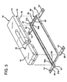
- a bushing block mounting system includes a bushing block 10 and a bushing block mounting frame 20 positioning the bushing block 10 between a forehearth section 2 of a conventional direct-heat glass-melting furnace and a conventional attenuating bushing 9.
- the bushing block 10 inciudes an elongated orifice 12 to permit flow-through communication between the forehearth section 2 and the bushing 9.
- the orifice 12 may be any size, shape or geometry which delivers molten glass from the forehearth 2 to the bushing 9 at a predetermined rate.
- the bushing 9 is of a conventional configuration, and includes one or more orifices 9c, which receive molten glass from the bushing block 10 and thereby form one or more attenuated glass fibers of molten glass exiting the bushing 9 theretbrough.
- the bushing block 10 preferably is constructed from any suitable refractory material, such as zircon, and includes a generally rectangular shape having a shoulder 14 which continues substantially around the periphery of the bushing block 10, thereby defining an upper portion 11 of the bushing block 10 residing above the shoulder 14 and a lower portion 13 of the bushing block 10 residing below the shoulder 14.
- the upper portion 11 of the bushing block 10 includes an upper mating surface 15 which sealingly abuts a mating surface 2' of the forehearth section 2 of the furnace to provide sealed flow-through communication of molten glass from the forehearth 2, through the orifice 12 of the bushing block 10 and into the bushing 9.
- the frame 20 preferably is constructed from stainless steel, or any other high-temperature alloy known to those skilled in the art, and is of a generally rectangular shape defining a generally rectangular opening 23 for at least partially receiving the block 10 therein.
- Frame 20 includes a peripheral upstanding side wall 22 and a peripheral ledge 24 projecting inwardly therefrom.
- the side wall 22 and peripheral ledge 24 are also referred to herein as a structure.
- First and second rear-end arms 26, 26', respectively, project sway from a rear end of the frame 20 and are spaced vertically below the ledge 24 by the upstanding wall 22.
- Arms 25, 25', 26, 26' cooperate to mount the frame 20 to the forehearth section 2 of the furnace, such as, by bolts "B" through slots "S”.
- a conventional bushing frame 3 is used to sealingly position the bushing 9 against the bushing block 10 and includes a first lip 3' upon which arms 9' of the bushing 9 rest.
- One or more threaded positioning rods 7 are secured to the frame 20, such as by threaded holes 24a in the ledge 24, and depend dowawardly therefrom to permit the bushing frame 3 to be positioned relative to the bushing block frame 20.
- rods 7 may be fixedly secured to the bushing block frame 20, such as, by welding.
- First and second tabs 27, 27' project outwardly from the frame 20, along a lengthwise direction thereof, each having a threaded hole 27a spared along the lengthwise direction of the frame 20 from the holes 24a by a short distanec, such as, for example 1 inch.
- the tabs 27, 27' are preferably coplanar with the ledge 24 of the frame 20.
- the bushing frame 3 is mounted to the support plate 6 of the forehearth 2 by one or more support lugs 3a (see, Fig. 4), which engage a second lip 3" of the bushing frame 3 and clamp the bushing frame 3 against the forehearth 2, such as by bolts "B 1 ".
- Arms 25, 25', 26, 26' are shown as being substantially planar; however, arms 25, 25', 26, 26' may have non-planar portions (not shown) for mounting the frame 20 to the forehearth 2 around portions of the forehearth 2, for example, the bushing frame 3. Moreover, lower portion 13 of block 10 depends from the opening 23 a sufficient distance to permit the lower scaling surface 15' of the block 10 to sealingly abut the sealing surface 9" of the bushing 9.
- Support bars 4, 5 (Fig. 2) of the prior art are not required to mount the block 10 to the foreheacth 2 because the block 10 is supported substantially around its entire periphery by the frame 20. Moreover, because the block 10 is supported at the shoulder 14, which is vertically spaced above the lower sealing surface 15' of the block 10, substantially all of the lower sealing surface 15' of the block 15 is exposed to the bushing 9 and to the bushing frame 3, thereby permitting a bushing frame 3 with a length L 3 which is less than the length L 13 of the upper portion 11 of the block 10 and which is substantially the same as the length L 11 of the lower portion 13 of the block 10 to be positioned therebelow.
- a bushing 9 having a length which is greater than the length L 11 of the block 10 may be positioned therebelow, so long as a main body portion of the bushing 9 is able to seal against the bushing block 10.
- positioning rods 7 may be secured to tab holes 27a, rather than to holes 24a, thereby permitting a longer bushing frame 3 supporting a longer bushing 9 to be positioned between the threaded rods 7, while still being sealingly positioned against the bushing block 10, such that the length L 3 of the bushing frame 3 (and of the bushing 9 supported therein) is greater than the lengths L 13 , L 11 of the block 10.
- improved, longer bushings may be affixed to the forehearth sections of older furnaces, which, heretofore, was not permitted due to the size limitations of the support bars 4, 5 (Fig. 2).
- the block 10 is supported by the frame 20 substantially around its periphery, fracture of the block 10, while seated within the flame 20, will not cause the block 10 to fall out of the frame 20. The threat of catastrophic machine failure, then, is substantially eliminated.
- the block 10 may be constructed of an experimental malarial which, in the prior art, may not have been attempted for fear of fracture resulting in the catasuophic machine failure.
- the flame 20 of the present invention safeguards against machine failure by continuing to support the block 10 therein, even after fracture of the block 10, for example, as a result of thermal shock.
- the frame 20 securely retains the bushing block 10 and provides sufficient clamping force to create a sealing fit between the upper surface of the bushing block 10 and the sealing surface of the forehearth 2, but does not create excessive or unnecessary compressive forces within the block 10.
- a bushing block mounting system includes many components in common with the bushing block system of the preferred embodiment hereof and like reference numerals are intended to represent like components.
- the bushing block mounting system according to the present embodiment includes a mounting flame 120 defining an opening 123 and having a peripheral upstanding side wall 122 and a peripheral ledge 124 projecting inwardly therefrom.
- the ledge 24 (Fig. 4) is spaced vertically above arms 25, 25', 26, 26' (Fig. 4)
- the ledge 124 of the frame 120 of the present embodiment is substantially coplanar with arms (only arm 125 being shown in Fig.
- a block 110 having a shoulder 114 is at least partially received in the opening 123 as described above such that a lower portion 113 of the block 110 is suspended by the shoulder 114 and such that an upper portion 111 of the block 110 is seated within the frame 120.
- the block 110 is positioned between the forehearth 2 and the bushing 9 (Fig. 4) such that an upper sealing surface 115 of the block 110 sealingly abuts a sealing surface 2' of the forehearth and 8 lower sealing surface 115' of the block 110 sealingly abuts a sealing surface of the bushing 9 as described above.
Landscapes
- Engineering & Computer Science (AREA)
- Chemical & Material Sciences (AREA)
- General Life Sciences & Earth Sciences (AREA)
- Geochemistry & Mineralogy (AREA)
- Manufacturing & Machinery (AREA)
- Materials Engineering (AREA)
- Organic Chemistry (AREA)
- Life Sciences & Earth Sciences (AREA)
- Furnace Housings, Linings, Walls, And Ceilings (AREA)
- Insulators (AREA)
- Furnace Details (AREA)
- Carbon Steel Or Casting Steel Manufacturing (AREA)
- Furnace Charging Or Discharging (AREA)
- Studio Circuits (AREA)
- Perforating, Stamping-Out Or Severing By Means Other Than Cutting (AREA)
- Surgical Instruments (AREA)
- Compressor (AREA)
Abstract
Description
Claims (5)
- A bushing block assembly (10) adapted to be positioned between a forehearth (2) and a bushing (9), the bushing block assembly comprising:a bushing block (11) having an orifice (12) providing flow-through communication between the forehearth and the bushing and a downwardly facing shoulder (14) extending around the periphery thereof; anda bushing block mounting frame (20) having an inwardly projecting ledge (24) defining an opening (23) for receiving the bushing block (10) and for supporting the shoulder (14) substantially completely around the periphery of the bushing block.
- A bushing block assembly according to claim 1, wherein the mounting frame (20) further includes an upstanding portion (22) around the outer periphery of the ledge (24) defining a seat for receiving the bushing block (10).
- A bushing block assembly according to claim 1 or claim 2, wherein the shoulder (14) defines upper (11) and lower (13) portions of the bushing block (10), the lower portion (13) being received by the opening (23) in the mounting frame (20) and the upper portion (11) being seated within the seat.
- A bushing block assembly according to any one of claims 1 to 3, wherein the mounting frame (20) includes outwardly projecting arms (25,25',26,26') by means of which the assembly can be mounted to the forehearth (2).
- A bushing system adapted to be coupled to a forehearth (2), comprising:a bushing block assembly according to any one of claims 1 to 4; anda bushing assembly including a bushing (9) and a bushing support frame (3), adapted to be coupled to one of the bushing block mounting frame (20) and the forehearth (2), and wherein the bushing has a length which is substantially equal to or greater than that of the bushing block (10).
Applications Claiming Priority (3)
| Application Number | Priority Date | Filing Date | Title |
|---|---|---|---|
| US36485099A | 1999-07-30 | 1999-07-30 | |
| US364850 | 1999-07-30 | ||
| PCT/US2000/020208 WO2001009050A1 (en) | 1999-07-30 | 2000-07-25 | Bushing block mounting frame |
Publications (2)
| Publication Number | Publication Date |
|---|---|
| EP1202939A1 EP1202939A1 (en) | 2002-05-08 |
| EP1202939B1 true EP1202939B1 (en) | 2003-05-21 |
Family
ID=23436364
Family Applications (1)
| Application Number | Title | Priority Date | Filing Date |
|---|---|---|---|
| EP00948945A Expired - Lifetime EP1202939B1 (en) | 1999-07-30 | 2000-07-25 | Bushing block mounting frame |
Country Status (12)
| Country | Link |
|---|---|
| EP (1) | EP1202939B1 (en) |
| KR (1) | KR100686499B1 (en) |
| AT (1) | ATE240911T1 (en) |
| AU (1) | AU6236600A (en) |
| BR (1) | BR0012867B1 (en) |
| CA (1) | CA2380080C (en) |
| DE (1) | DE60002889T2 (en) |
| ES (1) | ES2198330T3 (en) |
| MX (1) | MXPA02000891A (en) |
| NO (1) | NO20020468L (en) |
| WO (1) | WO2001009050A1 (en) |
| ZA (1) | ZA200200788B (en) |
Family Cites Families (1)
| Publication number | Priority date | Publication date | Assignee | Title |
|---|---|---|---|---|
| US4704150A (en) * | 1986-12-05 | 1987-11-03 | Ppg Industries, Inc. | Glass fiber forming bushing assembly |
-
2000
- 2000-07-25 KR KR1020027001290A patent/KR100686499B1/en not_active Expired - Fee Related
- 2000-07-25 AU AU62366/00A patent/AU6236600A/en not_active Abandoned
- 2000-07-25 EP EP00948945A patent/EP1202939B1/en not_active Expired - Lifetime
- 2000-07-25 CA CA002380080A patent/CA2380080C/en not_active Expired - Fee Related
- 2000-07-25 AT AT00948945T patent/ATE240911T1/en not_active IP Right Cessation
- 2000-07-25 MX MXPA02000891A patent/MXPA02000891A/en active IP Right Grant
- 2000-07-25 ES ES00948945T patent/ES2198330T3/en not_active Expired - Lifetime
- 2000-07-25 DE DE60002889T patent/DE60002889T2/en not_active Expired - Lifetime
- 2000-07-25 WO PCT/US2000/020208 patent/WO2001009050A1/en not_active Ceased
- 2000-07-25 BR BRPI0012867-8A patent/BR0012867B1/en not_active IP Right Cessation
-
2002
- 2002-01-29 ZA ZA200200788A patent/ZA200200788B/en unknown
- 2002-01-29 NO NO20020468A patent/NO20020468L/en not_active Application Discontinuation
Also Published As
| Publication number | Publication date |
|---|---|
| ES2198330T3 (en) | 2004-02-01 |
| DE60002889D1 (en) | 2003-06-26 |
| CA2380080A1 (en) | 2001-02-08 |
| NO20020468D0 (en) | 2002-01-29 |
| ATE240911T1 (en) | 2003-06-15 |
| BR0012867B1 (en) | 2009-01-13 |
| WO2001009050A1 (en) | 2001-02-08 |
| KR20020029674A (en) | 2002-04-19 |
| NO20020468L (en) | 2002-03-21 |
| AU6236600A (en) | 2001-02-19 |
| CA2380080C (en) | 2009-06-02 |
| DE60002889T2 (en) | 2004-05-13 |
| BR0012867A (en) | 2002-04-16 |
| MXPA02000891A (en) | 2002-08-06 |
| ZA200200788B (en) | 2003-03-26 |
| EP1202939A1 (en) | 2002-05-08 |
| KR100686499B1 (en) | 2007-02-23 |
Similar Documents
| Publication | Publication Date | Title |
|---|---|---|
| US6196029B1 (en) | Low profile bushing for making fibers | |
| JP3720387B2 (en) | Apparatus and method for melting glass | |
| US3859070A (en) | Laminar refractory structures for forming glass fibers | |
| US5879427A (en) | Bushing assemblies for fiber forming | |
| CA1273206A (en) | Bushing construction | |
| US4704150A (en) | Glass fiber forming bushing assembly | |
| US4536202A (en) | Drain bushing | |
| EP1202939A1 (en) | Bushing block mounting frame | |
| RU2466825C2 (en) | Teeming nozzle for continuous casting | |
| EP1832559A1 (en) | Adjustable positioning apparatus for cooling members and method | |
| EP1509478B1 (en) | Fiber forming bushing assembly having flange support | |
| JPH0248501B2 (en) | ||
| JP2778948B2 (en) | Sliding gate valve assembly | |
| CZ292248B6 (en) | Composite and monolithic refractory structure and process for producing thereof | |
| US5948135A (en) | Bushing insulation and frame arrangement for making fiber glass | |
| US4591371A (en) | Glass fiber forming bushing construction | |
| CA1227617A (en) | Method and an apparatus for manufacturing a hollow steel ingot | |
| KR200226269Y1 (en) | Electrode assembling device for use in molten metal purifying vessel | |
| CN111910031A (en) | Hanging adjusting device for tapping machine of blast furnace and using method | |
| CN217127597U (en) | Crucible mold and protective device thereof | |
| JP2984173B2 (en) | Ladle refining electrode device | |
| US20110240248A1 (en) | Casting nozzle for continuous casting | |
| US5350008A (en) | Mold assembly for thermo-mold continuous casting | |
| US4738701A (en) | Method and apparatus for forming glass fibers | |
| KR100726416B1 (en) | Furnace chiller |
Legal Events
| Date | Code | Title | Description |
|---|---|---|---|
| PUAI | Public reference made under article 153(3) epc to a published international application that has entered the european phase |
Free format text: ORIGINAL CODE: 0009012 |
|
| 17P | Request for examination filed |
Effective date: 20020213 |
|
| AK | Designated contracting states |
Kind code of ref document: A1 Designated state(s): AT BE CH CY DE DK ES FI FR GB GR IE IT LI LU MC NL |
|
| AX | Request for extension of the european patent |
Free format text: AL;LT;LV;MK;RO;SI |
|
| 17Q | First examination report despatched |
Effective date: 20020607 |
|
| GRAH | Despatch of communication of intention to grant a patent |
Free format text: ORIGINAL CODE: EPIDOS IGRA |
|
| RBV | Designated contracting states (corrected) |
Designated state(s): AT BE CH CY DE DK ES FI FR GB GR IE IT LI LU MC NL PT SE |
|
| GRAH | Despatch of communication of intention to grant a patent |
Free format text: ORIGINAL CODE: EPIDOS IGRA |
|
| GRAA | (expected) grant |
Free format text: ORIGINAL CODE: 0009210 |
|
| AK | Designated contracting states |
Designated state(s): AT BE CH CY DE DK ES FI FR GB GR IE IT LI LU MC NL PT SE |
|
| PG25 | Lapsed in a contracting state [announced via postgrant information from national office to epo] |
Ref country code: CH Free format text: LAPSE BECAUSE OF FAILURE TO SUBMIT A TRANSLATION OF THE DESCRIPTION OR TO PAY THE FEE WITHIN THE PRESCRIBED TIME-LIMIT Effective date: 20030521 Ref country code: FI Free format text: LAPSE BECAUSE OF FAILURE TO SUBMIT A TRANSLATION OF THE DESCRIPTION OR TO PAY THE FEE WITHIN THE PRESCRIBED TIME-LIMIT Effective date: 20030521 Ref country code: LI Free format text: LAPSE BECAUSE OF FAILURE TO SUBMIT A TRANSLATION OF THE DESCRIPTION OR TO PAY THE FEE WITHIN THE PRESCRIBED TIME-LIMIT Effective date: 20030521 Ref country code: AT Free format text: LAPSE BECAUSE OF FAILURE TO SUBMIT A TRANSLATION OF THE DESCRIPTION OR TO PAY THE FEE WITHIN THE PRESCRIBED TIME-LIMIT Effective date: 20030521 |
|
| REG | Reference to a national code |
Ref country code: GB Ref legal event code: FG4D |
|
| REG | Reference to a national code |
Ref country code: CH Ref legal event code: EP |
|
| REG | Reference to a national code |
Ref country code: IE Ref legal event code: FG4D |
|
| REF | Corresponds to: |
Ref document number: 60002889 Country of ref document: DE Date of ref document: 20030626 Kind code of ref document: P |
|
| PG25 | Lapsed in a contracting state [announced via postgrant information from national office to epo] |
Ref country code: IE Free format text: LAPSE BECAUSE OF NON-PAYMENT OF DUE FEES Effective date: 20030725 Ref country code: LU Free format text: LAPSE BECAUSE OF NON-PAYMENT OF DUE FEES Effective date: 20030725 Ref country code: CY Free format text: LAPSE BECAUSE OF FAILURE TO SUBMIT A TRANSLATION OF THE DESCRIPTION OR TO PAY THE FEE WITHIN THE PRESCRIBED TIME-LIMIT Effective date: 20030725 |
|
| PG25 | Lapsed in a contracting state [announced via postgrant information from national office to epo] |
Ref country code: MC Free format text: LAPSE BECAUSE OF NON-PAYMENT OF DUE FEES Effective date: 20030731 |
|
| PG25 | Lapsed in a contracting state [announced via postgrant information from national office to epo] |
Ref country code: GR Free format text: LAPSE BECAUSE OF FAILURE TO SUBMIT A TRANSLATION OF THE DESCRIPTION OR TO PAY THE FEE WITHIN THE PRESCRIBED TIME-LIMIT Effective date: 20030821 Ref country code: SE Free format text: LAPSE BECAUSE OF FAILURE TO SUBMIT A TRANSLATION OF THE DESCRIPTION OR TO PAY THE FEE WITHIN THE PRESCRIBED TIME-LIMIT Effective date: 20030821 Ref country code: DK Free format text: LAPSE BECAUSE OF FAILURE TO SUBMIT A TRANSLATION OF THE DESCRIPTION OR TO PAY THE FEE WITHIN THE PRESCRIBED TIME-LIMIT Effective date: 20030821 |
|
| PG25 | Lapsed in a contracting state [announced via postgrant information from national office to epo] |
Ref country code: PT Free format text: LAPSE BECAUSE OF FAILURE TO SUBMIT A TRANSLATION OF THE DESCRIPTION OR TO PAY THE FEE WITHIN THE PRESCRIBED TIME-LIMIT Effective date: 20030911 |
|
| LTIE | Lt: invalidation of european patent or patent extension |
Effective date: 20030521 |
|
| REG | Reference to a national code |
Ref country code: CH Ref legal event code: PL |
|
| REG | Reference to a national code |
Ref country code: ES Ref legal event code: FG2A Ref document number: 2198330 Country of ref document: ES Kind code of ref document: T3 |
|
| ET | Fr: translation filed | ||
| PLBE | No opposition filed within time limit |
Free format text: ORIGINAL CODE: 0009261 |
|
| STAA | Information on the status of an ep patent application or granted ep patent |
Free format text: STATUS: NO OPPOSITION FILED WITHIN TIME LIMIT |
|
| REG | Reference to a national code |
Ref country code: IE Ref legal event code: MM4A |
|
| 26N | No opposition filed |
Effective date: 20040224 |
|
| PGFP | Annual fee paid to national office [announced via postgrant information from national office to epo] |
Ref country code: FR Payment date: 20110805 Year of fee payment: 12 |
|
| PGFP | Annual fee paid to national office [announced via postgrant information from national office to epo] |
Ref country code: ES Payment date: 20110726 Year of fee payment: 12 Ref country code: DE Payment date: 20110727 Year of fee payment: 12 Ref country code: GB Payment date: 20110725 Year of fee payment: 12 |
|
| PGFP | Annual fee paid to national office [announced via postgrant information from national office to epo] |
Ref country code: BE Payment date: 20110728 Year of fee payment: 12 Ref country code: IT Payment date: 20110726 Year of fee payment: 12 Ref country code: NL Payment date: 20110728 Year of fee payment: 12 |
|
| BERE | Be: lapsed |
Owner name: *OWENS CORNING Effective date: 20120731 |
|
| REG | Reference to a national code |
Ref country code: NL Ref legal event code: V1 Effective date: 20130201 |
|
| GBPC | Gb: european patent ceased through non-payment of renewal fee |
Effective date: 20120725 |
|
| REG | Reference to a national code |
Ref country code: FR Ref legal event code: ST Effective date: 20130329 |
|
| PG25 | Lapsed in a contracting state [announced via postgrant information from national office to epo] |
Ref country code: NL Free format text: LAPSE BECAUSE OF NON-PAYMENT OF DUE FEES Effective date: 20130201 Ref country code: FR Free format text: LAPSE BECAUSE OF NON-PAYMENT OF DUE FEES Effective date: 20120731 Ref country code: GB Free format text: LAPSE BECAUSE OF NON-PAYMENT OF DUE FEES Effective date: 20120725 Ref country code: DE Free format text: LAPSE BECAUSE OF NON-PAYMENT OF DUE FEES Effective date: 20130201 |
|
| REG | Reference to a national code |
Ref country code: DE Ref legal event code: R119 Ref document number: 60002889 Country of ref document: DE Effective date: 20130201 |
|
| PG25 | Lapsed in a contracting state [announced via postgrant information from national office to epo] |
Ref country code: BE Free format text: LAPSE BECAUSE OF NON-PAYMENT OF DUE FEES Effective date: 20120731 Ref country code: IT Free format text: LAPSE BECAUSE OF NON-PAYMENT OF DUE FEES Effective date: 20120725 |
|
| PG25 | Lapsed in a contracting state [announced via postgrant information from national office to epo] |
Ref country code: ES Free format text: LAPSE BECAUSE OF NON-PAYMENT OF DUE FEES Effective date: 20120726 |
|
| REG | Reference to a national code |
Ref country code: ES Ref legal event code: FD2A Effective date: 20131031 |