EP1202590A2 - Mobile radio terminal and its moving speed detecting method - Google Patents
Mobile radio terminal and its moving speed detecting method Download PDFInfo
- Publication number
- EP1202590A2 EP1202590A2 EP01125414A EP01125414A EP1202590A2 EP 1202590 A2 EP1202590 A2 EP 1202590A2 EP 01125414 A EP01125414 A EP 01125414A EP 01125414 A EP01125414 A EP 01125414A EP 1202590 A2 EP1202590 A2 EP 1202590A2
- Authority
- EP
- European Patent Office
- Prior art keywords
- prediction
- pilot signal
- mobile radio
- radio terminal
- moving speed
- Prior art date
- Legal status (The legal status is an assumption and is not a legal conclusion. Google has not performed a legal analysis and makes no representation as to the accuracy of the status listed.)
- Withdrawn
Links
Images


Classifications
-
- H—ELECTRICITY
- H04—ELECTRIC COMMUNICATION TECHNIQUE
- H04W—WIRELESS COMMUNICATION NETWORKS
- H04W64/00—Locating users or terminals or network equipment for network management purposes, e.g. mobility management
-
- G—PHYSICS
- G01—MEASURING; TESTING
- G01S—RADIO DIRECTION-FINDING; RADIO NAVIGATION; DETERMINING DISTANCE OR VELOCITY BY USE OF RADIO WAVES; LOCATING OR PRESENCE-DETECTING BY USE OF THE REFLECTION OR RERADIATION OF RADIO WAVES; ANALOGOUS ARRANGEMENTS USING OTHER WAVES
- G01S11/00—Systems for determining distance or velocity not using reflection or reradiation
- G01S11/02—Systems for determining distance or velocity not using reflection or reradiation using radio waves
Definitions
- the present invention relates to a mobile radio terminal and its moving speed detecting method.
- a method to detect a moving speed of a mobile radio terminal the methods such as (1) a method to estimate a speed by detecting a pitch of fading, (2) a method to estimate a speed from a time difference between a transmission frame and a reception frame, (3) a method to estimate a speed from a movement on a time axis by detecting a Path in a CDMA system and (4) a method to estimate a speed from the displacement of a career frequency by detecting a Path in a CDMA system have been already known.
- the present invention has been made taking the problems into consideration, an object of which is to provide a mobile radio terminal capable of detecting a moving speed of the mobile radio terminal with a time and a moving distance which are shorter compared to a conventional method and its moving speed detecting method.
- the present invention provides a moving speed detecting method of a mobile radio terminal which makes communication with a base station broadcasting a pilot signal, comprising the steps of:
- the present invention provides a moving speed detecting method of a mobile radio terminal which makes communication with a base station broadcasting a pilot signal, comprising the steps of:
- the present invention provides a mobile radio terminal which makes communication with a base station broadcasting a pilot signal, comprising:
- the present invention provides mobile radio terminal which makes communication with a base station broadcasting a pilot signal, comprising:
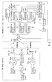
- FIG. 1 shows a constitution of the first embodiment according to the present invention.
- a left side of FIG. 1 comprises a base station 100 and a right side thereof comprises a mobile radio terminal 200.
- the base station 100 includes a pair of transmission/ reception antennas 101a and 101b, a radio reception circuit 112, radio reception circuits 102a and 102b, counting circuits 103a and 103b, a switch 104 and a decoder 113.
- the mobile radio terminal 200 includes an antenna 1, a radio reception circuit 2, despreading circuits 3a, 3b and 3c, prediction circuits 4a1, 4a2, 4b1 and 4b2, a prediction error comparing circuit 5, selection circuits 6a and 6b, an encoder 7 and a radio transmission circuit 8.
- the output of the prediction circuits 4a1 and 4a2 is only connected to the prediction error comparing circuit 5.
- an IMT-2000 mobile communication system defined by 3GPP is taken as an example for a parameter with regard to transmission.
- a radio frequency is 2 GHz band
- a time interval to control a transmission antenna is about 667 ⁇ seconds equivalent to 1.5 KHz
- the number of antennas of the base station and the number of pilot signals which are peculiar to the antenna is 2.
- the pilot signals are orthogonal each other in code.
- a unique pilot signal is steadily broadcast from two transmission/reception antennas 101a and 101b of the base station 100.
- the information broadcast from the base station 100 to the mobile radio terminal 200 is spreaded by means which is not illustrated in the drawings so as to be transmitted from any one of two transmission/reception antennas 101a and 101b. It is decided depending on the information from the mobile radio terminal 200 from which antenna the information is transmitted.
- the IMT-2000 system controls the weight of a signal (a quantity of the information) to be transmitted from each of the two transmission/ reception antennas 101a and 101b including a phase.
- the IMT-2000 system comprises such a system as to determine a transmission antenna alternatively (the weight of the antenna is 0 or 1 complementarily).
- Each of the two transmission/reception antennas 101a and 101b transmits a signal including an at least specific pilot signal.
- the signals from the two transmission/reception antennas 101a and 101b reach to the antenna 1 of the mobile radio terminal 200 via separate transmission paths.
- Each of transmission paths includes scattering by the object around the mobile radio terminal 200, so that so called rayleigh fading is generated in accordance with the movement of the mobile radio terminal 200.
- the mobile radio terminal 200 is capable of separately detecting amplitude and a phase of two pilot signals by two despreading circuits 3a and 3b.
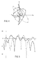
- FIG. 4 shows tracks of separate pilot signals on a complex plane by a solid line and a broken line.
- FIG. 5 shows an amplitude variation of the same fading by dB indication.
- the mobile radio terminal 200 observes the transmission loss from the two base station antennas 101a and 101b as described above. Then, as a result, it is detected from which antenna the information component should be transmitted to receive the information component at a higher level.
- This detection result is encoded by an encoder 7 as a transmission antenna selection command and then, the encoded result is transmitted via a transmitter 8 and the antenna 1.
- the base station 100 receives the transmitted result by a receiver 112 via the antennas 101a and 101b and a decoder 113 extracts a transmission antenna selection command from the received result so as to control a transmission antenna changing switch 104.
- a principle of a feed back type transmission diversity is as described above.
- the mobile radio terminal 200 observes the transmission loss of the two transmission paths and the transmission antenna selection command is transmitted in units of a slot (1,500 Hz, 667 ⁇ seconds).
- the base station 100 receives the transmission antenna selection command and switches one of antenna to another antenna to transmit the information component in accordance with this command also in units of a slot.
- the mobile radio terminal 200 predicts the transmission loss in the (N + 2)th slot on the basis of the observation in the (N)th slot, so that the mobile radio terminal 200 generates the transmission antenna selection command.
- a method to predict the transmission loss As a method to predict the transmission loss, a method has been conventionally known such that an observation value in the (N)th slot is defined as a prediction characteristic value of the transmission loss in the (N+2)th slot (a prediction method 1). This method is effective when the moving speed of the mobile radio terminal 200 is low. However, as the moving speed becomes higher, the prediction accuracy is deteriorated, so that the prediction errors are increased. If the prediction error according to the prediction method 1 is obtained by a simulation in the case that a radio frequency and a slot period or the like are defined as a parameter of IMT-2000 of 3GPP, a property shown in FIG. 6 by a narrow line is obtained. As obvious from the drawing, the prediction error is not so large, i.e., -12 dB at 2m per second. However, the prediction error is deteriorated at 18m per second, i.e., -6 dB.
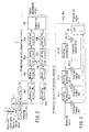
- a method is suggested such that it predicts the transmission loss by the prediction circuit configured by a FIR filter of a high order more than 30 stages as shown in FIG. 3.
- reference numerals 41-1, 41-2, 41-3, ⁇ , and 41-72 denote holding circuits (1) to (72) for holding the inputted measured values.
- reference numerals 42-1, 42-2, 42-3, ⁇ and 42-73 denote multiplication circuits to multiply the measured value by a constant number.
- a counting circuit 43 adds the output from the above described multiplication circuits 42-1, 42-4, 42-3, ⁇ and 42-73 and outputs the sum as the prediction value.
- FIG. 3 shows an example of a FIR filter having 73 stages. If the prediction error is obtained by a simulation in the case of using 73 pieces of the coefficients shown in FIG. 7 corresponding to this, a property shown by a bold line shown in FIG. 6 is obtained. As obvious from the drawing, the prediction error in the range of 2m per second to 18m per second is constantly about -9 dB.
- the prediction error is compared to the observation value after time passes from the prediction, it is possible to know how that prediction is precise. Alternatively, comparing respective prediction errors of the above described two prediction methods in which relations between the moving speed and the prediction errors are different, it is possible to predict the moving speed of the mobile radio terminal 200.
- FIG. 2 shows a specific constitution to estimate the moving speed of the mobile radio terminal 200.
- the prediction error comparing circuit 5 is configured by delay circuits 51a and 51b, error generation circuits 52a and 52b, averaging circuits 53a and 53b and a comparing table 54.
- a reference numeral 1 denotes an antenna
- a reference numeral 2 denotes a radio reception circuit
- a reference numeral 3a denotes a despreading circuit
- a reference numeral 50 denotes a sampling circuit.
- the prediction characteristic value in the (N+2)th slot which is obtained by each the two prediction methods at the (N)th slot is delayed for two slots by the delay circuits 51a and 51b. Then, the delayed prediction value is compared to the observation value which is obtained at the (N+2)th slot in the error generation circuits 52a and 52b, so that the prediction error is generated.
- the prediction errors predicted by respective prediction methods are compared to each other by the comparing table 54 after removing the influences such as a noise or the like therefrom by the averaging circuits 53a and 53b.
- the comparing table 54 stores the data such that it outputs the estimation speed 2m per second if the error predicted by the prediction method 1 is -12 dB and the error predicted by the prediction method 2 is -9 dB and it outputs the estimation speed 18m per second if the error predicted by the prediction method 1 is -6 dB and the error predicted by the prediction method 2 is -9 dB.
- the methods to estimate the moving speed of the mobile radio terminal 200 are as described above.
- the predicted errors are compared with respect to only one pilot signal.
- comparing the predicted errors with respect to other pilot signal it is possible to improve the accuracy in the estimation of the speed with putting together the results.
- a parameter such as the number of the FIR stages in the prediction method 2 shown in the above described first embodiment and the coefficients shown in FIG. 7 are taken as only an example. If the number of the FIR stages is defined not less than about 30 stages, it is possible to obtain an effect by carrying out the present invention.
- the IMT-2000 system of 3GPP is taken as an example.
- CDMA code division multiple access
- AMPS analog modulation system
- most of the mobile radio communication systems, which employ a digital communication system include a signal referred to as a pilot signal and a unique word, so that, if the present invention is performed with respect to this signal, as shown in the above described embodiment, the fading is predicted by the different prediction methods and it is possible that the mobile speed is estimated from these prediction accuracy.
- a content of the comparing table 54 which is employed in the above described embodiment, is changed by an electric power ratio of a desired signal and a noise (C/N). Therefore, it is possible to improve the accuracy of the estimation of the speed by modifying the comparing table and using a table to also input the C/N ratio.
- the present invention it is possible to estimate the moving speed of the mobile radio terminal by a short measurement distance, during a short measurement time and further, with a higher degree of accuracy.
Landscapes
- Engineering & Computer Science (AREA)
- Computer Networks & Wireless Communication (AREA)
- Signal Processing (AREA)
- Physics & Mathematics (AREA)
- General Physics & Mathematics (AREA)
- Radar, Positioning & Navigation (AREA)
- Remote Sensing (AREA)
- Mobile Radio Communication Systems (AREA)
- Radio Transmission System (AREA)
Abstract
Description
Claims (15)
- A moving speed detecting method of a mobile radio terminal (200) which makes communication with a base station (100) broadcasting a pilot signal, characterized by comprising the steps of:receiving the pilot signal at a first time;predicting a first prediction characteristic value of a signal to be received at a second time based on the received pilot signal by using a first prediction method;predicting a second prediction characteristic value of a signal to be received at the second time based on the received pilot signal by using a second prediction method;receiving a pilot signal at the second time after receiving the pilot signal at the first time;generating an actual value of the pilot signal received at the second time;calculating a first difference by comparing the predicted first prediction characteristic value with the generated actual value;calculating a second difference by comparing the predicted second prediction characteristic value with the generated actual value;detecting moving speed of the mobile radio terminal apparatus based on the calculated first and second differences.
- A moving speed detecting method of a mobile radio terminal according to claim 1,
characterized in that each of the steps of predicting the first and second prediction characteristic values includes a step of predicting a phase and an amplitude of the pilot signal, and the information with regard to the phase and the amplitude of the pilot signal is commonly used as feed back information of a feedback type transmission diversity. - A moving speed detecting method of a mobile radio terminal according to claim 1,
characterized in that one of said plurality of prediction methods comprises a method such that a sampled pilot signal is defined as a prediction value of a next pilot signal as it is. - A moving speed detecting method of a mobile radio terminal according to claim 1,
characterized in that a CN ratio of the observed pilot signal is used as a parameter in the steps of calculating the first and second differences. - A moving speed detecting method of a mobile radio terminal (200) which makes communication with a base station (100) broadcasting a pilot signal, characterized by comprising the steps of:predicting phases and amplitudes of the pilot signal from the base station (100) by using a plurality of prediction methods having different characteristics;calculating errors for the prediction results, which are obtained for respective prediction methods in said prediction step; andcomparing the prediction errors with respect to each of the prediction methods, which are calculated by said calculating step, to detect a moving speed of said mobile radio terminal (200).
- A moving speed detecting method of a mobile radio terminal according to claim 1,
characterized in that the information with regard to the phase and the amplitude of the pilot signal, which are predicted by said prediction step, is commonly used as feed back information of a feedback type transmission diversity. - A moving speed detecting method of a mobile radio terminal according to claim 1,
characterized in that one of said plurality of prediction methods comprises a method such that a sampled pilot signal is defined as a prediction value of a next pilot signal as it is. - A mobile radio terminal (200) which makes communication with a base station (100) broadcasting a pilot signal, characterized by comprising:first receiving means for receiving the pilot signal at a first time;predicting means (4a1, 4b2) for predicting a first prediction characteristic value of a signal to be received at a second time based on the received pilot signal by using a first prediction method, and for predicting a second prediction characteristic value of a signal to be received at the second time based on the received pilot signal by using a second prediction method;second receiving means for receiving a pilot signal at the second time after receiving the pilot signal at the first time;generating means for generating an actual value of the pilot signal received at the second time;calculating means for calculating a first difference by comparing the predicted first prediction characteristic value with the generated actual value and for calculating a second difference by comparing the predicted second prediction characteristic value with the generated actual value;detecting means (5) for detecting moving speed of the mobile radio terminal apparatus based on the calculated first and second differences.
- A mobile radio terminal according to claim 8, characterized in that the predicting means includes means for predicting a phase and an amplitude of the pilot signal, wherein the information with regard to the phase and the amplitude of the pilot signal, which are predicted by said predicting unit, is commonly used as the feed back information of a feedback type transmission diversity.
- A mobile radio terminal according to claim 8,
characterized in that one of said plurality of prediction methods comprises a method such that a sampled pilot signal is defined as a prediction value of a next pilot signal as it is. - A mobile radio terminal according to claim 8,
characterized in that a CN ratio of the observed pilot signal is used as a parameter in calculating the first and second differences by said calculating means. - A mobile radio terminal (200) which makes communication with a base station (100) broadcasting a pilot signal, characterized by comprising:a predicting unit (4a1, 4b2) to predict phases and amplitudes of the pilot signal from the base station by using a plurality of prediction methods having different characteristics;a calculating unit to calculate errors for the prediction results which are obtained for respective prediction methods by said predicting unit (4a1, 4b2); anda prediction error comparing unit (5) to compare the prediction errors with respect to each of the prediction methods, which are calculated by said calculating unit, to detect a moving speed of said mobile radio terminal (200).
- A mobile radio terminal according to claim 12, characterized in that the information with regard to the phase and the amplitude of the pilot signal, which are predicted by said predicting unit (4a1, 4b2), is commonly used as the feed back information of a feedback type transmission diversity.
- A mobile radio terminal according to claim 12, characterized in that one of said plurality of prediction methods comprises a method such that a sampled pilot signal is defined as a prediction value of a next pilot signal as it is.
- A mobile radio terminal according to claim 12,
characterized in that a CN ratio of the observed pilot signal is used as a parameter upon comparing the prediction error in a plurality of prediction methods having different characteristics in said prediction error comparing unit (5).
Applications Claiming Priority (2)
| Application Number | Priority Date | Filing Date | Title |
|---|---|---|---|
| JP2000333969A JP2002141858A (en) | 2000-10-31 | 2000-10-31 | Mobile radio terminal and moving speed detecting method thereof |
| JP2000333969 | 2000-10-31 |
Publications (2)
| Publication Number | Publication Date |
|---|---|
| EP1202590A2 true EP1202590A2 (en) | 2002-05-02 |
| EP1202590A3 EP1202590A3 (en) | 2003-05-14 |
Family
ID=18809965
Family Applications (1)
| Application Number | Title | Priority Date | Filing Date |
|---|---|---|---|
| EP01125414A Withdrawn EP1202590A3 (en) | 2000-10-31 | 2001-10-31 | Mobile radio terminal and its moving speed detecting method |
Country Status (3)
| Country | Link |
|---|---|
| US (1) | US6907251B2 (en) |
| EP (1) | EP1202590A3 (en) |
| JP (1) | JP2002141858A (en) |
Cited By (1)
| Publication number | Priority date | Publication date | Assignee | Title |
|---|---|---|---|---|
| CN1809986B (en) * | 2003-06-23 | 2011-02-16 | 美商内数位科技公司 | System and method for determining measurement value for radio resource management in wireless communications |
Families Citing this family (7)
| Publication number | Priority date | Publication date | Assignee | Title |
|---|---|---|---|---|
| EP1511341A1 (en) * | 2002-06-05 | 2005-03-02 | Mitsubishi Denki Kabushiki Kaisha | Radio communication system; base station device; mobile terminal; and radio link switching method |
| CN101253417B (en) * | 2005-11-02 | 2012-01-04 | 日本电气株式会社 | Mobile unit terminal apparatus, mobile speed determining method used therein and program thereof |
| CN101518133B (en) * | 2006-09-25 | 2012-03-14 | 日本电气株式会社 | Mobile communication terminal and method for detecting mobile speed of the same |
| JP2011049829A (en) * | 2009-08-27 | 2011-03-10 | Kyocera Corp | Radio base station, radio terminal, radio relay station, radio base station system, radio communication system, and radio communication method |
| DE102009050796B4 (en) * | 2009-10-27 | 2015-06-18 | Siemens Aktiengesellschaft | Method and arrangement for measuring the signal transit time between a transmitter and a receiver |
| JP5081257B2 (en) | 2010-02-04 | 2012-11-28 | 株式会社エヌ・ティ・ティ・ドコモ | Radio communication system, radio base station apparatus, and communication control method |
| KR20150093161A (en) * | 2012-12-04 | 2015-08-17 | 엘지전자 주식회사 | Method for changing pattern of reference signals according to movement speed of user equipment in wireless communication system, and an apparatus therefor |
Family Cites Families (3)
| Publication number | Priority date | Publication date | Assignee | Title |
|---|---|---|---|---|
| US5396645A (en) * | 1992-04-09 | 1995-03-07 | Comcast Pcs Communications, Inc. | System and method for determining whether to assign a macrocell or microcell communication frequency to a mobile communication terminal |
| JP3212607B2 (en) * | 1993-02-26 | 2001-09-25 | 富士通株式会社 | Moving speed detecting device in mobile communication system |
| FI102345B1 (en) * | 1996-02-20 | 1998-11-13 | Nokia Telecommunications Oy | Method for determining the speed of a terminal equipment and receiver |
-
2000
- 2000-10-31 JP JP2000333969A patent/JP2002141858A/en active Pending
-
2001
- 2001-10-30 US US09/984,494 patent/US6907251B2/en not_active Expired - Fee Related
- 2001-10-31 EP EP01125414A patent/EP1202590A3/en not_active Withdrawn
Cited By (1)
| Publication number | Priority date | Publication date | Assignee | Title |
|---|---|---|---|---|
| CN1809986B (en) * | 2003-06-23 | 2011-02-16 | 美商内数位科技公司 | System and method for determining measurement value for radio resource management in wireless communications |
Also Published As
| Publication number | Publication date |
|---|---|
| JP2002141858A (en) | 2002-05-17 |
| EP1202590A3 (en) | 2003-05-14 |
| US20020052210A1 (en) | 2002-05-02 |
| US6907251B2 (en) | 2005-06-14 |
Similar Documents
| Publication | Publication Date | Title |
|---|---|---|
| KR100321865B1 (en) | Mehtod and instrument for measuring receiving sir and transmission power | |
| CA2174912C (en) | Transmission diversity system | |
| JP3447897B2 (en) | CDMA wireless communication device | |
| US6922433B2 (en) | CDMA demodulation circuit and CDMA demodulation method | |
| EP0976275B1 (en) | Method for determining the speed of a terminal, and receiver | |
| JP2001352275A (en) | Communication quality measurement method and device in CDMA cellular system, and synchronization acquisition method and device | |
| US6914932B1 (en) | Communication terminal apparatus and radio reception method | |
| US6498928B1 (en) | Radio reception apparatus and method for detecting reception timing | |
| KR960009925B1 (en) | Rapid received signal strength indication | |
| US6907251B2 (en) | Mobile radio terminal and its moving speed detecting method | |
| US7957455B2 (en) | Method and circuit arrangement for calibration of a sampling control signal which influences the sampling time of a received signal from a sampling phase selection element | |
| US7110436B2 (en) | CDMA receiving apparatus with transmission power control using previous SIR value | |
| AU722869B2 (en) | Method for determining the speed of a terminal equipment and a receiver | |
| RU2137314C1 (en) | Method of switching of base station in cellular radio communication systems with code separation of channels, method of evaluation of frequency of signal fading in propagation medium in radio communication systems with closed loop controlling power of mobile station and receiving equipment of base station ( versions ) | |
| US6967990B1 (en) | Interference cancellation apparatus applied in CDMA communication system and method for the same | |
| KR100529266B1 (en) | Wireless location handset apparatus | |
| US20040029547A1 (en) | Radio mobile device | |
| RU2252429C2 (en) | Method of finding location of mobile station | |
| JPH1169418A (en) | Movement detection method for base station | |
| EP1137193A2 (en) | Method and circuit for delay profile measurement | |
| GB2401004A (en) | Weighing signals according to estimated interference before combination in a rake receiver. | |
| KR100736412B1 (en) | Positioning of Pulse Peaks | |
| JPH0879161A (en) | Fading pitch estimation device | |
| JP4303581B2 (en) | Reception level measuring method and mobile terminal | |
| US20060046657A1 (en) | Diversity receiver and method for estimating signal quality |
Legal Events
| Date | Code | Title | Description |
|---|---|---|---|
| PUAI | Public reference made under article 153(3) epc to a published international application that has entered the european phase |
Free format text: ORIGINAL CODE: 0009012 |
|
| 17P | Request for examination filed |
Effective date: 20011031 |
|
| AK | Designated contracting states |
Kind code of ref document: A2 Designated state(s): AT BE CH CY DE DK ES FI FR GB GR IE IT LI LU MC NL PT SE TR |
|
| AX | Request for extension of the european patent |
Free format text: AL;LT;LV;MK;RO;SI |
|
| PUAL | Search report despatched |
Free format text: ORIGINAL CODE: 0009013 |
|
| AK | Designated contracting states |
Designated state(s): AT BE CH CY DE DK ES FI FR GB GR IE IT LI LU MC NL PT SE TR |
|
| AX | Request for extension of the european patent |
Extension state: AL LT LV MK RO SI |
|
| RIC1 | Information provided on ipc code assigned before grant |
Ipc: 7H 04L 12/56 B Ipc: 7H 04Q 7/38 A |
|
| 17Q | First examination report despatched |
Effective date: 20030626 |
|
| AKX | Designation fees paid |
Designated state(s): DE FR GB |
|
| STAA | Information on the status of an ep patent application or granted ep patent |
Free format text: STATUS: THE APPLICATION IS DEEMED TO BE WITHDRAWN |
|
| 18D | Application deemed to be withdrawn |
Effective date: 20031007 |