FIELD OF THE INVENTION
The present invention is related to the implementation of
APS in a switch. More specifically, the present invention is
related to the implementation of APS in a switch where striping
occurs with a first dequeuer and a second dequeuer separate, apart
and independent of each other.
BACKGROUND OF THE INVENTION
APS (automatic protection switching) is a network level
redundancy protocol defined for networks based on Sonet, a popular
telecommunications standard. The present invention covers how the
APS is implemented on a switch of FORE Systems, Warrendale,
Pennsylvania, and the interaction between the APS scheduling and
the backpressure algorithm between the memory controller and the
separator on the switch fabric. The present invention is an
efficient technique for implementing redundancy when the fabric and
port redundancies are not tied together.
SUMMARY OF THE INVENTION
The present invention pertains to a switch of a network.
The switch comprises a port card for sending and receiving packets
to and from the network. The switch comprises a plurality of
fabrics connected to the port card. Each fabric switches portions
of the packet. Each fabric has a queue in which portions of the
packet are stored. The switch comprises a first dequeuer for
dequeueing the portions of the packet. The switch comprises a
second dequeuer for dequeueing the portions of the packets. The
switch comprises a state machine for controlling when the first and
second dequeuers dequeue the portions of the packet.
The present invention pertains to a method for sending
packets with a switch of a network. The method comprises the steps
of dequeueing with a first dequeuer of a fabric portions of a
packet from a queue of the fabric. Then there is the step of
dequeueing with a second dequeuer of the fabric the portions of the
packet from the queue after in the first dequeuer has dequeued the
portions of the packet. The algorithm does not require a static
assignment of first and second dequeuers, but dynamically adjusts
based on output port scheduling.
BRIEF DESCRIPTION OF THE DRAWINGS
In the accompanying drawings, the preferred embodiment of
the invention and preferred methods of practicing the invention are
illustrated in which:
DETAILED DESCRIPTION
Referring now to the drawings wherein like reference
numerals refer to similar or identical parts throughout the several
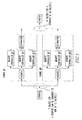
views, and more specifically to figure 7 thereof, there is shown
a switch 10 of a network 11. The switch 10 comprises a port card
12 for sending and receiving packets to and from the network 11.
The switch 10 comprises a plurality of fabrics 14 connected to the
port card 12. Each fabric switches portions of the packet. Each
fabric having a queue 16 in which portions of the packet are
stored. The switch 10 comprises a first dequeuer 18 for dequeueing
the portions of the packet. The switch 10 comprises a second
dequeuer 20 for dequeueing the portions of the packets. The switch
10 comprises a state machine 22 for controlling when the first and
second dequeuers dequeue the portions of the packet. It should be
noted that the use of "first" and "second" is for identifying
between the dequeuers and does not imply any order the dequeuers
operate in.
Preferably, the state machine 22 causes the first
dequeuer 18 to dequeue the portions of the packets first and then
the second dequeuer 20 to dequeue the portions of the packets. The
first dequeuer 18 and second dequeuer 20 preferably operate
independently of each other. Preferably, the queue 16, state
machine 22, and first and second dequeuers 20 are disposed in a
memory controller 24 of each fabric. Note, either the first or
second dequeuers can dequeue traffic first.
Each first dequeuer 18 of each fabric preferably dequeues
the portions of the packets in the queue 16 to which they are
connected synchronously with all the other first dequeuers in all
the other fabrics 14, and each second dequeuer 20 of each fabric
dequeues the portions of the packets in the queue 16 to which they
are connected synchronously with all the other second dequeuers 20
in all the other fabrics 14. Preferably, the fabric has an
aggregator 26 which receives portions of packets as stripes and
connects to the memory controller 24, and a separator 28 which
connects to the memory controller 24 and sends portions of the
packets as stripes to the port card 12.
The port card 12 preferably includes a striper 30 which
sends portions of packets as stripes to the aggregator 26 of each
fabric, and an unstriper 32 which receives portions of packets as
stripes from the separator 28 of each fabric. Preferably, the
state machine 22 controls the first and second dequeuers to
practice ABS.
The present invention pertains to a method for sending
packets with a switch 10 of a network 11. The method comprises the
steps of dequeueing with a first dequeuer 18 of a fabric portions
of a packet from a queue 16 of the fabric. Then there is the step
of dequeueing with a second dequeuer 20 of the fabric the portions
of the packet from the queue 16 after in the first dequeuer 18 has
dequeued the portions of the packet.
Preferably, before the dequeueing with the first dequeuer
18 step, there is the step of controlling with a state machine 22
of the fabric when the first and second dequeuers dequeue the
portions of the packet. The dequeueing with the second dequeuer 20
step preferably includes the step of dequeueing with a second
dequeuer 20 of the fabric the portions of the packet from the queue
16 after the first dequeuer 18 has dequeued the portions of the
packet independent of the operation of the first dequeuer 18.
Preferably, the dequeueing with the first dequeuer 18
step includes the step of dequeueing with the first dequeuer 18 the
portions of the packet synchronously with portions of packets in
queues 16 being dequeued by all other first dequeuers 18 in all the
other fabrics 14 to which the first dequeuers 18 are
correspondingly connected. Preferably, the dequeueing with the
second dequeuer 20 step includes the step of dequeueing with the
second dequeuer 20 the portions of the packet synchronously with
portions of packets in queues 16 being dequeued by all other second
dequeuers 20 in all other fabrics 14 to which the second dequeuers
20 are correspondingly connected.
The queue 16, state machine 22, and first and second
dequeuers are preferably disposed in a memory controller 24 of each
fabric, and before the dequeueing with the first dequeueing step
there is the step of receiving the portions of packets as stripes
at an aggregator 26 of the fabric which is connected to the memory
controller 24. Preferably, after the dequeueing with the first
dequeuer 18 step, there is the step of sending the portions of the
packets as stripes with a separator 28 of the fabric to a port card
12.
Before the controlling step, there are preferably the
steps of receiving packets at a striper 30 of the port card 12 and
sending portions of the packets as stripes to the aggregator 26 of
each fabric. Preferably, the sending the portions of the packets
as stripes with the separator 28 includes the step of sending the
portions of the packets as stripes with the separator 28 to an
unstriper 32 of the port card 12. The controlling step preferably
includes the step of controlling the first and second dequeuers to
practice ABS.
In the operation of the invention, APS involves a special
form of multicast. All traffic which goes to one output port must
be mirrored on the other port. APS and non-APS ports can be mixed.
The ports which are backing each other up may be physically
implemented on different hardware boards to allow for board
failure/replacement with APS providing support for user traffic to
continue with minimal disruption. If the APS ports are on
different boards, and there are multiple dequeuers, the APS port
pair can be spread across different dequeuers.
The following characteristics are desired for dequeueing
of APS ports:
Note that properties a and c generally work against each
other.
These characteristics are preserved by using an
implementation which allows one output dequeuer to be up to one
priority decision ahead of another output port. For this
discussion, the output ports will be notated Pa and Pb. This is
implemented by using a
state machine 22 shown below.
| Current state | Input | Next State | Comments |
| Pa=Pb | | | Initial state |
| Pa=Pb | Read PA with new priority | PA ahead | Port A is going ahead. Store priority decision so port B can follow. |
| Pa=Pb | Read Pb with new priority | PB ahead | Port B is ahead, store priority decision so port A can follow. |
| PA ahead | Read Pb and exhaust the current priority | PA ahead | Set the flag to the output dequeuer to act as if the queue associated with PA is empty. Port B will continue to dequeue. |
| PA ahead | Read Rb with new priority | Pa=Pb | New priority is determined by the priority chosen when PA was scheduled in the transition the PA ahead state |
| PB ahead | Read Pb and exhaust the current priority | PB ahead | Set the flag to the output dequeuer to act as if the queue associated with BA is empty. |
| PB ahead | Read Pa with new priority | Pa=Pb | New priority is determined by the priority chosen when PA was scheduled in the transition the PA ahead state |
This implementation needs a small number of bits per
output port (2 for state) and the ability to allocate two read
pointers per
queue 16, plus N bits of priority storage (2).
However, it has the following properties:
See U.S. patent application serial number 09/417,038
titled "Efficient Implementation of 1+1 Port Redundancy Through the
Use of ATM Multicast", incorporated by reference herein.
The switch uses RAID techniques to increase overall
switch bandwidth while minimizing individual fabric bandwidth. In
the switch architecture, all data is distributed evenly across all
fabrics so the switch adds bandwidth by adding fabrics and the
fabric need not increase its bandwidth capacity as the switch
increases bandwidth capacity.
Each fabric provides 40G of switching bandwidth and the
system supports 1, 2, 3, 4, 6, or 12 fabrics, exclusive of the
redundant/spare fabric. In other words, the switch can be a 40G,
80G, 120G, 160G, 240G, or 480G switch depending on how many fabrics
are installed.
A portcard provides 10G of port bandwidth. For every 4
portcards, there needs to be 1 fabric. The switch architecture
does not support arbitrary installations of portcards and fabrics.
The fabric ASICs support both cells and packets. As a
whole, the switch takes a "receiver make right" approach where the
egress path on ATM blades must segment frames to cells and the
egress path on frame blades must perform reassembly of cells into
packets.
There are currently eight switch ASICs that are used in
the switch:
There are 3 different views one can take of the
connections between the fabric: physical, logical, and "active."
Physically, the connections between the portcards and the fabrics
are all gigabit speed differential pair serial links. This is
strictly an implementation issue to reduce the number of signals
going over the backplane. The "active" perspective looks at a
single switch configuration, or it may be thought of as a snapshot
of how data is being processed at a given moment. The interface
between the fabric ASIC on the portcards and the fabrics is
effectively 12 bits wide. Those 12 bits are evenly distributed
("striped") across 1, 2, 3, 4, 6, or 12 fabrics based on how the
fabric ASICs are configured. The "active" perspective refers to the
number of bits being processed by each fabric in the current
configuration which is exactly 12 divided by the number of fabrics.
The logical perspective can be viewed as the union or max
function of all the possible active configurations. Fabric slot #1
can, depending on configuration, be processing 12, 6, 4, 3, 2, or
1 bits of the data from a single Striper and is therefore drawn
with a 12 bit bus. In contrast, fabric slot #3 can only be used to
process 4, 3, 2, or 1 bits from a single Striper and is therefore
drawn with a 4 bit bus.
Unlike previous switches, the switch really doesn't have
a concept of a software controllable fabric redundancy mode. The
fabric ASICs implement N+1 redundancy without any intervention as
long as the spare fabric is installed.
As far as what does it provide; N+1 redundancy means that
the hardware will automatically detect and correct a single failure
without the loss of any data.
The way the redundancy works is fairly simple, but to
make it even simpler to understand a specific case of a 120G switch
is used which has 3 fabrics (A, B, and C) plus a spare (S). The
Striper takes the 12 bit bus and first generates a checkword which
gets appended to the data unit (cell or frame). The data unit and
checkword are then split into a 4-bit-per-clock-cycle data stripe
for each of the A, B, and C fabrics (A3A2A1A0, B3B2B1B0, and C3C2C1C0).
These stripes are then used to produce the stripe for the spare
fabric S3S2S1S0 where Sn = An XOR Bn XOR Cn and these 4 stripes are
sent to their corresponding fabrics. On the other side of the
fabrics, the Unstriper receives 4 4-bit stripes from A, B, C, and
S. All possible combinations of 3 fabrics (ABC, ABS, ASC, and SBC)
are then used to reconstruct a "tentative" 12-bit data stream. A
checkword is then calculated for each of the 4 tentative streams
and the calculated checkword compared to the checkword at the end
of the data unit. If no error occurred in transit, then all 4
streams will have checkword matches and the ABC stream will be
forwarded to the Unstriper output. If a (single) error occurred,
only one checkword match will exist and the stream with the match
will be forwarded off chip and the Unstriper will identify the
faulty fabric stripe.
For different switch configurations, i.e. 1, 2, 4, 6, or
12 fabrics, the algorithm is the same but the stripe width changes.
If 2 fabrics fail, all data running through the switch
will almost certainly be corrupted.
The fabric slots are numbered and must be populated in
ascending order. Also, the spare fabric is a specific slot so
populating fabric slots 1, 2, 3, and 4 is different than populating
fabric slots 1, 2, 3, and the spare. The former is a 160G switch
without redundancy and the latter is 120G with redundancy.
Firstly, the ASICs are constructed and the backplane
connected such that the use of a certain portcard slots requires
there to be at least a certain minimum number of fabrics installed,
not including the spare. This relationship is shown in Table 0.
In addition, the APS redundancy within the switch is
limited to specifically paired portcards. Portcards 1 and 2 are
paired, 3 and 4 are paired, and so on through portcards 47 and 48.
This means that if APS redundancy is required, the paired slots
must be populated together.
To give a simple example, take a configuration with 2
portcards and only 1 fabric. If the user does not want to use APS
redundancy, then the 2 portcards can be installed in any two of
portcard slots 1 through 4. If APS redundancy is desired, then the
two portcards must be installed either in
slots 1 and 2 or
slots 3
and 4.
| Fabric Requirements for Portcard Slot Usage |
| Portcard Slot | Minimum # of Fabrics |
| 1-4 | 1 |
| 5-8 | 2 |
| 9-12 | 3 |
| 13-16 | 4 |
| 17-24 | 6 |
| 25-48 | 12 |
To add capacity, add the new fabric(s), wait for the
switch to recognize the change and reconfigure the system to stripe
across the new number of fabrics. Install the new portcards.
Note that it is not technically necessary to have the
full 4 portcards per fabric. The switch will work properly with 3
fabrics installed and a single portcard in slot 12. This isn't cost
efficient, but it will work.
To remove capacity, reverse the adding capacity
procedure.
If the switch is oversubscribed, i.e. install 8 portcards
and only one fabric.
It should only come about as the result of improperly
upgrading the switch or a system failure of some sort. The reality
is that one of two things will occur, depending on how this
situation arises. If the switch is configured as a 40G switch and
the portcards are added before the fabric, then the 5th through 8th
portcards will be dead. If the switch is configured as 80G non-redundant
switch and the second fabric fails or is removed then all
data through the switch will be corrupted (assuming the spare
fabric is not installed). And just to be complete, if 8 portcards
were installed in an 80G redundant switch and the second fabric
failed or was removed, then the switch would continue to operate
normally with the spare covering for the failed/removed fabric.
Figure 1 shows packet striping in the switch.
The chipset supports ATM and POS port cards in both OC48
and OC192c configurations. OC48 port cards interface to the
switching fabrics with four separate OC48 flows. OC192 port cards
logically combine the 4 channels into a 10G stream. The ingress
side of a port card does not perform traffic conversions for
traffic changing between ATM cells and packets. Whichever form of
traffic is received is sent to the switch fabrics. The switch
fabrics will mix packets and cells and then dequeue a mix of
packets and cells to the egress side of a port card.
The egress side of the port is responsible for converting
the traffic to the appropriate format for the output port. This
convention is referred to in the context of the switch as "receiver
makes right". A cell blade is responsible for segmentation of
packets and a cell blade is responsible for reassembly of cells
into packets. To support fabric speed-up, the egress side of the
port card supports a link bandwidth equal to twice the inbound side
of the port card.
The block diagram for a Poseidon-based ATM port card is
shown as in Figure 2. Each 2.5G channel consists of 4 ASICs:
Inbound TM and striper ASIC at the inbound side and unstriper ASIC
and outbound TM ASIC at the outbound side.
At the inbound side, OC-48c or 4 OC-12c interfaces are
aggregated. Each vortex sends a 2.5G cell stream into a dedicated
striper ASIC (using the BIB bus, as described below). The striper
converts the supplied routeword into two pieces. A portion of the
routeword is passed to the fabric to determine the output port(s)
for the cell. The entire routeword is also passed on the data
portion of the bus as a routeword for use by the outbound memory
controller. The first routeword is termed the "fabric routeword".
The routeword for the outbound memory controller is the "egress
routeword".
At the outbound side, the unstriper ASIC in each channel
takes traffic from each of the port cards, error checks and correct
the data and then sends correct packets out on its output bus. The
unstriper uses the data from the spare fabric and the checksum
inserted by the striper to detect and correct data corruption.
Figure 2 shows an OC48 Port Card.
The OC192 port card supports a single 10G stream to the
fabric and between a 10G and 20G egress stream. This board also
uses 4 stripers and 4 unstriper, but the 4 chips operate in
parallel on a wider data bus. The data sent to each fabric is
identical for both OC48 and OC192 ports so data can flow between
the port types without needing special conversion functions.
Figure 3 shows a 10G concatenated network blade.
Each 40G switch fabric enqueues up to 40Gbps cells/frames
and dequeue them at 80Gbps. This 2X speed-up reduces the amount of
traffic buffered at the fabric and lets the outbound ASIC digest
bursts of traffic well above line rate. A switch fabric consists of
three kinds of ASICs: aggregators, memory controllers, and
separators. Nine aggregator ASICs receive 40Gbps of traffic from up
to 48 network blades and the control port. The aggregator ASICs
combine the fabric route word and payload into a single data stream
and TDM between its sources and places the resulting data on a wide
output bus. An additional control bus (destid) is used to control
how the memory controllers enqueue the data. The data stream from
each aggregator ASIC then bit sliced into 12 memory controllers.
The memory controller receives up to 16 cells/frames
every clock cycle. Each of 12 ASICs stores 1/12 of the aggregated
data streams. It then stores the incoming data based on control
information received on the destid bus. Storage of data is
simplified in the memory controller to be relatively unaware of
packet boundaries (cache line concept). All 12 ASICs dequeue the
stored cells simultaneously at aggregated speed of 80Gbps.
Nine separator ASICs perform the reverse function of the
aggregator ASICs. Each separator receives data from all 12 memory
controllers and decodes the routewords embedded in the data streams
by the aggregator to find packet boundaries. Each separator ASIC
then sends the data to up to 24 different unstripers depending on
the exact destination indicated by the memory controller as data
was being passed to the separator.
The dequeue process is back-pressure driven. If
back-pressure is applied to the unstriper, that back-pressure is
communicated back to the separator. The separator and memory
controllers also have a back-pressure mechanism which controls when
a memory controller can dequeue traffic to an output port.
In order to support OC48 and OC192 efficiently in the
chipset, the 4 OC48 ports from one port card are always routed to
the same aggregator and from the same separator (the port
connections for the aggregator & Sep are always symmetric).
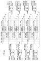
Figures 4a and 4b show the connectivity of the fabric
ASICs.
The external interfaces of the switches are the Input Bus
(BIB) between the striper ASIC and the ingress blade ASIC such as
Vortex and the Output Bus (BOB) between the unstriper ASIC and the
egress blade ASIC such as Trident.
The Striper ASIC accepts data from the ingress port via
the Input Bus (BIB) (also known as DIN_ST_bl_ch bus).
This bus can either operate as 4 separate 32 bit input
busses (4xOC48c) or a single 128 bit wide data bus with a common
set of control lines to all stripers. This bus supports either
cells or packets based on software configuration of the striper
chip.
The unstriper ASIC sends data to the egress port via
Output Bus (BOB) (also known as DOUT_UN_bl_ch bus), which is a 64
(or 256) bit data bus that can support either cell or packet. It
consists of the following signals:
This bus can either operate as 4 separate 32 bit output
busses (4xOC48c) or a single 128 bit wide data bus with a common
set of control lines from all Unstripers. This bus supports either
cells or packets based on software configuration of the unstriper
chip.
The Synchronizer has two main purposes. The first
purpose is to maintain logical cell/packet or datagram ordering
across all fabrics. On the fabric ingress interface, datagrams
arriving at more than one fabric from one port card's channels need
to be processed in the same order across all fabrics. The
Synchronizer's second purpose is to have a port card's egress
channel re-assemble all segments or stripes of a datagram that
belong together even though the datagram segments are being sent
from more than one fabric and can arrive at the blade's egress
inputs at different times. This mechanism needs to be maintained in
a system that will have different net delays and varying amounts of
clock drift between blades and fabrics.
The switch uses a system of a synchronized windows where
start information is transmit around the system. Each transmitter
and receiver can look at relative clock counts from the last
resynch indication to synchronize data from multiple sources. The
receiver will delay the receipt of data which is the first clock
cycle of data in a synch period until a programmable delay after it
receives the global synch indication. At this point, all data is
considered to have been received simultaneously and fixed ordering
is applied. Even though the delays for packet 0 and cell 0 caused
them to be seen at the receivers in different orders due to delays
through the box, the resulting ordering of both streams at receive
time = 1 is the same, Packet 0, Cell 0 based on the physical bus
from which they were received.
Multiple cells or packets can be sent in one counter
tick. All destinations will order all cells from the first
interface before moving onto the second interface and so on. This
cell synchronization technique is used on all cell interfaces.
Differing resolutions are required on some interfaces.
The Synchronizer consists of two main blocks, mainly, the
transmitter and receiver. The transmitter block will reside in the
Striper and Separator ASICs and the receiver block will reside in
the Aggregator and Unstriper ASICs. The receiver in the Aggregator
will handle up to 24(6 port cards x 4 channels) input lanes. The
receiver in the Unstriper will handle up to 13 (12 fabrics + 1
parity fabric) input lanes.
When a sync pulse is received, the transmitter first
calculates the number of clock cycles it is fast (denoted as N
clocks).
The transmit synchronizer will interrupt the output
stream and transmit N K characters indicating it is locking down.
At the end of the lockdown sequence, the transmitter transmits a K
character indicating that valid data will start on the next clock
cycle. This next cycle valid indication is used by the receivers
to synchronize traffic from all sources.
At the next end of transfer, the transmitter will then
insert at least one idle on the interface. These idles allow the
10 bit decoders to correctly resynchronize to the 10 bit serial
code window if they fall out of synch.
The receive synchronizer receives the global synch pulse
and delays the synch pulse by a programmed number (which is
programmed based on the maximum amount of transport delay a
physical box can have). After delaying the synch pulse, the
receiver will then consider the clock cycle immediately after the
synch character to be eligible to be received. Data is then
received every clock cycle until the next synch character is seen
on the input stream. This data is not considered to be eligible
for receipt until the delayed global synch pulse is seen.
Since transmitters and receivers will be on different
physical boards and clocked by different oscillators, clock speed
differences will exist between them. To bound the number of clock
cycles between different transmitters and receivers, a global sync
pulse is used at the system level to resynchronize all sequence
counters. Each chip is programmed to ensure that under all valid
clock skews, each transmitter and receiver will think that it is
fast by at least one clock cycle. Each chip then waits for the
appropriate number of clock cycles they are into their current
sync_pulse_window. This ensure that all sources run N*
sync_pulse_window valid clock cycles between synch pulses.
As an example, the synch pulse window could be programmed
to 100 clocks, and the synch pulses sent out at a nominal rate of
a synch pulse every 10,000 clocks. Based on a worst case drifts
for both the synch pulse transmitter clocks and the synch pulse
receiver clocks, there may actually be 9,995 to 10,005 clocks at
the receiver for 10,000 clocks on the synch pulse transmitter. In
this case, the synch pulse transmitter would be programmed to send
out synch pulses every 10,006 clock cycles. The 10,006 clocks
guarantees that all receivers must be in their next window. A
receiver with a fast clock may have actually seen 10,012 clocks if
the synch pulse transmitter has a slow clock. Since the synch
pulse was received 12 clock cycles into the synch pulse window, the
chip would delay for 12 clock cycles. Another receiver could seen
10,006 clocks and lock down for 6 clock cycles at the end of the
synch pulse window. In both cases, each source ran 10,100 clock
cycles.
When a port card or fabric is not present or has just
been inserted and either of them is supposed to be driving the
inputs of a receive synchronizer, the writing of data to the
particular input FIFO will be inhibited since the input clock will
not be present or unstable and the status of the data lines will be
unknown. When the port card or fabric is inserted, software must
come in and enable the input to the byte lane to allow data from
that source to be enabled. Writes to the input FIFO will be
enabled. It is assumed that, the enable signal will be asserted
after the data, routeword and clock from the port card or fabric
are stable.
At a system level, there will be a primary and secondary
sync pulse transmitter residing on two separate fabrics. There
will also be a sync pulse receiver on each fabric and blade. This
can be seen in Figure 5. A primary sync pulse transmitters will be
a free-running sync pulse generator and a secondary sync pulse
transmitter will synchronize its sync pulse to the primary. The
sync pulse receivers will receive both primary and secondary sync
pulses and based on an error checking algorithm, will select the
correct sync pulse to forward on to the ASICs residing on that
board. The sync pulse receiver will guarantee that a sync pulse is
only forwarded to the rest of the board if the sync pulse from the
sync pulse transmitters falls within its own sequence "0" count.
For example, the sync pulse receiver and an Unstriper ASIC will
both reside on the same Blade. The sync pulse receiver and the
receive synchronizer in the Unstriper will be clocked from the same
crystal oscillator, so no clock drift should be present between the
clocks used to increment the internal sequence counters. The
receive synchronizer will require that the sync pulse it receives
will always reside in the "0" count window.
If the sync pulse receiver determines that the primary
sync pulse transmitter is out of sync, it will switch over to the
secondary sync pulse transmitter source. The secondary sync pulse
transmitter will also determine that the primary sync pulse
transmitter is out of sync and will start generating its own sync
pulse independently of the primary sync pulse transmitter. This is
the secondary sync pulse transmitter's primary mode of operation.
If the sync pulse receiver determines that the primary sync pulse
transmitter has become in sync once again, it will switch to the
primary side. The secondary sync pulse transmitter will also
determine that the primary sync pulse transmitter has become in
sync once again and will switch back to a secondary mode. In the
secondary mode, it will sync up its own sync pulse to the primary
sync pulse. The sync pulse receiver will have less tolerance in
its sync pulse filtering mechanism than the secondary sync pulse
transmitter. The sync pulse receiver will switch over more quickly
than the secondary sync pulse transmitter. This is done to ensure
that all receiver synchronizers will have switched over to using
the secondary sync pulse transmitter source before the secondary
sync pulse transmitter switches over to a primary mode.
Figure 5 shows sync pulse distribution.
In order to lockdown the backplane transmission from a
fabric by the number of clock cycles indicated in the sync calculation,
the entire fabric must effectively freeze for that many
clock cycles to ensure that the same enqueuing and dequeueing
decisions stay in sync. This requires support in each of the
fabric ASICs. Lockdown stops all functionality, including special
functions like queue resynch.
The sync signal from the synch pulse receiver is
distributed to all ASICs. Each fabric ASIC contains a counter in
the core clock domain that counts clock cycles between global sync
pulses. After the sync pulse is received, each ASIC calculates the
number of clock cycles it is fast. Because the global sync is not
transferred with its own clock, the calculated lockdown cycle value
may not be the same for all ASICs on the same fabric. This
difference is accounted for by keeping all interface FIFOs at a
depth where they can tolerate the maximum skew of lockdown counts.
Lockdown cycles on all chips are always inserted at the
same logical point relative to the beginning of the last sequence
of "useful" (non-lockdown) cycles. That is, every chip will always
execute the same number of "useful" cycles between lockdown events,
even though the number of lockdown cycles varies.
Lockdown may occur at different times on different chips.
All fabric input FIFOs are initially set up such that lockdown can
occur on either side of the FIFO first without the FIFO running dry
or overflowing. On each chip-chip interface, there is a sync FIFO
to account for lockdown cycles (as well as board trace lengths and
clock skews). The transmitter signals lockdown while it is locked
down. The receiver does not push during indicated cycles, and does
not pop during its own lockdown. The FIFO depth will vary
depending on which chip locks down first, but the variation is
bounded by the maximum number of lockdown cycles. The number of
lockdown cycles a particular chip sees during one global sync
period may vary, but they will all have the same number of useful
cycles. The total number of lockdown cycles each chip on a
particular fabric sees will be the same, within a bounded
tolerance.
The Aggregator core clock domain completely stops for the
lockdown duration - all flops and memory hold their state. Input
FIFOs are allowed to build up. Lockdown bus cycles are inserted in
the output queues. Exactly when the core lockdown is executed is
dictated by when DOUT_AG bus protocol allows lockdown cycles to be
inserted. DOUT_AG lockdown cycles are indicated on the DestID bus.
The memory controller must lockdown all flops for the
appropriate number of cycles. To reduce impact to the silicon area
in the memory controller, a technique called propagated lockdown is
used.
The on-fabric chip-to-chip synchronization is executed at
every sync pulse. While some sync error detecting capability may
exist in some of the ASICs, it is the Unstriper's job to detect
fabric synchronization errors and to remove the offending fabric.
The chip-to-chip synchronization is a cascaded function that is
done before any packet flow is enabled on the fabric. The
synchronization flows from the Aggregator to the Memory Controller,
to the Separator, and back to the Memory Controller. After the
system reset, the Aggregators wait for the first global sync
signal. When received, each Aggregator transmits a local sync
command (value 0x2) on the DestID bus to each Memory Controller.
The striping function assigns bits from incoming data
streams to individual fabrics. Two items were optimized in deriving
the striping assignment:
These were traded off against additional muxing legs for
the striper and unstriper ASICs. Irregardless of the optimization,
the switch must have the same data format in the memory controller
for both OC48 and OC192.
Backplane efficiency requires that minimal padding be
added when forming the backplane busses. Given the 12 bit backplane
bus for OC48 and the 48 bit backplane bus for OC192, an optimal
assignment requires that the number of unused bits for a transfer
to be equal to (number_of_bytes *8)/bus_width where "/" is integer
division. For OC48, the bus can have 0, 4 or 8 unutilized bits. For
OC192 the bus can have 0, 8, 16, 24, 32, or 40 unutilized bits.
This means that no bit can shift between 12 bit
boundaries or else OC48 padding will not be optimal for certain
packet lengths.
For OC192c, maximum bandwidth utilization means that each
striper must receive the same number of bits (which implies bit
interleaving into the stripers). When combined with the same
backplane interconnection, this implies that in OC192c, each stripe
must have exactly the correct number of bits come from each striper
which has 1/4 of the bits.
For the purpose of assigning data bits to fabrics, a 48
bit frame is used. Inside the striper is a FIFO which is written 32
bits wide at 80-100 MHz and read 24 bits wide at 125 MHz. Three 32
bit words will yield four 24 bit words. Each pair of 24 bit words
is treated as a 48 bit frame. The assignments between bits and
fabrics depends on the number of fabrics.
| Bit striping function |
| | | Fab0 | Fab 1 | Fab 2 | Fab 3 | Fab 4 | Fab 5 | Fab 6 | Fab 7 | Fab 8 | Fab 9 | Fab 10 | Fab 11 |
| | 0:11 | 0:11 |
| 1 fab | 12:23 | 12:23 |
| | 24:35 | 24:35 |
| | 36:47 | 36:47 |
| | 0:11 | 0,2,5 ,7,8,10 | 1,3,4, 6,9,11 |
| 2 fab | 12:23 | 13,15, 16,18, 21 | 12,14, 17,19, 20,22 |
| | 24:35 | +24 to 0:11 | +24 to 0:11 |
| | 36:47 | +24 to 12:23 | +24 to 12:23 |
| | 0:11 | 0,3,5, 10 | 2,4,7, 9 | 1,6,8, 11 |
| 3 fab | 12:23 | 15,17, 22,13 | 14, 16, 19,21 | 13, 18, 20,23 |
| | 24:35 | +24 to 0:11 | +24 to 0:11 | +24 to 0:11 |
| | 36:47 | +24 to 12:23 | +24 to 12:23 | +24 to 12:23 |
| | 0:11 | 0,5,10 | 3,4,9 | 2,7,8 | 1,6,11 |
| 4 fab | 12:23 | 15,16, 21 | 14,19, 20 | 13,18, 23 | 12,17,22 |
| | 24:35 | 26,31, 32 | 25,30, 35 | 24,29, 34' | 27,28, 33 |
| | 36:47 | 37,42, 47 | 36,41, 46 | 39,40, 43 | 38,43, 44 |
| | 0:11 | 0,11 | 1,4 | 5,8 | 2,9 | 3,6 | 7,10 |
| 6 fab | 12:23 | 14,21 | 15,18 | 19,22 | 12,23 | 13,16 | 17,20 |
| | 24:35 | +24 to 0:11 |
| | 36:47 | +24 to 12:23 |
| | 0:11 | 0 | 4 | 8 | 1 | 5 | 9 | 2 | 6 | 10 | 3 | 7 | 11 |
| 12 fab | 12:23 | 15 | 19 | 23 | 12 | 16 | 20 | 13 | 17 | 21 | 14 | 18 | 22 |
| | 24:35 | 26 | 30 | 34 | 27 | 31 | 35 | 24 | 28 | 32 | 25 | 29 | 33 |
| | 36:47 | 37 | 41 | 45 | 38 | 42 | 46 | 39 | 43 | 47 | 37 | 40 | 44 |
The following tables give the byte lanes which are read
first in the aggregator and written to first in the separator. The
four channels are notated A,B,C,D. The different fabrics have
different read/write order of the channels to allow for all busses
to be fully utilized.
One fabric-40G
The next table gives the interface read order for the
aggregator.
| Fabric | 1st | 2nd | 3rd | 4th |
| 0 | A | B | C | D |
| Par | A | B | C | D |
| Fabric |
1st |
2nd |
3rd |
4th |
| 0 |
A |
C |
B |
D |
| 1 |
B |
D |
A |
C |
| Par |
A |
C |
B |
D |
120G
| Fabric |
1st |
2nd |
3rd |
4th |
| 0 |
A |
D |
B |
C |
| 1 |
C |
A |
D |
B |
| 2 |
B |
C |
A |
D |
| Par |
A |
D |
B |
C |
Three fabric-160G
| Fabric |
1st |
2nd |
3rd |
4th |
| 0 |
A |
B |
C |
D |
| 1 |
D |
A |
B |
C |
| 2 |
C |
D |
A |
B |
| 3 |
B |
C |
D |
A |
| Par |
A |
B |
C |
D |
Siz fabric-240 G
| Fabric |
1st |
2nd |
3rd |
4th |
| 0 |
A |
D |
C |
B |
| 1 |
B |
A |
D |
C |
| 2 |
B |
A |
D |
C |
| 3 |
C |
B |
A |
D |
| 4 |
D |
C |
B |
A |
| 5 |
D |
C |
B |
A |
| Par |
A |
C |
D |
B |
Twelve Fabric-480 G
| Fabric |
1st |
2nd |
3rd | 4th | |
| 0,1,2 |
A |
D | C |
B | | |
| 3,4,5 |
B |
A | D |
C | | |
| 6,7,8 |
C |
B | A |
D | | |
| 9,10,11 |
D |
C |
B |
A |
| Par |
A |
B |
C |
D |
Interfaces to the gigabit transceivers will utilize the
transceiver bus as a split bus with two separate routeword and data
busses. The routeword bus will be a fixed size (2 bits for OC48
ingress, 4 bits for OC48 egress, 8 bits for OC192 ingress and 16
bits for OC192 egress), the data bus is a variable sized bus. The
transmit order will always have routeword bits at fixed locations.
Every striping configuration has one transceiver that it used to
talk to a destination in all valid configurations. That
transceiver will be used to send both routeword busses and to start
sending the data.
The backplane interface is physically implemented using
interfaces to the backplane transceivers. The bus for both ingress
and egress is viewed as being composed of two halves, each with
routeword data. The two bus halves may have information on
separate packets if the first bus half ends a packet.
For example, an OC48 interface going to the fabrics
locally speaking has 24 data bits and 2 routeword bits. This bus
will be utilized acting as if it has 2x (12 bit data bus + 1 bit
routeword bus). The two bus halves are referred to as A and B.
Bus A is the first data, followed by bus B. A packet can start on
either bus A or B and end on either bus A or B.
In mapping data bits and routeword bits to transceiver
bits, the bus bits are interleaved. This ensures that all
transceivers should have the same valid/invalid status, even if the
striping amount changes. Routewords should be interpreted with bus
A appearing before bus B.
The bus A/Bus B concept closely corresponds to having
interfaces between chips.
All backplane busses support fragmentation of data. The
protocol used marks the last transfer (via the final segment bit in
the routeword). All transfers which are not final segment need to
utilize the entire bus width, even if that is not an even number of
bytes. Any given packet must be striped to the same number of
fabrics for all transfers of that packet. If the striping amount
is updated in the striper during transmission of a packet, it will
only update the striping at the beginning of the next packet.
Each transmitter on the ASICs will have the following I/O
for each channel:
8 bit data bus, 1 bit clock, 1 bit control.
On the receive side, for channel the ASIC receives
a receive clock, 8 bit data bus, 3 bit status bus.
The switch optimizes the transceivers by mapping a
transmitter to between 1 and 3 backplane pairs and each receiver
with between 1 and 3 backplane pairs. This allows only enough
transmitters to support traffic needed in a configuration to be
populated on the board while maintaining a complete set of
backplane nets. The motivation for this optimization was to reduce
the number of transceivers needed.
The optimization was done while still requiring that at
any time, two different striping amounts must be supported in the
gigabit transceivers. This allows traffic to be enqueued from a
striping data to one fabric and a striper striping data to two
fabrics at the same time.
Depending on the bus configuration, multiple channels may
need to be concatenated together to form one larger bandwidth pipe
(any time there is more than one transceiver in a logical
connection). Although quad gbit transceivers can tie 4 channels
together, this functionality is not used. Instead the receiving
ASIC is responsible for synchronizing between the channels from one
source. This is done in the same context as the generic
synchronization algorithm.
The 8b/10b encoding/decoding in the gigabit transceivers
allow a number of control events to be sent over the channel. The
notation for these control events are K characters and they are
numbered based on the encoded 10 bit value. Several of these K
characters are used in the chipset. The K characters used and
their functions are given in the table below.
| K Character usage |
| K character | Function | Notes |
| 28.0 | Sync indication | Transmitted after lockdown cycles, treated as the prime synchronization event at the receivers |
| 28.1 | Lockdown | Transmitted during lockdown cycles on the backplane |
| 28.2 | Packet Abort | Transmitted to indicate the card is unable to finish the current packet. Current use is limited to a port card being pulled while transmitting traffic |
| 28.3' | Resynch window | Transmitted by the striper at the start of a synch window if a resynch will be contained in the current sync window |
| 28.4 | BP set | Transmitted by the striper if the bus is currently idle and the value of the bp bit must be set. |
| 28.5 | Idle | Indicates idle condition |
| 28.6 | BP clr | Transmitted by the striper if the bus is currently idle and the bp bit must be cleared. |
The switch has a variable number of data bits supported
to each backplane channel depending on the striping configuration
for a packet. Within a set of transceivers, data is filled in the
following order:
F[fabric]_[oc192 port number] [oc48 port designation
(a,b,c,d)][transceiver_number]
The chipset implements certain functions which are
described here. Most of the functions mentioned here have support
in multiple ASICs, so documenting them on an ASIC by ASIC basis
does not give a clear understanding of the full scope of the
functions required.
The switch chipset is architected to work with packets up
to 64K + 6 bytes long. On the ingress side of the switch, there
are busses which are shared between multiple ports. For most
packets, they are transmitted without any break from the start of
packet to end of packet. However, this approach can lead to large
delay variations for delay sensitive traffic. To allow delay
sensitive traffic and long traffic to coexist on the same switch
fabric, the concept of long packets is introduced. Basically long
packets allow chunks of data to be sent to the queueing location,
built up at the queueing location on a source basis and then added
into the queue all at once when the end of the long packet is
transferred. The definition of a long packet is based on the
number of bits on each fabric.
If the switch is running in an environment where Ethernet
MTU is maintained throughout the network, long packets will not be
seen in a switch greater than 40G in size.
A wide cache-line shared memory technique is used to
store cells/packets in the port/priority queues. The shared memory
stores cells/packets continuously so that there is virtually no
fragmentation and bandwidth waste in the shared memory.
There exists multiple queues in the shared memory. They
are per-destination and priority based. All cells/packets which
have the same output priority and blade/channel ID are stored in
the same queue. Cells are always dequeued from the head of the
list and enqueued into the tail of the queue. Each cell/packet
consists of a portion of the egress route word, a packet length,
and variable-length packet data. Cell and packets are stored
continuously, i.e., the memory controller itself does not recognize
the boundaries of cells/packets for the unicast connections. The
packet length is stored for MC packets.
The multicast port mask memory 64Kx16-bit is used to
store the destination port mask for the multicast connections, one
entry (or multiple entries) per multicast VC. The port masks of the
head multicast connections indicated by the multicast DestID FIFOs
are stored internally for the scheduling reference. The port mask
memory is retrieved when the port mask of head connection is
cleaned and a new head connection is provided.
APS stands for a Automatic Protection Switching, which is
a SONET redundancy standard. To support APS feature in the switch,
two output ports on two different port cards send roughly the same
traffic. The memory controllers maintain one set of queues for an
APS port and send duplicate data to both output ports.
To support data duplication in the memory controller
ASIC, each one of multiple unicast queues has a programmable APS
bit. If the APS bit is set to one, a packet is dequeued to both
output ports. If the APS bit is set to zero for a port, the
unicast queue cperates at the normal mode. If a port is configured
as an APS slave, then it will read from the queues of the APS
master port. For OC48 ports, the APS port is always on the same
OC48 port on the adjacent port card.
The shared memory queues in the memory controllers among
the fabrics might be out of sync (i.e., same queues among different
memory controller ASICs have different depths) due to clock drifts
or a newly inserted fabric. It is important to bring the fabric
queues to the valid and sync states from any arbitrary states. It
is also desirable not to drop cells for any recovery mechanism.
A resynch cell is broadcast to all fabrics (new and
existing) to enter the resynch state. Fabrics will attempt to drain
all of the traffic received before the resynch cell before queue
resynch ends, but no traffic received after the resynch cell is
drained until queue resynch ends. A queue resynch ends when one of
two events happens:
At the end of queue resynch, all memory controllers will
flush any left-over old traffic (traffic received before the queue
resynch cell). The freeing operation is fast enough to guarantee
that all memory controllers can fill all of memory no matter when
the resynch state was entered.
Queue resynch impacts all 3 fabric ASICs. The
aggregators must ensure that the FIFOs drain identically after a
queue resynch cell. The memory controllers implement the queueing
and dropping. The separators need to handle memory controllers
dropping traffic and resetting the length parsing state machines
when this happens. For details on support of queue resynch in
individual ASICs, refer to the chip ADSs.
For the dequeue side, multicast connections have
independent 32 tokens per port, each worth up 50-bit data or a
complete packet. The head connection and its port mask of a higher
priority queue is read out from the connection FIFO and the port
mask memory every cycle. A complete packet is isolated from the
multicast cache line based on the length field of the head
connection. The head packet is sent to all its destination ports.
The 8 queue drainers transmit the packet to the separators when
there are non-zero multicast tokens are available for the ports.
Next head connection will be processed only when the current head
packet is sent out to all its ports.
Queue structure can be changed on fly through the fabric
resynch cell where the number of priority per port field is used to
indicate how many priority queues each port has. The stripper ASIC
resides on the network blade.
The following words have reasonably specific meanings in
the vocabulary of the switch. Many are mentioned elsewhere, but
this is an attempt to bring them together in one place with
definitions.
| Word | Meaning |
| APS | Automatic Protection Switching. A sonet/sdh standard for implementing redundancy on physical links. For the switch, APS is used to also recover from any detected port card failures. |
| Backplane synch | A generic term referring either to the general process the switch boards use to account for varying transport delays between boards and clock drift or to the logic which implements the TX/RX functionality required for the switch ASICs to account for varying transport delays and clock drifts. |
| BIB | The switch input bus. The bus which is used to pass data to the striper(s). See also BOB |
| Blade | Another term used for a port card. References to blades should have been eliminated from this document, but some may persist. |
| BOB | The switch output bus. The output bus from the striper which connects to the egress memory controller. See also BIB. |
| Egress Routeword | This is the routeword which is supplied to the chip after the unstriper. From an internal chipset perspective, the egress routeword is treated as data. See also fabric routeword. |
| Fabric | Routeword used by the fabric to determine the output queue. This routeword is not passed outside |
| Routeword | the unstriper. A significant portion of this routeword is blown away in the fabrics. |
| Freeze | Having logic maintain its values during lock-down cycles. |
| Lock-down | Period of time where the fabric effectively stops performing any work to compensate for clock drift. If the backplane synchronization logic determines that a fabric is 8 clock cycles fast, the fabric will lock down for 8 clocks. |
| Queue Resynch | A queue resynch is a series of steps executed to ensure that the logical state of all fabric queues for all ports is identical at one logical point in time. Queue resynch is not tied to backplane resynch (including lock- down) in any fashion, except that a lock-down can occur during a queue resynch. |
| SIB | Striped input bus. A largely obsolete term used to describe the output bus from the striper and input bus to the aggregator. |
| SOB | The first is striped output bus, which is the output bus of the fabric and the input bus of the agg. See also SIB. |
| Sync | Depends heavily on context. Related terms are queue resynch, lock-down, freeze, and backplane sync. |
| Wacking | The implicit bit steering which occurs in the OC 192 ingress stage since data is bit interleaved among stripers. This bit steering is reversed by the aggregators. |
The relationship between the transmit and receive
counters can be seen in figure 6.
Although the invention has been described in detail in
the foregoing embodiments for the purpose of illustration, it is to
be understood that such detail is solely for that purpose and that
variations can be made therein by those skilled in the art without
departing from the spirit and scope of the invention except as it
may be described by the following claims.