EP1202443A2 - Transformer/rectifier for aircraft ground power unit - Google Patents
Transformer/rectifier for aircraft ground power unit Download PDFInfo
- Publication number
- EP1202443A2 EP1202443A2 EP01308681A EP01308681A EP1202443A2 EP 1202443 A2 EP1202443 A2 EP 1202443A2 EP 01308681 A EP01308681 A EP 01308681A EP 01308681 A EP01308681 A EP 01308681A EP 1202443 A2 EP1202443 A2 EP 1202443A2
- Authority
- EP
- European Patent Office
- Prior art keywords
- phase
- power
- primary winding
- transformer
- sides
- Prior art date
- Legal status (The legal status is an assumption and is not a legal conclusion. Google has not performed a legal analysis and makes no representation as to the accuracy of the status listed.)
- Withdrawn
Links
Images



Classifications
-
- H—ELECTRICITY
- H02—GENERATION; CONVERSION OR DISTRIBUTION OF ELECTRIC POWER
- H02M—APPARATUS FOR CONVERSION BETWEEN AC AND AC, BETWEEN AC AND DC, OR BETWEEN DC AND DC, AND FOR USE WITH MAINS OR SIMILAR POWER SUPPLY SYSTEMS; CONVERSION OF DC OR AC INPUT POWER INTO SURGE OUTPUT POWER; CONTROL OR REGULATION THEREOF
- H02M7/00—Conversion of AC power input into DC power output; Conversion of DC power input into AC power output
- H02M7/02—Conversion of AC power input into DC power output without possibility of reversal
- H02M7/04—Conversion of AC power input into DC power output without possibility of reversal by static converters
- H02M7/12—Conversion of AC power input into DC power output without possibility of reversal by static converters using discharge tubes with control electrode or semiconductor devices with control electrode
- H02M7/21—Conversion of AC power input into DC power output without possibility of reversal by static converters using discharge tubes with control electrode or semiconductor devices with control electrode using devices of a triode or transistor type requiring continuous application of a control signal
- H02M7/217—Conversion of AC power input into DC power output without possibility of reversal by static converters using discharge tubes with control electrode or semiconductor devices with control electrode using devices of a triode or transistor type requiring continuous application of a control signal using semiconductor devices only
- H02M7/23—Conversion of AC power input into DC power output without possibility of reversal by static converters using discharge tubes with control electrode or semiconductor devices with control electrode using devices of a triode or transistor type requiring continuous application of a control signal using semiconductor devices only arranged for operation in parallel
Definitions
- the present invention relates generally to aircraft ground power units and transformer/rectifier systems used in such units for converting 3-phase ac input into a substantially stable dc output and, more particularly, to a transformer/rectifier arrangement which provides reduced voltage drops across diodes in high output current systems.
- Aircraft ground power units are utilized to power aircraft when on the ground. Larger aircraft tend to utilize ground power units which output ac power while smaller aircraft tend to utilize ground power units which output dc power, typically at about 28 volts and in the range of several hundred amps.
- the dc power may be developed from a 3-phase ac source such as a static converter or a generator. In either case a transformer/rectifier arrangement may be used to convert the 3-phase ac power to the desired dc output.
- FIG. 1 shows a full wave center tap connection 12 with 6 pulse rectification of a 3-phase (A, B, C) input.
- the 3 input phases A, B, and C are connected in a STAR (Y) configuration 14 and share a common neutral connection 16, and a single 3-phase transformer 18 defined by one magnetic member can be used for coupling the primary windings 20A, 20B, 20C to the secondary windings 22A, 22B, 22C.
- each side of each secondary winding connects to the anode side of a respective diode 24 (dl - d6) to provide the 6 pulse rectification.
- Notable characteristics of this arrangement are (1) that only one diode 24 conducts at any one time such that each diode conducts for 60 electrical degrees with its peak current equal to the dc load current and (2) the current rating of each transformer secondary winding is 0.408 times the dc load current.
- Characteristic (1) is undesired when high current systems are implemented because the voltage drop across the diodes can be significant.
- Characteristic (2) influences the size of the transformer because the higher the current through the secondary windings, the greater the cross-section of the wire needed to form the secondary winding of the transformer.
- an aircraft ground power unit includes a transformer/rectifier arrangement for converting 3-phase ac power to dc power.
- the transformer/rectifier arrangement includes an A-phase transformer formed by an A-phase magnetic member, an A-phase primary winding having first and second sides, and an A-phase secondary winding; a B-phase transformer formed by a B-phase magnetic member, a B-phase primary winding having first and second sides, and a B-phase secondary winding; and a C-phase transformer formed by a C-phase magnetic member, a C-phase primary winding having first and second sides, and a C-phase secondary winding.
- the A-phase primary winding first side is connected to receive A-phase power
- the B-phase primary winding first side is connected to receive B-phase power
- the C-phase primary winding first side is connected to receive C-phase power.
- the A-phase primary winding second side, B-phase primary winding second side and C-phase primary winding second side are connected together for delivering current traveling out of one of the second sides into at least one of the other second sides.
- the A-phase, B-phase, and C-phase secondary windings are arranged in a full wave center-tap transformer output connection which includes an output for delivering current to a load when connected thereto.
- the center-tap configuration includes six diodes, two diodes conduct at any one time, the peak dc current through each diode is limited to 1 ⁇ 2 the dc current delivered to the load, and the current rating of each secondary winding is 0.286 times the dc current delivered to the load.
- a transformer/rectifier arrangement 50 including a primary side 52 and secondary side 54.
- Three distinct magnetic members 56A, 56B, and 56C couple the primary side 52 to the secondary side 54.
- the primary side 52 includes primary windings 58A, 58B, and 58C each associated with one corresponding magnetic member 56A, 56B, 56C.
- the secondary side 54 includes secondary windings 60A, 60B, and 60C each associated with one corresponding magnetic member.
- three separate single-phase transformers 62A, 62B and 62C are formed.
- one side 64A, 64B, 64C of each primary winding 58A, 58B and 58C is connected to receive ac power from a respective A-phase source 66A, B-phase source 66B and C-phase source 66C.
- the other side 68A, 68B, 68C of each primary winding 58A, 58B and 58C are connected in common. This configuration provides that current flowing out of primary winding 58A through side 68A, for example, is directed into one of the other primary windings 58B or 58C through its associated side 68B or 68C.
- current flowing out of primary winding 58B through side 68B is directed into one of the other primary windings 58A or 58C through its associated side 68A or 68C
- current flowing out of primary winding 58C through side 68C is directed into one of the other primary windings 58A or 58B through its associated side 68A or 68B.
- the illustrated configuration is a STAR (Y) configuration with no neutral connection.
- each secondary winding 60A, 60B and 60C includes a respective center-tap 70A, 70B, 70C to common.
- Secondary winding 60A includes sides 72A and 74A which each connect to the anode side of respective diodes D1 and D2.
- Secondary winding 60B includes sides 72B and 74B which each connect to the anode side of respective diodes D3 and D4, and
- secondary winding 60C includes sides 72C and 74C which each connect to the anode side of respective diodes D5 and D6.
- the cathode sides of diodes D1 - D6 are connected to a common node 76 which defines an output through which current, I DC is delivered to a load 78 when connected thereto.
- the graph 80 of Fig. 3 shows the relative timing and amplitude of currents delivered to each of the primary windings 58A, 58B, and 58C, to each of the diodes D1, D2, D3, D4, D5 and D6 current, and to the load 78.
- two diodes conduct at any one time during operation of the transformer/rectifier 50 , such that each diode conducts for a total of 120 electrical degrees with a peak dc current equal to 1 ⁇ 2 the load current I DC .
- a third diode remains ON for the time period immediately preceding and immediately following the transition. For example, as best seen in Fig.
- diode D3 transitions from ON to OFF
- diode D5 transitions from OFF to ON
- diode D2 remains ON for the time period immediately preceding and immediately following the transition.
- some current can pass through both diode D3 and D5, which is often referred to as current overlap.
- Such current overlap can result in slight reductions in the average dc output voltage.
- the same current overlap occurs in the prior art arrangement of Fig. 1.
- the peak diode current in the arrangement 50 is 1 ⁇ 2 that of the peak diode current in arrangement 10, assuming the same dc output current, the reduction in average dc output voltage in arrangement 50 may be less than that of arrangement 10.
- the output voltage may be filtered as necessary to meet ripple requirements.
- the voltage drop across the diodes D1-D6 will be significantly lower than across diodes d1-d6 due to the lower peak current, particularly in high current output applications.
- the arrangement 50 of Fig. 2 will typically provide at least a twenty percent (20%) reduction in voltage drop across the diodes D-D6 which carry 150 amps, as compared to the voltage drop across diodes d1-d6 in arrangement 10 of Fig. 1 where the diodes d1-d6 carry the full 300 amps of the dc output current.
- This reduction in voltage drop across the diodes may enable the use of smaller size, lower amp rated diodes in some applications, reducing costs.
- the lower secondary winding rms current rating provided by the transformer/rectifier arrangement 50 of Fig. 2 over the arrangement 10 of Fig. 1 will enable wire of a smaller cross-section to be used on the secondary side which can make up at least partially for the fact that three magnetic members 56A, 56B, 56C are used in the arrangement 50 as compared to one magnetic member 18 in the arrangement 10.
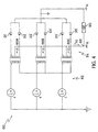
- FIG. 4 Another embodiment of a transformer/rectifier arrangement 80 is shown in Fig. 4.
- Input side 82 of arrangement 80 is shown identical to that of arrangement 50.
- the output side 84 of arrangement 80 includes secondary windings 86A, 86B, 86C which are also arranged in a full wave center-tap transformer output connection.
- the diodes D1'- D6' are connected in a reverse configuration such that common node 88 of the center-taps acts as the output which delivers current I DC2 to the load 90.
- the peak current through each diode is still 1 ⁇ 2I DC2' two diodes still conduct at one time, and each diode conducts for 120 electrical degrees.
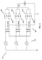
- FIG. 5 Still a further embodiment of a transformer/rectifier arrangement 100 is shown in Fig. 5.
- input side 102 of arrangement 100 is shown identical to that of arrangements 50 and 80.
- the output side 104 of arrangement 80 includes secondary windings 106A, 106B, 106C which are also arranged in a full-wave center-tap transformer output connection.
- twelve diodes are used by setting up diode pairs DP1 - DP6 in parallel.
- the peak current through each diode pair is one-half the dc output current I DC3 . Accordingly, the peak current through each individual diode will only be one-fourth the dc output current I DC3 .
- Two diode pairs will conduct at one time and each diode pair will be on for 120 electrical degrees. It is recognized that additional paralleling could be used, and that similar paralleling could be used in conjunction with arrangement 80 of Fig. 4.
- FIG. 6 shows a block diagram of an aircraft ground power unit (GPU) 110.
- the GPU 110 includes a source 112 of 3-phase ac power which, by way of example but not by way of limitation, could be a generator or a static converter.
- the 3-phase ac power may be on the order of 115 volts line-to-neutral, 200 volts line-to-line.
- A, B, and C phase outputs are fed to a contacter 114 which can be used to control delivery of the A, B, and C phase currents to the transformer/rectifier 50, 80, 100.
- the dc output of the transformer/rectifier can then be delivered to the load (aircraft power system).
- a second contacter 116 may be used to deliver the 3-phase ac power to the load as well. In operation the contacters may be actuated by switches, buttons or levers of the GPU 110 which allows the user to select between outputting dc or 3-phase ac.
Landscapes
- Engineering & Computer Science (AREA)
- Power Engineering (AREA)
- Rectifiers (AREA)
Abstract
Description

Claims (10)
- An aircraft ground power unit for providing dc power for aircraft, comprising:wherein the A-phase primary winding first side is operatively connected to receive A-phase power, wherein the B-phase primary winding first side is operatively connected to receive B-phase power, wherein the C-phase primary winding first side is operatively connected to receive C-phase; and,a transformer/rectifier arrangement for connection to a source of 3-phase ac power including A, B and C phases for converting the 3-phase ac power to dc power, including:an A-phase transformer formed by an A-phase magnetic member, an A-phase primary winding having first and second sides, and an A-phase secondary winding;a B-phase transformer formed by a B-phase magnetic member, a B-phase primary winding having first and second sides, and a B-phase secondary winding;a C-phase transformer formed by a C-phase magnetic member, a C-phase primary winding having first and second sides, and a C-phase secondary winding;
wherein the A-phase primary winding second side, B-phase primary winding second side and C-phase primary winding second side are connected together for delivering current traveling out of one of said second sides into at least one of said other second sides. - A unit according to claim 1 wherein the A-phase, B-phase, and C-phase secondary windings of the transformer/rectifier arrangement are arranged in a full wave center-tap transformer output connection which includes an output for delivering current to a load when connected thereto.
- A unit according to claim 2, wherein each secondary winding has a center-tap to ground, each secondary winding has first and second sides each connected to an anode side of a respective diode, and a cathode side of each diode connects to a common node which defines the output.
- A unit according to claim 1 or 2, wherein during operation a peak dc current through each diode of the full wave center-tap transformer output connection is V2 a load current delivered to the output or wherein during operation two diodes of the full wave center-tap transformer output connection conduct at any one time.
- A unit according to any one of the preceding claims including a source of 3-phase ac power including A, B and C phases and wherein the A-phase primary winding first side is operatively connected to receive A-phase power from said source, and wherein the B-phase primary winding first side is operatively connected to receive B-phase power from said source, wherein the C-phase primary winding first side is operatively connected to receive C-phase power from said source.
- A unit according to claim 5, wherein the first, second and third primary windings are connected to the source of 3-phase ac power through a contacter for controllably delivering the 3-phase power thereto.
- An aircraft ground power unit for selectively providing ac and dc power to an aircraft, comprising:a source of 3-phase power including A, B and C phases;a transformer/rectifier arrangement for converting 3-phase ac power to dc power, including:an A-phase transformer formed by an A-phase magnetic member, an A-phase primary winding having first and second sides, and an A-phase secondary winding;a B-phase transformer formed by a B-phase magnetic member, a B-phase primary winding having first and second sides, and a B-phase secondary winding;a C-phase transformer formed by a C-phase magnetic member, a C-phase primary winding having first and second sides, and a C-phase secondary winding;wherein the A-phase primary winding second side, B-phase primary winding second side and C-phase primary winding second side are connected together for delivering current traveling out of one of said second sides into at least one of said other second sides;a set of dc outputs for delivering dc power to the aircraft;a set of 3-phase outputs for delivering 3-phase ac power to the aircraft;at least one contacter connected between the 3-phase source and the transformer/rectifier arrangement for selectively connecting the transformer/rectifier arrangement to the source of 3-phase power such that when so connected the A-phase primary winding first side is connected to receive A-phase power, the B-phase primary winding first side is connected to receive B-phase power, and the C-phase primary winding first side is connected to receive C-phase power; andat least one contacter connected between the source of 3-phase power and the set of 3-phase outputs for selectively controlling delivery of 3-phase ac power thereto.
- An aircraft ground power unit for selectively providing ac and dc power to an aircraft, comprising:a source of 3-phase power;a transformer/rectifier arrangement, including:an A-phase transformer formed by an A-phase magnetic member, an A-phase primary winding, and an A-phase secondary winding;a B-phase transformer formed by a B-phase magnetic member, a B-phase primary winding, and a B-phase secondary winding;a C-phase transformer formed by a C-phase magnetic member, a C-phase primary winding, and a C-phase secondary winding;wherein the A-phase primary winding , B-phase primary winding, and C-phase primary winding are connected in a neutral free STAR (Y) configuration; andwherein the A-phase, B-phase, and C-phase secondary windings are arranged in a full wave center-tap transformer output connection which includes an output for delivering current to a load when connected thereto;a set of dc outputs for delivering dc power to the aircraft;a set of 3-phase outputs for delivering 3-phase ac power to the aircraft;at least one switching circuit for controlling delivery of 3-phase power from the source of 3-phase power to the transformer/rectifier arrangement and the set of 3-phase outputs.
- A unit according to any one of the preceding claims, wherein the output of the transformer/rectifier arrangement is rated to deliver at least 300 amps dc.
- A unit according to any one of the preceding claims, wherein the output of the transformer/rectifier arrangement is rated to deliver about 28 volts dc.
Applications Claiming Priority (4)
| Application Number | Priority Date | Filing Date | Title |
|---|---|---|---|
| US24250400P | 2000-10-23 | 2000-10-23 | |
| US242504P | 2000-10-23 | ||
| US715309 | 2000-11-17 | ||
| US09/715,309 US6320773B1 (en) | 2000-10-23 | 2000-11-17 | Transformer/rectifier for aircraft ground power unit |
Publications (2)
| Publication Number | Publication Date |
|---|---|
| EP1202443A2 true EP1202443A2 (en) | 2002-05-02 |
| EP1202443A3 EP1202443A3 (en) | 2002-11-06 |
Family
ID=26935138
Family Applications (1)
| Application Number | Title | Priority Date | Filing Date |
|---|---|---|---|
| EP01308681A Withdrawn EP1202443A3 (en) | 2000-10-23 | 2001-10-10 | Transformer/rectifier for aircraft ground power unit |
Country Status (3)
| Country | Link |
|---|---|
| US (1) | US6320773B1 (en) |
| EP (1) | EP1202443A3 (en) |
| CA (1) | CA2359717C (en) |
Families Citing this family (17)
| Publication number | Priority date | Publication date | Assignee | Title |
|---|---|---|---|---|
| US6424891B1 (en) * | 1999-03-31 | 2002-07-23 | The United States Of America As Represented By The Secretary Of The Air Force | Aircraft ground power unit |
| US7388334B2 (en) * | 2003-04-04 | 2008-06-17 | Purespectrum, Inc. | High frequency electronic ballast with sine wave oscillator |
| US8047555B2 (en) * | 2007-10-31 | 2011-11-01 | Illinois Tool Works Inc. | Airplane ground support equipment cart having extractable modules and a generator module that is seperable from power conversion and air conditioning modules |
| US8117864B2 (en) * | 2007-10-31 | 2012-02-21 | Illinois Tool Works Inc. | Compact, modularized air conditioning system that can be mounted upon an airplane ground support equipment cart |
| US8055388B2 (en) * | 2007-10-31 | 2011-11-08 | Illinois Tool Works Inc. | Maintenance and control system for ground support equipment |
| US8030801B2 (en) * | 2007-10-31 | 2011-10-04 | Illinois Tool Works Inc. | Multi-voltage power supply for a universal airplane ground support equipment cart |
| US20090107657A1 (en) * | 2007-10-31 | 2009-04-30 | Montminy Jeffrey E | Adjustable cooling system for airplane electronics |
| US8037714B2 (en) * | 2007-10-31 | 2011-10-18 | Illinois Tool Works Inc. | Adjustable air conditioning control system for a universal airplane ground support equipment cart |
| US20090108549A1 (en) * | 2007-10-31 | 2009-04-30 | Montminy Jeffrey E | Frame and panel system for constructing modules to be installed on an airplane ground support equipment cart |
| US20100090789A1 (en) * | 2008-10-14 | 2010-04-15 | Middle Atlantic Products, Inc. | Method, system and transformer for mitigating harmonics |
| US9413264B2 (en) * | 2009-12-07 | 2016-08-09 | Illinois Tool Works Inc. | Ground power unit for aircraft |
| TWI486753B (en) * | 2010-01-12 | 2015-06-01 | 緯創資通股份有限公司 | Power supply system and portable electronic device |
| US8339810B2 (en) * | 2010-03-12 | 2012-12-25 | Illinois Tool Works Inc. | Wide input voltage power supply |
| US20120013428A1 (en) * | 2010-07-16 | 2012-01-19 | Tony Hoevenaars | Step-down autotransformer for a power distribution system with non-linear loads |
| CN105099215A (en) * | 2014-05-21 | 2015-11-25 | 济南芯驰能源科技有限公司 | Aircraft ground miniaturization power supply suitable for multiple power supply modes |
| US10141829B2 (en) | 2016-06-29 | 2018-11-27 | John Bean Technologies Corporation | Multiple power topologies from single power generator |
| EP4014310A1 (en) * | 2019-08-15 | 2022-06-22 | EM-Energy Solutions AS | System and method for controlling a 3-phase transformer device |
Family Cites Families (17)
| Publication number | Priority date | Publication date | Assignee | Title |
|---|---|---|---|---|
| DE1763530C3 (en) | 1968-06-19 | 1980-09-11 | Danfoss As | Three phase inverter |
| US4068157A (en) * | 1974-11-29 | 1978-01-10 | Sola Basic Industries, Inc. | Regulated multiple transformer system |
| JPS5179247A (en) * | 1975-01-06 | 1976-07-10 | Hitachi Ltd | 3 soseigyohoshiki |
| JPS5364724A (en) | 1976-11-22 | 1978-06-09 | Nasuko Kk | Method of controlling thyristor avvdc converter |
| CA1110695A (en) | 1977-07-25 | 1981-10-13 | Martin H.F. Garnham | Rectifiers having compensating transformer unit |
| US4493016A (en) | 1982-10-07 | 1985-01-08 | Westinghouse Electric Corp. | Rectifier transformer |
| US4663702A (en) | 1984-10-12 | 1987-05-05 | Kabushiki Kaisha Toshiba | Power converter apparatus and control method thereof |
| US5050058A (en) | 1990-08-14 | 1991-09-17 | La Corporation De L'ecole Polytechnique | Family of power converters using rectifier transformers connected in series on the primary side |
| DE4033281A1 (en) * | 1990-10-19 | 1992-04-23 | Bruker Analytische Messtechnik | HIGH-PERFORMANCE POWER SUPPLY |
| US5267137A (en) * | 1990-10-19 | 1993-11-30 | Kohler, Schmid Partner | High-power power supply |
| JP2760666B2 (en) | 1991-03-15 | 1998-06-04 | 株式会社東芝 | Method and apparatus for controlling PWM converter |
| US5539632A (en) * | 1991-06-28 | 1996-07-23 | Marsh; John K. | Multi-phase and shifted phase power distribution systems |
| DE4241486A1 (en) | 1992-12-09 | 1994-06-16 | Antelec Eng Gmbh | Converter |
| JP3171488B2 (en) * | 1992-09-29 | 2001-05-28 | 株式会社東芝 | Transformer for cyclo converter |
| US5781428A (en) | 1997-03-03 | 1998-07-14 | Paice; Derek A. | Transformer for 12-pulse series connection of converters |
| JP2961659B1 (en) * | 1998-09-02 | 1999-10-12 | 株式会社京三製作所 | Three-phase rectifier |
| US6026006A (en) | 1998-09-21 | 2000-02-15 | Lucent Technologies Inc. | Integrated three-phase power converter and method of operation thereof |
-
2000
- 2000-11-17 US US09/715,309 patent/US6320773B1/en not_active Expired - Fee Related
-
2001
- 2001-10-10 EP EP01308681A patent/EP1202443A3/en not_active Withdrawn
- 2001-10-17 CA CA002359717A patent/CA2359717C/en not_active Expired - Fee Related
Also Published As
| Publication number | Publication date |
|---|---|
| EP1202443A3 (en) | 2002-11-06 |
| CA2359717C (en) | 2005-05-17 |
| US6320773B1 (en) | 2001-11-20 |
| CA2359717A1 (en) | 2002-04-23 |
Similar Documents
| Publication | Publication Date | Title |
|---|---|---|
| CA2359717C (en) | Transformer/rectifier for aircraft ground power unit | |
| US8737097B1 (en) | Electronically isolated method for an auto transformer 12-pulse rectification scheme suitable for use with variable frequency drives | |
| US5148357A (en) | Auto-connected hexagon transformer for a 12-pulse converter | |
| EP2320550B1 (en) | Power transformer and power converter incorporating same | |
| US20020034083A1 (en) | Zero voltage switching DC-DC converter | |
| JP2991181B2 (en) | Switching power supply | |
| US6831442B2 (en) | Utilizing zero-sequence switchings for reversible converters | |
| US12451815B2 (en) | Voltage transformer | |
| EP4147340B1 (en) | Electrical power converter | |
| JPWO2007069556A1 (en) | High frequency modulation / demodulation multiphase rectifier | |
| JP2001047894A (en) | AC feeding device and control method of AC feeding device | |
| EP2221953B1 (en) | Power supply device | |
| JP2010017047A (en) | Three-phase power factor improving circuit | |
| EP1906517A2 (en) | Systems and methods for balancing of DC link in three level PWM power conversion equipment | |
| IE80543B1 (en) | Optimized 18-pulse type ac/dc or dc/ac converter system | |
| JP2010041744A (en) | Uninterruptible power supply device, and method of manufacturing the same | |
| CN112820524A (en) | Multi-phase transformer and rectifier system | |
| JP4513185B2 (en) | Three-phase half-voltage output type rectifier | |
| JP2011239487A (en) | Synchronous generator | |
| RU2362261C1 (en) | Phase-converting device | |
| US6208230B1 (en) | Transformer for cycloconverter | |
| KR102482962B1 (en) | PSFB(Phase-Shift Full-Bridge) converter | |
| JP7515824B2 (en) | Power Conversion Equipment | |
| US6194795B1 (en) | Transformer configuration | |
| US20130301329A1 (en) | Electrical circuit, in particular used for generating electrical power |
Legal Events
| Date | Code | Title | Description |
|---|---|---|---|
| PUAI | Public reference made under article 153(3) epc to a published international application that has entered the european phase |
Free format text: ORIGINAL CODE: 0009012 |
|
| AK | Designated contracting states |
Kind code of ref document: A2 Designated state(s): AT BE CH CY DE DK ES FI FR GB GR IE IT LI LU MC NL PT SE TR |
|
| AX | Request for extension of the european patent |
Free format text: AL;LT;LV;MK;RO;SI |
|
| PUAL | Search report despatched |
Free format text: ORIGINAL CODE: 0009013 |
|
| AK | Designated contracting states |
Kind code of ref document: A3 Designated state(s): AT BE CH CY DE DK ES FI FR GB GR IE IT LI LU MC NL PT SE TR |
|
| AX | Request for extension of the european patent |
Free format text: AL;LT;LV;MK;RO;SI |
|
| RIC1 | Information provided on ipc code assigned before grant |
Free format text: 7H 02M 7/10 A, 7H 02M 7/145 B, 7H 02M 7/02 B, 7H 02M 7/17 B, 7H 02M 5/27 B |
|
| 17P | Request for examination filed |
Effective date: 20030422 |
|
| AKX | Designation fees paid |
Designated state(s): DE FR GB |
|
| 17Q | First examination report despatched |
Effective date: 20030827 |
|
| GRAP | Despatch of communication of intention to grant a patent |
Free format text: ORIGINAL CODE: EPIDOSNIGR1 |
|
| STAA | Information on the status of an ep patent application or granted ep patent |
Free format text: STATUS: THE APPLICATION IS DEEMED TO BE WITHDRAWN |
|
| 18D | Application deemed to be withdrawn |
Effective date: 20040806 |