EP1202423A2 - Actuator drive circuit - Google Patents
Actuator drive circuit Download PDFInfo
- Publication number
- EP1202423A2 EP1202423A2 EP01309080A EP01309080A EP1202423A2 EP 1202423 A2 EP1202423 A2 EP 1202423A2 EP 01309080 A EP01309080 A EP 01309080A EP 01309080 A EP01309080 A EP 01309080A EP 1202423 A2 EP1202423 A2 EP 1202423A2
- Authority
- EP
- European Patent Office
- Prior art keywords
- actuator
- drive circuit
- current
- actuator drive
- limiting device
- Prior art date
- Legal status (The legal status is an assumption and is not a legal conclusion. Google has not performed a legal analysis and makes no representation as to the accuracy of the status listed.)
- Withdrawn
Links
Images
Classifications
-
- G—PHYSICS
- G11—INFORMATION STORAGE
- G11B—INFORMATION STORAGE BASED ON RELATIVE MOVEMENT BETWEEN RECORD CARRIER AND TRANSDUCER
- G11B7/00—Recording or reproducing by optical means, e.g. recording using a thermal beam of optical radiation by modifying optical properties or the physical structure, reproducing using an optical beam at lower power by sensing optical properties; Record carriers therefor
- G11B7/08—Disposition or mounting of heads or light sources relatively to record carriers
- G11B7/09—Disposition or mounting of heads or light sources relatively to record carriers with provision for moving the light beam or focus plane for the purpose of maintaining alignment of the light beam relative to the record carrier during transducing operation, e.g. to compensate for surface irregularities of the latter or for track following
- G11B7/0925—Electromechanical actuators for lens positioning
-
- G—PHYSICS
- G11—INFORMATION STORAGE
- G11B—INFORMATION STORAGE BASED ON RELATIVE MOVEMENT BETWEEN RECORD CARRIER AND TRANSDUCER
- G11B21/00—Head arrangements not specific to the method of recording or reproducing
- G11B21/02—Driving or moving of heads
-
- H—ELECTRICITY
- H02—GENERATION; CONVERSION OR DISTRIBUTION OF ELECTRIC POWER
- H02H—EMERGENCY PROTECTIVE CIRCUIT ARRANGEMENTS
- H02H9/00—Emergency protective circuit arrangements for limiting excess current or voltage without disconnection
- H02H9/02—Emergency protective circuit arrangements for limiting excess current or voltage without disconnection responsive to excess current
- H02H9/026—Current limitation using PTC resistors, i.e. resistors with a large positive temperature coefficient
-
- G—PHYSICS
- G11—INFORMATION STORAGE
- G11B—INFORMATION STORAGE BASED ON RELATIVE MOVEMENT BETWEEN RECORD CARRIER AND TRANSDUCER
- G11B7/00—Recording or reproducing by optical means, e.g. recording using a thermal beam of optical radiation by modifying optical properties or the physical structure, reproducing using an optical beam at lower power by sensing optical properties; Record carriers therefor
- G11B7/08—Disposition or mounting of heads or light sources relatively to record carriers
- G11B7/085—Disposition or mounting of heads or light sources relatively to record carriers with provision for moving the light beam into, or out of, its operative position or across tracks, otherwise than during the transducing operation, e.g. for adjustment or preliminary positioning or track change or selection
Definitions
- This invention relates to a circuit protection device for an actuator drive circuit.
- the invention relates to a current limiting device which allows large amounts of current to flow for short period of time and acts as a circuit overload protector.
- Present circuit overload protectors set a low limit on the maximum current fed to an actuator. However, this limits the acceleration achievable by the actuator, thus making it slow to function. Examples of such actuators are voice coil motors, linear or rotary motors or any coil of wire in a magnetic field.
- One purpose of the present invention is to provide a current limiting device to the actuator drive circuit which allows large amounts of current to flow for a short period time, but before the actuator can overheat.
- the invention comprises an actuator drive circuit comprising:
- the invention comprises a CD or DVD player including an electro dynamic actuator comprising wire coil means which is driven by an actuator drive circuit in accordance with the first aspect of the invention.
- an actuator drive circuit employs a current limiting device with a strong positive temperature coefficient of resistance.
- the current limiting device allows large amounts of current to flow for a short period of time, prior to the actuator overheating, by having the device's resistance rise and thus lowering the current flow.
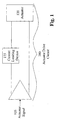
- Figure 1 is a schematic illustration of an actuator drive circuit 100 for a position tracking servo mechanism
- the actuator drive circuit 100 includes an actuator control signal 105, an amplifier 110, a current limiting device 115 and an actuator 120.
- the actuator control signal 105 is sent through the amplifier 110 to the actuator 120.
- the current limiting device 115 is electrically connected in series with the actuator 120.
- the current limiting device 115 is an incandescent lamp.
- a user can choose the characteristics of the filament in the lamp such that larger short duration currents that are needed to move the actuator 120 pass through the light bulb.
- a typical incandescent bulb filament has a rather large change in resistance between a cold state and the illuminated state. Although the filament warms up a small amount during the flow of the current, it passes essentially unimpeded by the resistence of the filament. However, if there was a problem or if the demands were high for some reason due to, for example, the motion of the actuator device, and the high current persisted too long, the filament of the current limiting device 115 would heat up more rapidly than the actuator's 120 coil that is being driven by this current. The lamp will absorb the energy and its resistence would increase and thus prevent the high current from existing for a longer period of time than would be safe for the actuator 120.
- the current were to persist for an extended period of time, it overheats the actuator 120 and burns up the coil of wire.
- the current limiting device 115 or any other device with a strong positive temperature coefficient of resistence in series with the actuator 120, a larger amount of current flow is able to be used for a short period of time.
- CD and DVD players contain electro dynamic actuators comprised of little coils of wire and magnets that move a lens such that a laser spot is tracked with extreme accuracy on the data to be read or written.
- electro dynamic actuators comprised of little coils of wire and magnets that move a lens such that a laser spot is tracked with extreme accuracy on the data to be read or written.
- the actuator drive circuit 100 has to move very quickly.
- a short pulse of current is sent through the coil of wire that causes the necessary motion.
- the current limiting device 115 limits the amount of current sent to the actuator 120 to keep the coils in the actuator 120 from burning up. This is accomplished by the current limiting device's 115 resistance rising and thus lowering the current flow to the actuator 120.
Landscapes
- Engineering & Computer Science (AREA)
- Power Engineering (AREA)
- Control Of Electric Motors In General (AREA)
- Emergency Protection Circuit Devices (AREA)
- Control Of Linear Motors (AREA)
- Optical Recording Or Reproduction (AREA)
Abstract
Description
Claims (7)
- An actuator drive circuit (100) comprising:wherein during current flow, resistence of the current limiting device rises and current flow to the actuator is lowered.an actuator (120);at least one current limiting device (115); anda signal (105) to allow current flow through the actuator drive circuit;
- The actuator drive circuit of claim 1 further comprising:an amplifier.
- The actuator drive circuit of claim 1 wherein the current limiting device (115) is electrically connected in series with the actuator (120).
- The actuator drive circuit of claim 1 wherein the current limiting device (115) has a strong positive temperature coefficient of resistance.
- The actuator drive circuit of claim 1 wherein there is a large current flow for a short duration of time.
- The actuator drive circuit of claim 4 wherein the current limiting device (115) is a lamp.
- A CD or DVD player including an electro dynamic actuator comprising wire coil means which is driven by an actuator drive circuit (100) in accordance with any preceding claim.
Applications Claiming Priority (2)
| Application Number | Priority Date | Filing Date | Title |
|---|---|---|---|
| US69956300A | 2000-10-31 | 2000-10-31 | |
| US699563 | 2000-10-31 |
Publications (2)
| Publication Number | Publication Date |
|---|---|
| EP1202423A2 true EP1202423A2 (en) | 2002-05-02 |
| EP1202423A3 EP1202423A3 (en) | 2003-03-26 |
Family
ID=24809882
Family Applications (1)
| Application Number | Title | Priority Date | Filing Date |
|---|---|---|---|
| EP01309080A Withdrawn EP1202423A3 (en) | 2000-10-31 | 2001-10-25 | Actuator drive circuit |
Country Status (4)
| Country | Link |
|---|---|
| EP (1) | EP1202423A3 (en) |
| JP (1) | JP2002218790A (en) |
| KR (1) | KR100786457B1 (en) |
| CN (1) | CN1351400A (en) |
Cited By (2)
| Publication number | Priority date | Publication date | Assignee | Title |
|---|---|---|---|---|
| WO2004059649A1 (en) * | 2002-12-30 | 2004-07-15 | Koninklijke Philips Electronics N.V. | Method for driving an actuator, actuator drive, and apparatus comprising an actuator |
| DE102006045043A1 (en) * | 2006-09-25 | 2008-04-03 | Siemens Ag | Shape memory unit for use in switching device and household appliance, has glow lamp switched electrically parallel to memory unit, and filament provided so that current intensity of pulse is decreased with limited duration in memory unit |
Family Cites Families (4)
| Publication number | Priority date | Publication date | Assignee | Title |
|---|---|---|---|---|
| JP2731673B2 (en) * | 1992-07-03 | 1998-03-25 | 富士通株式会社 | Disk unit |
| US5471035A (en) * | 1993-10-22 | 1995-11-28 | Eaton Corporation | Sandwich construction for current limiting positive temperature coefficient protective device |
| JPH11144362A (en) * | 1997-11-07 | 1999-05-28 | Teac Corp | Information recording / reproducing device |
| JP2000251272A (en) * | 1999-03-03 | 2000-09-14 | Matsushita Electric Ind Co Ltd | Optical disk drive |
-
2001
- 2001-08-30 CN CN01125136A patent/CN1351400A/en active Pending
- 2001-10-22 JP JP2001323270A patent/JP2002218790A/en active Pending
- 2001-10-25 EP EP01309080A patent/EP1202423A3/en not_active Withdrawn
- 2001-10-30 KR KR1020010067002A patent/KR100786457B1/en not_active Expired - Fee Related
Cited By (3)
| Publication number | Priority date | Publication date | Assignee | Title |
|---|---|---|---|---|
| WO2004059649A1 (en) * | 2002-12-30 | 2004-07-15 | Koninklijke Philips Electronics N.V. | Method for driving an actuator, actuator drive, and apparatus comprising an actuator |
| US7782720B2 (en) | 2002-12-30 | 2010-08-24 | Koninklijke Philips Electronics N.V. | Method for driving an actuator, actuator drive, and apparatus comprising an actuator |
| DE102006045043A1 (en) * | 2006-09-25 | 2008-04-03 | Siemens Ag | Shape memory unit for use in switching device and household appliance, has glow lamp switched electrically parallel to memory unit, and filament provided so that current intensity of pulse is decreased with limited duration in memory unit |
Also Published As
| Publication number | Publication date |
|---|---|
| KR100786457B1 (en) | 2007-12-17 |
| KR20020033558A (en) | 2002-05-07 |
| CN1351400A (en) | 2002-05-29 |
| JP2002218790A (en) | 2002-08-02 |
| EP1202423A3 (en) | 2003-03-26 |
Similar Documents
| Publication | Publication Date | Title |
|---|---|---|
| US20080002538A1 (en) | System for Controlling the Temperature in Components | |
| EP1202423A2 (en) | Actuator drive circuit | |
| CN103904934A (en) | Micron order converse magnetostriction driver and use method thereof | |
| KR20010094008A (en) | Optical pick up actuator | |
| TW200415632A (en) | Optical actuator | |
| US5383081A (en) | Live insertion circuit | |
| WO2001073927A2 (en) | Linear voice coil actuator with compensating coils | |
| JP2011193158A (en) | Sensor output ic and sensor device | |
| JPS5910789A (en) | Actuator which comprises shape memorizy alloy | |
| WO2019088924A1 (en) | Linear motor with heat dissipating capabilities and heat reducing considerations | |
| JP3850925B2 (en) | Integrated circuit compensation apparatus and method | |
| JP3287261B2 (en) | Optical pickup device | |
| CN2323512Y (en) | Brushless DC motor drive circuit protection device | |
| JP2001034962A (en) | Optical disk drive | |
| US6501726B1 (en) | Magnetic coil actuator | |
| KR870000799B1 (en) | Mirror apparatus | |
| CN119993677A (en) | Solenoid protection device, solenoid assembly, electronic device, and control method | |
| JPH038129A (en) | Objective lens driving device | |
| JP2593913B2 (en) | Non-contact relay device | |
| JP4377431B2 (en) | Light source protection device and disk device | |
| JP4564944B2 (en) | Optical pickup | |
| KR20040071464A (en) | Apparatus for preventing excess current in optical pick-up | |
| JPH042419Y2 (en) | ||
| JPH02103738A (en) | optical pickup | |
| JPS62117014A (en) | Actuator |
Legal Events
| Date | Code | Title | Description |
|---|---|---|---|
| PUAI | Public reference made under article 153(3) epc to a published international application that has entered the european phase |
Free format text: ORIGINAL CODE: 0009012 |
|
| AK | Designated contracting states |
Kind code of ref document: A2 Designated state(s): AT BE CH CY DE DK ES FI FR GB GR IE IT LI LU MC NL PT SE TR |
|
| AX | Request for extension of the european patent |
Free format text: AL;LT;LV;MK;RO;SI |
|
| PUAL | Search report despatched |
Free format text: ORIGINAL CODE: 0009013 |
|
| AK | Designated contracting states |
Kind code of ref document: A3 Designated state(s): AT BE CH CY DE DK ES FI FR GB GR IE IT LI LU MC NL PT SE TR Designated state(s): AT BE CH CY DE DK ES FI FR GB GR IE IT LI LU MC NL PT SE TR |
|
| AX | Request for extension of the european patent |
Extension state: AL LT LV MK RO SI |
|
| 17P | Request for examination filed |
Effective date: 20030926 |
|
| AKX | Designation fees paid |
Designated state(s): DE GB NL |
|
| 17Q | First examination report despatched |
Effective date: 20070612 |
|
| STAA | Information on the status of an ep patent application or granted ep patent |
Free format text: STATUS: THE APPLICATION IS DEEMED TO BE WITHDRAWN |
|
| 18D | Application deemed to be withdrawn |
Effective date: 20090409 |