EP1202420A1 - Insulating container for a branch junction for electrical cables, and method of making a branch junction - Google Patents
Insulating container for a branch junction for electrical cables, and method of making a branch junction Download PDFInfo
- Publication number
- EP1202420A1 EP1202420A1 EP01402745A EP01402745A EP1202420A1 EP 1202420 A1 EP1202420 A1 EP 1202420A1 EP 01402745 A EP01402745 A EP 01402745A EP 01402745 A EP01402745 A EP 01402745A EP 1202420 A1 EP1202420 A1 EP 1202420A1
- Authority
- EP
- European Patent Office
- Prior art keywords
- insulating container
- branch
- phase conductor
- container
- contact
- Prior art date
- Legal status (The legal status is an assumption and is not a legal conclusion. Google has not performed a legal analysis and makes no representation as to the accuracy of the status listed.)
- Granted
Links
- 238000004519 manufacturing process Methods 0.000 title claims description 5
- 239000004020 conductor Substances 0.000 claims abstract description 27
- 238000003780 insertion Methods 0.000 claims abstract description 6
- 230000037431 insertion Effects 0.000 claims abstract description 6
- 238000000034 method Methods 0.000 claims description 5
- 238000003825 pressing Methods 0.000 claims description 4
- 239000013013 elastic material Substances 0.000 claims description 2
- 230000000087 stabilizing effect Effects 0.000 claims description 2
- 230000006978 adaptation Effects 0.000 description 2
- 210000003141 lower extremity Anatomy 0.000 description 2
- 239000002184 metal Substances 0.000 description 2
- 238000012986 modification Methods 0.000 description 2
- 230000004048 modification Effects 0.000 description 2
- 239000011347 resin Substances 0.000 description 2
- 229920005989 resin Polymers 0.000 description 2
- 238000006467 substitution reaction Methods 0.000 description 2
- 239000000428 dust Substances 0.000 description 1
- 238000009413 insulation Methods 0.000 description 1
- 239000000463 material Substances 0.000 description 1
- 239000007769 metal material Substances 0.000 description 1
- 229920001296 polysiloxane Polymers 0.000 description 1
- 238000010079 rubber tapping Methods 0.000 description 1
- 239000000565 sealant Substances 0.000 description 1
Images


Classifications
-
- H—ELECTRICITY
- H01—ELECTRIC ELEMENTS
- H01R—ELECTRICALLY-CONDUCTIVE CONNECTIONS; STRUCTURAL ASSOCIATIONS OF A PLURALITY OF MUTUALLY-INSULATED ELECTRICAL CONNECTING ELEMENTS; COUPLING DEVICES; CURRENT COLLECTORS
- H01R9/00—Structural associations of a plurality of mutually-insulated electrical connecting elements, e.g. terminal strips or terminal blocks; Terminals or binding posts mounted upon a base or in a case; Bases therefor
- H01R9/03—Connectors arranged to contact a plurality of the conductors of a multiconductor cable, e.g. tapping connections
- H01R9/031—Connectors arranged to contact a plurality of the conductors of a multiconductor cable, e.g. tapping connections for multiphase cables, e.g. with contact members penetrating insulation of a plurality of conductors
-
- H—ELECTRICITY
- H01—ELECTRIC ELEMENTS
- H01R—ELECTRICALLY-CONDUCTIVE CONNECTIONS; STRUCTURAL ASSOCIATIONS OF A PLURALITY OF MUTUALLY-INSULATED ELECTRICAL CONNECTING ELEMENTS; COUPLING DEVICES; CURRENT COLLECTORS
- H01R4/00—Electrically-conductive connections between two or more conductive members in direct contact, i.e. touching one another; Means for effecting or maintaining such contact; Electrically-conductive connections having two or more spaced connecting locations for conductors and using contact members penetrating insulation
- H01R4/24—Connections using contact members penetrating or cutting insulation or cable strands
- H01R4/2404—Connections using contact members penetrating or cutting insulation or cable strands the contact members having teeth, prongs, pins or needles penetrating the insulation
- H01R4/2407—Connections using contact members penetrating or cutting insulation or cable strands the contact members having teeth, prongs, pins or needles penetrating the insulation having saw-tooth projections
Definitions
- the present invention relates to electrical cables and particularly to branch junctions for electrical cables. Still more particularly it relates to a special insulating container used for making branch junctions for electrical cables.
- phase conductors of a main cable there are many cases in which it is necessary to connect the phase conductors of a main cable with the phase conductors of a branch cable.
- a typical case is when it is necessary to carry electrical power to a building (or group of buildings) by tapping it off from a main cable.
- Another problem with this known solution is the impossibility of checking the junction for efficiency once the insulating resin and/or tape has been applied. Indeed, if there is partial or total inefficiency of the junction the only option is to cut the length of main cable where the junction was made and make a new junction with a different device.
- the main object of the present invention is to provide an insulating container for making a branch junction for electrical cables that is practical and safe, both for an operator preparing the junction by hand and for the environment.
- Another object of the present invention is to provide an insulating container for making a branch junction for electrical cables that will enable such junctions to be made without interrupting the flow of electrical power in the main cable.
- an insulating container for a branch junction for electrical cables characterized in that it comprises:
- the present invention also proposes a method of making a branch junction between at least one phase conductor of a main electrical cable and at least one corresponding branch, the method being characterized in that it comprises the following steps:
- the container 10 of the invention comprises a longitudinally elongate body defining a cavity 12 that is essentially circular or in the shape of a tunnel, that is closed above by a curved vault-like surface.
- the elongate body preferably comprises two lower extremities or stabilizing edges 18 which may be of different shapes, such as for example the essentially circular shape seen in Fig. 5 or the straight shape seen in Figs. 1 and 2.
- the container of the invention is preferably made of a resilient, elastic material impervious to moisture, such as rubber. With this material the outer lower surface of the elongate body can adapt to the curvature of the phase conductors of the main cable, as will become clear in the course of the description.
- the elongate body of the container 10 of the invention has a first end, or end of insertion of the branch, that is open; the other end 22 (second end) is however closed. As shown in Fig. 3, at the closed end 22 both the inside cross section of the elongate body and the outside cross section become smaller.
- the outside cross section of the end 22 is preferably essentially circular and does not have the lower extremities 18.
- the container 10 of the invention also includes means 24 for making the electrical contact between a branch 36 and a phase conductor 32 of a main cable 30.
- the means 24 of electrical contact comprise a contact surface 14 and a pair of toothed plates 16 with a plurality of teeth 16'.
- the contact means 24 are preferably made from a single long metal plate. Before using the contact means 24 in the container 10, the toothed plates are bent through 90° with respect to the contact surface 14.
- the contact surface need not be continuous but could also comprise only surface portions (as in Fig. 4) in such a way as to connect the toothed plates 16 together. This solution has a number of advantages such as the use of less metallic material and the greater lightness and flexibility of the assembled container 10.
- the contact means 24 are first bent into an upside-down U, inserted into the cavity 12 and pressed down so that the teeth 16' penetrate through the bottom of the elongate body and protrude down to a certain length.
- at least one pair of teeth (16'a) can simply be bent around to secure it much like a staple.
- Preferably two (16'a, 16'b) or three pairs of teeth are bent around.
- a suitable length of sheath 34 is first removed from the main cable 30. This exposes the phase conductors 32 of the main cable 30.
- a completely assembled container 10 (with toothed plates inserted and protruding) is prepared.
- One end (with no insulating sheath) of each branch 36 is inserted into the cavity 12 of a corresponding container 10 as far as the closed end 22.
- the container 10 In order to establish the contact between the phase conductor 32 of the main cable 30 and the branch 36, the container 10 is simply pushed toward the phase conductor 32 so that the metal teeth 16 penetrate the sheath of the phase conductor 32 and come into contact with this phase conductor.
- the pressure can be applied by hand or by using a throttling strap or sleeve placed around the junction. In this way it is possible to make simultaneous contact between more than one branch and more than one corresponding phase conductor of the main cable.
- a sealant (such as silicone) may conveniently be used to prevent the ingress of dust and/or moisture through the holes made by the teeth 16.
- clasps For secure attachment of the containers to the main cable, clasps should preferably be used. These clasps (not illustrated because not the subject of the present invention) attach to the main cable and enable the branch cable to be clasped at two points to keep it parallel to the main cable.
- the terminal end 22 of the elongate body of the container 10 which is of a slightly larger circular cross section to that of the branch is ideal for fitting the abovementioned clasps.
Landscapes
- Cable Accessories (AREA)
- Insulating Bodies (AREA)
- Connections Effected By Soldering, Adhesion, Or Permanent Deformation (AREA)
Abstract
- a longitudinal cavity (12),
- an open first end for insertion of a branch
Description
- The present invention relates to electrical cables and particularly to branch junctions for electrical cables. Still more particularly it relates to a special insulating container used for making branch junctions for electrical cables.
- As is known, there are many cases in which it is necessary to connect the phase conductors of a main cable with the phase conductors of a branch cable. A typical case is when it is necessary to carry electrical power to a building (or group of buildings) by tapping it off from a main cable.
- Currently known solutions for making such branch junctions are complicated, dangerous, lengthy, inconvenient and unsafe from the point of view of protecting the environment. In practice it is necessary to interrupt the flow of electrical power in the main cable, remove the outer insulating sheath and manually strip a certain length of the cables (or phase conductors) from which the branches are to be taken. The stripped lengths are connected to the respective branches using clamp-type devices. The insulation of the main cable is renewed with insulating resin and/or tapes at the point where the insulating sheath has been removed.
- Another problem with this known solution is the impossibility of checking the junction for efficiency once the insulating resin and/or tape has been applied. Indeed, if there is partial or total inefficiency of the junction the only option is to cut the length of main cable where the junction was made and make a new junction with a different device.
- In light of the problems of the prior art, the main object of the present invention is to provide an insulating container for making a branch junction for electrical cables that is practical and safe, both for an operator preparing the junction by hand and for the environment.
- Another object of the present invention is to provide an insulating container for making a branch junction for electrical cables that will enable such junctions to be made without interrupting the flow of electrical power in the main cable.
- It is another object of the present invention to indicate a method of making a branch junction for electrical cables that is practical and safe, both for an operator preparing the junction by hand and for the environment.
- It is another object of the present invention to indicate a method for making a branch junction for electrical cables without interrupting the flow of electrical power in the main cable.
- These and other objects are achieved by means of an insulating container for a branch junction for electrical cables, characterized in that it comprises:
- ?? a longitudinally elongate body comprising:
- a longitudinal cavity,
- an open first end for insertion of a branch
- ?? means for the electrical contact between said longitudinal cavity and one phase conductor of a main electrical cable, said contact means comprising pressure members for coming into electrical contact with the transmissive part of said phase conductor.
-
- The present invention also proposes a method of making a branch junction between at least one phase conductor of a main electrical cable and at least one corresponding branch, the method being characterized in that it comprises the following steps:
- ?? providing at least one corresponding insulating container which in turn
comprises:
- a longitudinally elongate body comprising a longitudinal cavity and an open first end for insertion of a branch
- means for the electrical contact between said longitudinal cavity and the phase conductor, said contact means comprising pressure members for coming into electrical contact with the transmissive part of said phase conductor,
- ?? inserting one end of the branch into the longitudinal cavity
- ?? pressing the insulating container with the inserted branch onto the corresponding phase conductor of the main cable.
-
- There now follows a detailed description of the invention, given purely by way of non-limiting example, which should be read with reference to the accompanying sheets of illustrative drawings, in which:
- ?? Fig. 1 shows an end view of a first embodiment of the insulating container according to the present invention;
- ?? Fig. 2 is similar to Fig. 1 but shows a branch cable inserted into the insulating container;
- ?? Fig. 3 is a view in longitudinal section through the container seen in Fig. 1;
- ?? Fig. 4 shows the contact means before they are bent into a "U"; and
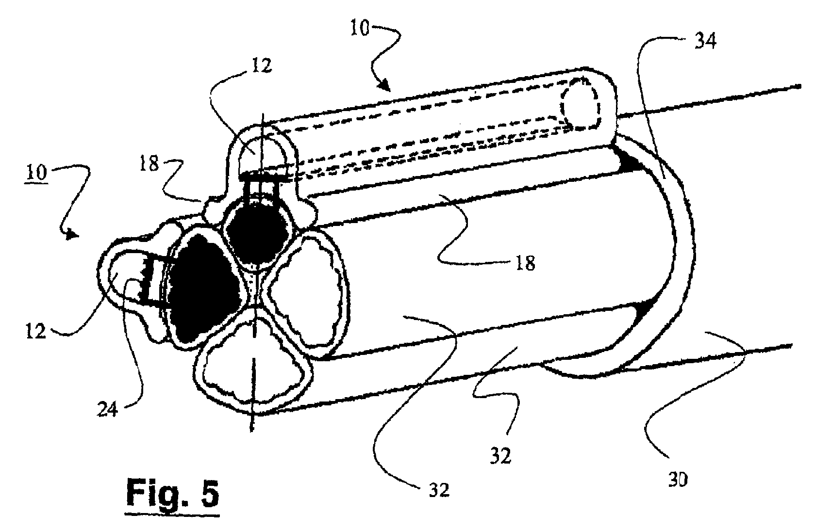
- ?? Fig. 5 shows a second embodiment of the container of the invention in a fitted configuration.
-
- With reference to the various figures, the
container 10 of the invention comprises a longitudinally elongate body defining acavity 12 that is essentially circular or in the shape of a tunnel, that is closed above by a curved vault-like surface. The elongate body preferably comprises two lower extremities or stabilizingedges 18 which may be of different shapes, such as for example the essentially circular shape seen in Fig. 5 or the straight shape seen in Figs. 1 and 2. The container of the invention is preferably made of a resilient, elastic material impervious to moisture, such as rubber. With this material the outer lower surface of the elongate body can adapt to the curvature of the phase conductors of the main cable, as will become clear in the course of the description. - The elongate body of the
container 10 of the invention has a first end, or end of insertion of the branch, that is open; the other end 22 (second end) is however closed. As shown in Fig. 3, at the closedend 22 both the inside cross section of the elongate body and the outside cross section become smaller. The outside cross section of theend 22 is preferably essentially circular and does not have thelower extremities 18. - The
container 10 of the invention also includesmeans 24 for making the electrical contact between abranch 36 and aphase conductor 32 of amain cable 30. In the preferred embodiment illustrated, themeans 24 of electrical contact comprise acontact surface 14 and a pair oftoothed plates 16 with a plurality of teeth 16'. The contact means 24 are preferably made from a single long metal plate. Before using the contact means 24 in thecontainer 10, the toothed plates are bent through 90° with respect to thecontact surface 14. The contact surface need not be continuous but could also comprise only surface portions (as in Fig. 4) in such a way as to connect thetoothed plates 16 together. This solution has a number of advantages such as the use of less metallic material and the greater lightness and flexibility of the assembledcontainer 10. - To assemble the contact means 24 with the elongate body, the contact means are first bent into an upside-down U, inserted into the
cavity 12 and pressed down so that the teeth 16' penetrate through the bottom of the elongate body and protrude down to a certain length. There are preferably holes (not shown) for this purpose in the bottom of the elongate body in which to insert the teeth 16'. In order to attach the contact means 24 securely to the elongate body, at least one pair of teeth (16'a) can simply be bent around to secure it much like a staple. Preferably two (16'a, 16'b) or three pairs of teeth are bent around. - With reference to Figs. 2 and 5 the use of the
container 10 of the invention will now be described, i.e. the method of making a branch junction for electrical cables. A suitable length ofsheath 34 is first removed from themain cable 30. This exposes thephase conductors 32 of themain cable 30. For eachphase conductor 32 of themain cable 30 from which a branch is required, a completely assembled container 10 (with toothed plates inserted and protruding) is prepared. One end (with no insulating sheath) of eachbranch 36 is inserted into thecavity 12 of acorresponding container 10 as far as the closedend 22. - In order to establish the contact between the
phase conductor 32 of themain cable 30 and thebranch 36, thecontainer 10 is simply pushed toward thephase conductor 32 so that themetal teeth 16 penetrate the sheath of thephase conductor 32 and come into contact with this phase conductor. The pressure can be applied by hand or by using a throttling strap or sleeve placed around the junction. In this way it is possible to make simultaneous contact between more than one branch and more than one corresponding phase conductor of the main cable. - A sealant (such as silicone) may conveniently be used to prevent the ingress of dust and/or moisture through the holes made by the
teeth 16. - For secure attachment of the containers to the main cable, clasps should preferably be used. These clasps (not illustrated because not the subject of the present invention) attach to the main cable and enable the branch cable to be clasped at two points to keep it parallel to the main cable. The
terminal end 22 of the elongate body of thecontainer 10 which is of a slightly larger circular cross section to that of the branch is ideal for fitting the abovementioned clasps. - In light of the above detailed description and accompanying drawings, the advantages obtained by the present invention in terms of practicality, convenience of use, safety and low cost will be obvious.
- It will be obvious that, in light of the above description, those skilled in the art will realize that numerous variants, modifications, adaptations and substitutions of parts with other functionally equivalent parts are possible. All these variants, modifications, adaptations and substitutions are however to be considered as coming within the scope of protection defined solely by the accompanying claims.
Claims (13)
- Insulating container (10) for a branch junction for electrical cables,
characterized in that it comprises:?? a longitudinally elongate body comprising:a longitudinal cavity (12),an open first end for insertion of a branch?? means (24) for the electrical contact between said longitudinal cavity (12) and one phase conductor (32) of a main electrical cable (30), said contact means (24) comprising pressure members (16) for coming into electrical contact with the transmissive part of said phase conductor (32). - Insulating container (10) according to claim 1, characterized in that said pressure members (16) comprise teeth (16').
- Insulating container (10) according to claim 2, characterized in that said teeth (16') comprise a first series of in-line teeth (16') and a second series of in-line teeth (16'), the two series of teeth being parallel.
- Insulating container (10) according to anyone of claims 1 to 3, characterized in that said contact means (24) comprise an internal contact surface (14).
- Insulating container (10) according to anyone of claims 1 to 4, characterized in that it comprises means (16'a, 16'b) for fixing said contact means (24) to the elongate body of the container (10).
- Insulating container (10) according to claim 5, characterized in that the means (16'a, 16'b) for fixing said contact means (24) to the elongate body of the container (10) comprise at least one pair of teeth (16'a, 16'b) that can be bent over each other like a staple.
- Insulating container (10) according to anyone of claims 1 to 6, characterized in that it comprises a second closed end (22) at the opposite end from the open end.
- Insulating container (10) according to claim 7, characterized in that said closed end (22) has a smaller external cross section than the elongate body.
- Insulating container (10) according to anyone of claims 1 to 8, characterized in that it comprises two stabilizing projecting edges (18).
- Insulating container (10) according to anyone of claims 1 to 9, characterized in that it comprises a resilient elastic material such as rubber.
- Method of making a branch junction between at least one phase conductor (32) of a main electrical cable (30) and at least one corresponding branch (36), the method being characterized in that it comprises the following steps:?? providing at least one corresponding insulating container (10) which in turn comprises:a longitudinally elongate body comprising a longitudinal cavity (12) and an open first end for insertion of a branch,means (24) for the electrical contact between said longitudinal cavity (12) and the phase conductor (32), said contact means (24) comprising pressure members (16) for coming into electrical contact with the transmissive part of said phase conductor (32)?? inserting one end of the branch (36) into the longitudinal cavity (12)?? pressing the insulating container (10) with the inserted branch (36) onto the corresponding phase conductor (32) of the main cable (30).
- Method according to claim 11, characterized in that the step of pressing the insulating container (10) onto the corresponding phase conductor (32) involves pressing with the aid of a throttling sleeve means.
- Method according to anyone of claims 11 or 12, characterized in that it comprises the further step of clasping the insulating container (10) to the main cable (30).
Applications Claiming Priority (2)
| Application Number | Priority Date | Filing Date | Title |
|---|---|---|---|
| ITMI002326 | 2000-10-27 | ||
| IT2000MI002326A IT1319029B1 (en) | 2000-10-27 | 2000-10-27 | INSULATING CONTAINER FOR ELECTRIC CABLES JUNCTION |
Publications (2)
| Publication Number | Publication Date |
|---|---|
| EP1202420A1 true EP1202420A1 (en) | 2002-05-02 |
| EP1202420B1 EP1202420B1 (en) | 2006-03-01 |
Family
ID=11446047
Family Applications (1)
| Application Number | Title | Priority Date | Filing Date |
|---|---|---|---|
| EP01402745A Expired - Lifetime EP1202420B1 (en) | 2000-10-27 | 2001-10-23 | Insulating container for a branch junction for electrical cables |
Country Status (5)
| Country | Link |
|---|---|
| EP (1) | EP1202420B1 (en) |
| AT (1) | ATE319211T1 (en) |
| DE (1) | DE60117507T2 (en) |
| ES (1) | ES2257387T3 (en) |
| IT (1) | IT1319029B1 (en) |
Cited By (2)
| Publication number | Priority date | Publication date | Assignee | Title |
|---|---|---|---|---|
| ES2303419A1 (en) * | 2005-11-21 | 2008-08-01 | Marcelino E. Ramirez Silva | Mechanism to facilitate the introduction of cables. (Machine-translation by Google Translate, not legally binding) |
| CN106410435A (en) * | 2016-06-24 | 2017-02-15 | 苏州华徕光电仪器有限公司 | Cable connector for stably fixing cable |
Citations (2)
| Publication number | Priority date | Publication date | Assignee | Title |
|---|---|---|---|---|
| EP0928044A1 (en) * | 1997-12-05 | 1999-07-07 | Alcatel | Electrical cable branch joint |
| FR2775129A1 (en) * | 1998-02-17 | 1999-08-20 | Cit Alcatel | ELECTRICAL CABLES BYPASS JUNCTION |
-
2000
- 2000-10-27 IT IT2000MI002326A patent/IT1319029B1/en active
-
2001
- 2001-10-23 ES ES01402745T patent/ES2257387T3/en not_active Expired - Lifetime
- 2001-10-23 AT AT01402745T patent/ATE319211T1/en not_active IP Right Cessation
- 2001-10-23 DE DE60117507T patent/DE60117507T2/en not_active Expired - Lifetime
- 2001-10-23 EP EP01402745A patent/EP1202420B1/en not_active Expired - Lifetime
Patent Citations (2)
| Publication number | Priority date | Publication date | Assignee | Title |
|---|---|---|---|---|
| EP0928044A1 (en) * | 1997-12-05 | 1999-07-07 | Alcatel | Electrical cable branch joint |
| FR2775129A1 (en) * | 1998-02-17 | 1999-08-20 | Cit Alcatel | ELECTRICAL CABLES BYPASS JUNCTION |
Cited By (3)
| Publication number | Priority date | Publication date | Assignee | Title |
|---|---|---|---|---|
| ES2303419A1 (en) * | 2005-11-21 | 2008-08-01 | Marcelino E. Ramirez Silva | Mechanism to facilitate the introduction of cables. (Machine-translation by Google Translate, not legally binding) |
| ES2303419B1 (en) * | 2005-11-21 | 2009-08-25 | Marcelino E. Ramirez Silva | MECHANISM TO FACILITATE THE INTRODUCTION OF CABLES. |
| CN106410435A (en) * | 2016-06-24 | 2017-02-15 | 苏州华徕光电仪器有限公司 | Cable connector for stably fixing cable |
Also Published As
| Publication number | Publication date |
|---|---|
| IT1319029B1 (en) | 2003-09-19 |
| DE60117507T2 (en) | 2006-10-05 |
| ES2257387T3 (en) | 2006-08-01 |
| ITMI20002326A1 (en) | 2002-04-27 |
| EP1202420B1 (en) | 2006-03-01 |
| ATE319211T1 (en) | 2006-03-15 |
| DE60117507D1 (en) | 2006-04-27 |
Similar Documents
| Publication | Publication Date | Title |
|---|---|---|
| US6881901B2 (en) | Connection cover | |
| EP1780855A2 (en) | Enclosure | |
| EP0241798A3 (en) | Pincers for crimping electrical terminals, cable connectors and the like onto electrical leads, light wave guides, etc | |
| DE50002024D1 (en) | CONNECTING CABLE WITH ELECTRICAL CONNECTOR AND CABLE MANAGER | |
| KR102334494B1 (en) | Insulation cover of electric wire sleeve | |
| FR2777819B1 (en) | MANUAL CRIMPING PLIERS FOR COMPRESSING AND CRIMPING CONNECTOR SLEEVES, ESPECIALLY END SLEEVES OF ELECTRIC CABLES | |
| US20150340775A1 (en) | Electrical connector assembly with detachable pivot shaft and pivot hub with insert | |
| US8202131B2 (en) | Power line coupler | |
| HUP0101195A2 (en) | Adapter for overhead cable | |
| ES2300037T3 (en) | DEVICE FOR ELECTRICAL CONNECTION OF DISCONTINUOUS DRIVERS. | |
| EP1202420B1 (en) | Insulating container for a branch junction for electrical cables | |
| GB2084811A (en) | Electrical connecting cable | |
| CN105846135B (en) | Electrical cnnector and correlation technique | |
| EP0759630A3 (en) | Card-type terminal | |
| CN209767031U (en) | Cable storage | |
| US20120276789A1 (en) | Power line coupler | |
| EP0570039B1 (en) | Electrical terminal | |
| US6655982B2 (en) | Electrical terminal | |
| ES2206794T3 (en) | DEVICE FOR COMPENSATION OF POTENTIAL DIFFERENCES. | |
| CA2013702C (en) | Connector for electrical conductors having similar or different cross-sectional shapes | |
| US4217465A (en) | Splice boot with retention means | |
| US4749367A (en) | Vulcan tap | |
| EP0005350B1 (en) | Terminal cover | |
| CN101989685B (en) | electrical connection components | |
| EP1573865B1 (en) | Connector block for lighting systems using busbars |
Legal Events
| Date | Code | Title | Description |
|---|---|---|---|
| PUAI | Public reference made under article 153(3) epc to a published international application that has entered the european phase |
Free format text: ORIGINAL CODE: 0009012 |
|
| AK | Designated contracting states |
Kind code of ref document: A1 Designated state(s): AT BE CH CY DE DK ES FI FR GB GR IE IT LI LU MC NL PT SE TR |
|
| AX | Request for extension of the european patent |
Free format text: AL;LT;LV;MK;RO;SI |
|
| 17P | Request for examination filed |
Effective date: 20021104 |
|
| AKX | Designation fees paid |
Free format text: AT BE CH CY DE DK ES FI FR GB GR IE IT LI LU MC NL PT SE TR |
|
| 17Q | First examination report despatched |
Effective date: 20040707 |
|
| GRAP | Despatch of communication of intention to grant a patent |
Free format text: ORIGINAL CODE: EPIDOSNIGR1 |
|
| RTI1 | Title (correction) |
Free format text: INSULATING CONTAINER FOR A BRANCH JUNCTION FOR ELECTRICAL CABLES |
|
| GRAS | Grant fee paid |
Free format text: ORIGINAL CODE: EPIDOSNIGR3 |
|
| GRAA | (expected) grant |
Free format text: ORIGINAL CODE: 0009210 |
|
| AK | Designated contracting states |
Kind code of ref document: B1 Designated state(s): AT BE CH CY DE DK ES FI FR GB GR IE IT LI LU MC NL PT SE TR |
|
| PG25 | Lapsed in a contracting state [announced via postgrant information from national office to epo] |
Ref country code: FI Free format text: LAPSE BECAUSE OF FAILURE TO SUBMIT A TRANSLATION OF THE DESCRIPTION OR TO PAY THE FEE WITHIN THE PRESCRIBED TIME-LIMIT Effective date: 20060301 Ref country code: BE Free format text: LAPSE BECAUSE OF FAILURE TO SUBMIT A TRANSLATION OF THE DESCRIPTION OR TO PAY THE FEE WITHIN THE PRESCRIBED TIME-LIMIT Effective date: 20060301 Ref country code: CH Free format text: LAPSE BECAUSE OF FAILURE TO SUBMIT A TRANSLATION OF THE DESCRIPTION OR TO PAY THE FEE WITHIN THE PRESCRIBED TIME-LIMIT Effective date: 20060301 Ref country code: AT Free format text: LAPSE BECAUSE OF FAILURE TO SUBMIT A TRANSLATION OF THE DESCRIPTION OR TO PAY THE FEE WITHIN THE PRESCRIBED TIME-LIMIT Effective date: 20060301 Ref country code: NL Free format text: LAPSE BECAUSE OF FAILURE TO SUBMIT A TRANSLATION OF THE DESCRIPTION OR TO PAY THE FEE WITHIN THE PRESCRIBED TIME-LIMIT Effective date: 20060301 Ref country code: LI Free format text: LAPSE BECAUSE OF FAILURE TO SUBMIT A TRANSLATION OF THE DESCRIPTION OR TO PAY THE FEE WITHIN THE PRESCRIBED TIME-LIMIT Effective date: 20060301 Ref country code: IT Free format text: LAPSE BECAUSE OF FAILURE TO SUBMIT A TRANSLATION OF THE DESCRIPTION OR TO PAY THE FEE WITHIN THE PRE;WARNING: LAPSES OF ITALIAN PATENTS WITH EFFECTIVE DATE BEFORE 2007 MAY HAVE OCCURRED AT ANY TIME BEFORE 2007. THE CORRECT EFFECTIVE DATE MAY BE DIFFERENT FROM THE ONE RECORDED.SCRIBED TIME-LIMIT Effective date: 20060301 |
|
| REG | Reference to a national code |
Ref country code: GB Ref legal event code: FG4D |
|
| REG | Reference to a national code |
Ref country code: CH Ref legal event code: EP |
|
| REG | Reference to a national code |
Ref country code: IE Ref legal event code: FG4D |
|
| REF | Corresponds to: |
Ref document number: 60117507 Country of ref document: DE Date of ref document: 20060427 Kind code of ref document: P |
|
| PG25 | Lapsed in a contracting state [announced via postgrant information from national office to epo] |
Ref country code: DK Free format text: LAPSE BECAUSE OF FAILURE TO SUBMIT A TRANSLATION OF THE DESCRIPTION OR TO PAY THE FEE WITHIN THE PRESCRIBED TIME-LIMIT Effective date: 20060601 Ref country code: SE Free format text: LAPSE BECAUSE OF FAILURE TO SUBMIT A TRANSLATION OF THE DESCRIPTION OR TO PAY THE FEE WITHIN THE PRESCRIBED TIME-LIMIT Effective date: 20060601 |
|
| PG25 | Lapsed in a contracting state [announced via postgrant information from national office to epo] |
Ref country code: PT Free format text: LAPSE BECAUSE OF FAILURE TO SUBMIT A TRANSLATION OF THE DESCRIPTION OR TO PAY THE FEE WITHIN THE PRESCRIBED TIME-LIMIT Effective date: 20060801 |
|
| REG | Reference to a national code |
Ref country code: ES Ref legal event code: FG2A Ref document number: 2257387 Country of ref document: ES Kind code of ref document: T3 |
|
| ET | Fr: translation filed | ||
| NLV1 | Nl: lapsed or annulled due to failure to fulfill the requirements of art. 29p and 29m of the patents act | ||
| REG | Reference to a national code |
Ref country code: CH Ref legal event code: PL |
|
| PG25 | Lapsed in a contracting state [announced via postgrant information from national office to epo] |
Ref country code: IE Free format text: LAPSE BECAUSE OF NON-PAYMENT OF DUE FEES Effective date: 20061023 |
|
| PG25 | Lapsed in a contracting state [announced via postgrant information from national office to epo] |
Ref country code: MC Free format text: LAPSE BECAUSE OF NON-PAYMENT OF DUE FEES Effective date: 20061031 |
|
| PLBE | No opposition filed within time limit |
Free format text: ORIGINAL CODE: 0009261 |
|
| STAA | Information on the status of an ep patent application or granted ep patent |
Free format text: STATUS: NO OPPOSITION FILED WITHIN TIME LIMIT |
|
| 26N | No opposition filed |
Effective date: 20061204 |
|
| PG25 | Lapsed in a contracting state [announced via postgrant information from national office to epo] |
Ref country code: GR Free format text: LAPSE BECAUSE OF FAILURE TO SUBMIT A TRANSLATION OF THE DESCRIPTION OR TO PAY THE FEE WITHIN THE PRESCRIBED TIME-LIMIT Effective date: 20060602 |
|
| PG25 | Lapsed in a contracting state [announced via postgrant information from national office to epo] |
Ref country code: TR Free format text: LAPSE BECAUSE OF FAILURE TO SUBMIT A TRANSLATION OF THE DESCRIPTION OR TO PAY THE FEE WITHIN THE PRESCRIBED TIME-LIMIT Effective date: 20060301 Ref country code: LU Free format text: LAPSE BECAUSE OF NON-PAYMENT OF DUE FEES Effective date: 20061023 |
|
| PG25 | Lapsed in a contracting state [announced via postgrant information from national office to epo] |
Ref country code: CY Free format text: LAPSE BECAUSE OF FAILURE TO SUBMIT A TRANSLATION OF THE DESCRIPTION OR TO PAY THE FEE WITHIN THE PRESCRIBED TIME-LIMIT Effective date: 20060301 |
|
| PGFP | Annual fee paid to national office [announced via postgrant information from national office to epo] |
Ref country code: GB Payment date: 20091022 Year of fee payment: 9 |
|
| GBPC | Gb: european patent ceased through non-payment of renewal fee |
Effective date: 20101023 |
|
| PGFP | Annual fee paid to national office [announced via postgrant information from national office to epo] |
Ref country code: ES Payment date: 20101025 Year of fee payment: 10 |
|
| PG25 | Lapsed in a contracting state [announced via postgrant information from national office to epo] |
Ref country code: GB Free format text: LAPSE BECAUSE OF NON-PAYMENT OF DUE FEES Effective date: 20101023 |
|
| PGFP | Annual fee paid to national office [announced via postgrant information from national office to epo] |
Ref country code: FR Payment date: 20121031 Year of fee payment: 12 Ref country code: DE Payment date: 20121023 Year of fee payment: 12 |
|
| PGFP | Annual fee paid to national office [announced via postgrant information from national office to epo] |
Ref country code: IT Payment date: 20121025 Year of fee payment: 12 |
|
| REG | Reference to a national code |
Ref country code: ES Ref legal event code: FD2A Effective date: 20130604 |
|
| PG25 | Lapsed in a contracting state [announced via postgrant information from national office to epo] |
Ref country code: ES Free format text: LAPSE BECAUSE OF NON-PAYMENT OF DUE FEES Effective date: 20111024 |
|
| REG | Reference to a national code |
Ref country code: FR Ref legal event code: ST Effective date: 20140630 |
|
| REG | Reference to a national code |
Ref country code: DE Ref legal event code: R119 Ref document number: 60117507 Country of ref document: DE Effective date: 20140501 |
|
| PG25 | Lapsed in a contracting state [announced via postgrant information from national office to epo] |
Ref country code: DE Free format text: LAPSE BECAUSE OF NON-PAYMENT OF DUE FEES Effective date: 20140501 Ref country code: IT Free format text: LAPSE BECAUSE OF NON-PAYMENT OF DUE FEES Effective date: 20131023 Ref country code: FR Free format text: LAPSE BECAUSE OF NON-PAYMENT OF DUE FEES Effective date: 20131031 |