EP1202393A2 - Electrical connector - Google Patents
Electrical connector Download PDFInfo
- Publication number
- EP1202393A2 EP1202393A2 EP01125153A EP01125153A EP1202393A2 EP 1202393 A2 EP1202393 A2 EP 1202393A2 EP 01125153 A EP01125153 A EP 01125153A EP 01125153 A EP01125153 A EP 01125153A EP 1202393 A2 EP1202393 A2 EP 1202393A2
- Authority
- EP
- European Patent Office
- Prior art keywords
- connector
- male
- units
- female
- block
- Prior art date
- Legal status (The legal status is an assumption and is not a legal conclusion. Google has not performed a legal analysis and makes no representation as to the accuracy of the status listed.)
- Granted
Links
- 230000013011 mating Effects 0.000 claims description 8
- 239000002184 metal Substances 0.000 abstract description 23
- 238000010276 construction Methods 0.000 description 4
- 238000000034 method Methods 0.000 description 3
- 230000000717 retained effect Effects 0.000 description 3
- 230000001681 protective effect Effects 0.000 description 2
- 229920003002 synthetic resin Polymers 0.000 description 2
- 239000000057 synthetic resin Substances 0.000 description 2
- 230000000694 effects Effects 0.000 description 1
- 238000012986 modification Methods 0.000 description 1
- 230000004048 modification Effects 0.000 description 1
Images



Classifications
-
- H—ELECTRICITY
- H01—ELECTRIC ELEMENTS
- H01R—ELECTRICALLY-CONDUCTIVE CONNECTIONS; STRUCTURAL ASSOCIATIONS OF A PLURALITY OF MUTUALLY-INSULATED ELECTRICAL CONNECTING ELEMENTS; COUPLING DEVICES; CURRENT COLLECTORS
- H01R13/00—Details of coupling devices of the kinds covered by groups H01R12/70 or H01R24/00 - H01R33/00
- H01R13/46—Bases; Cases
- H01R13/514—Bases; Cases composed as a modular blocks or assembly, i.e. composed of co-operating parts provided with contact members or holding contact members between them
Definitions
- This invention relates to a connector of the type in which block connectors are fitted together.
- a wire harness is divided into a plurality of sub-harnesses corresponding respectively to associated devices, and these sub-harnesses are produced at separate places, respectively, and thereafter are brought into a predetermined assemblage site where this wire harness is connected to a mating wire harness which is similarly divided into a plurality of sub-harnesses.
- block connectors are used.
- One wire harness WH1 is divided into two sub-harnesses SH1 and SH2 each having three poles, and the three poles (metal terminals) of each of the sub-harnesses SH1 and SH2 are received collectively in a corresponding connector unit C1, C2, and the two connector units C1 and C2 are assembled together at an assemblage site to form, for example, a male block connector MCB of an integrated construction.
- a mating wire harness WH2A is divided into two sub-harnesses SH3 and SH4 each having three poles, and connector units C3 and C4, each having the three poles received therein, are assembled together to form a female block connector FCB of an integrated construction. Finally, the male and female block connectors MCB and FCB are fitted together.
- the sub-harnesses SH can be produced separately from each other, with the metal terminals received in the connector unit C, and therefore the metal terminals are protected from deformation and so on before the sub-harnesses are brought into the assemblage site.
- the block connectors MCB and FCB are fitted together, and therefore there is obtained an advantage that the fitting operation need only to be effected only once easily.
- a mating wire harness WH2B is divided into three sub-harnesses SH3B, SH4B and SH5B each having two poles, and the tree poles of each of the sub-harnesses SH1 and SH2 of the wire harness WH1 are connected respectively to the poles of the mating sub-harnesses SH3B, SH4B and SH5B in a divided manner.
- an object of the invention is to provide block connectors which can be used for making connection between sub-harnesses, for example, of a pair of wire harnesses in an intricate manner when the pair of wire harnesses are connected together.
- a connector wherein a pair of block connectors, each comprising a plurality of connector units combined together, are fitted together; wherein one of the block connectors comprises the connector units stacked one upon another in a plurality of rows, each of the connector units having a plurality of cavities arranged in a horizontal direction; and wherein the other block connector comprises the connector units which are equal in number to the cavities in each connector unit of the one block connector, and are combined together in the horizontal direction, each of the connector units of the other block connector having a plurality of cavities which are equal in number to the rows of stacked connector units of the one block connector, and are arranged in a vertical direction.
- the direction of combining of the connector units in the block connector is perpendicular to the direction of fitting of the block connector relative to the mating block connector.
- This invention is based on the idea that the direction of arrangement of the connector units of the male block connector is shifted 90 degrees (between the vertical and horizontal directions) from the direction of arrangement of the connector units of the female block connector. For example, in the case where n connector units (each having m poles arranged in the horizontal direction) of one of the male and female block connectors are combined together in the vertical direction, m connector units (each having n poles arranged in the vertical direction) of the other block connector are combined together in the horizontal direction.
- one of a pair of wire harnesses is divided into n sub-harnesses, and m poles, provided at each of these sub-harness, are received in the same connector unit.
- the other wire harness is divided into m sub-harnesses, and n poles, provided at each of these sub-harnesses, are received in the same connector unit.
- (n) poles of one sub-harness of the other wire harness can be connected in an assigned manner respectively to (n) poles provided respectively at the sub-harnesses of the one wire harness.
- the block connectors of the invention can be used for making connection between the sub-harnesses of the pair of wire harnesses in an intricate manner when the pair of wire harnesses are connected together, and the number of the connectors can be prevented from increasing, and besides the operation for fitting the connectors together can be easily effected.
- the direction of combining of the connector units is perpendicular to the direction of fitting of the block connector relative to the mating block connector. Therefore, even if a resistance is offered during the fitting of the two block connectors, the connector units, combined together, are prevented from being disconnected from each other.
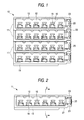
- the male block connector 10 comprises four male connector units 11 (hereinafter referred to as "male units") .
- the male units 11 are made of a synthetic resin, and have the same configuration.
- the male unit 11 has the configuration shown in Figs. 2 to 4, and has a hood portion 13 formed on and projecting from a front side of a flattened base portion 12 of a large transverse dimension.
- Six cavities 15 are formed in the base portion 12, and are spaced at predetermined intervals in the transverse (horizontal) direction.
- a male metal terminal 2, fixedly secured to an end of a wire 1 is inserted into each cavity 15 from a rear side (left side in Fig. 4) thereof, and is retained by a lance 16, formed on a bottom surface of the cavity 15, and therefore is received in the cavity against withdrawal, with its tab 3 projecting into the interior of the hood portion 3.
- a dovetail groove 18 is formed in an upper surface of the base portion 12 of the male unit 11, and extends from a left side edge thereof to a position spaced slightly from a right side edge thereof, and this dovetail groove has an open left end and a closed right end.
- a dovetail projection 19 for snugly fitting in the dovetail groove 18 is formed on a lower surface of the base portion 12, and extends from the left side edge thereof to a position spaced slightly from the right side edge thereof.
- An engagement projection 20 is formed on a bottom surface of the dovetail groove 18 at a right end portion thereof.
- An engagement recess 21 for fitting on the engagement projection 20 is formed in that portion of the surface of the dovetail projection 19 corresponding to the engagement projection 20.
- a left-hand surface (Fig. 3) of the engagement projection 20 is formed into a tapering (slanting) surface.
- a pair of upper and lower protective walls 23 are formed on a right side surface (when viewed from the front side) of the male unit 11, and extend from the front side thereof to a position slightly spaced from the rear side thereof.
- a lock arm 25 is provided between the pair of protective walls, and extends in a forward-rearward direction. This lock arm 25 can be swayed about a fulcrum 26 provided at a lengthwise central portion thereof.
- a hook 27 is formed at a distal end of this lock arm 25, and a cancellation portion 28 for forcibly elastically deforming the lock arm 25 so as to cancel its locked condition is formed at a rear end of the lock arm 25.
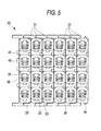
- the female block connector 30 comprises six female connector units 31 (hereinafter referred to as "female units").
- the female units 31 are also made of a synthetic resin, and have the same configuration.
- the female unit 31 has four reception projections 33 formed on and projecting from a front side of a flattened base portion 32 of a large vertical dimension, the reception projections 33 being juxtaposed at predetermined intervals in the vertical direction.
- the female unit 31 has a vertical dimension equal to the height of the assembled male block connector 10, and has a transverse (horizontal) dimension corresponding to the pitch of the cavities 15 in the male unit 11.
- a cavity 35 is formed in each reception projection 33, and is open to a rear surface of the base portion 32.
- a female metal terminal 5, fixedly secured to an end of a wire 1 is inserted into each cavity 35 from the rear side (right side in Fig. 8) thereof, and is retained by a lance 36, formed on a bottom surface of the cavity 35, and therefore is received in the cavity against withdrawal.
- the pitch of the cavities 35 (formed in the female unit 31) in the upward-downward direction (vertical direction) is equal to the pitch of the cavities 15 of the vertically-adjoining male units 11 of the assembled male block connector 10.
- the pitch of the cavities 15 of the male unit 11 is equal to the pitch of the cavities 35 of the horizontally-adjoining female units 31 of the assembled female block connector 30.
- Each row of six reception projections 33 of the horizontally-adjoining female units 31 of the assembled female block connector 30 can be fitted collectively in the hood portion 13 of the corresponding male unit 11.
- Retaining projections 38 are formed respectively on upper and lower surfaces of the base portion 32 of the female unit 31 at their respective right edge portions(when viewed from the front side thereof) .
- the retaining projection 38 has a vertical left side surface serving as a retaining surface, while a right side surface thereof is tapering (slanting), and serves as a guide surface.
- Retaining plates 39 are formed respectively on the upper and lower surfaces of the base portion 32 at their respective left edge portions, and extend in a left-hand direction, and each of the retaining plates 39 has a retaining hole 40 for fitting on the retaining projection 38.
- Ribs 42 are formed on the left side surface of the base portion 32, the rib 42 being provided between any two adjacent cavities 35.
- Fitting grooves 43 are formed in the right side surface of the base portion 32, and these fitting grooves 43 are fitted respectively on the corresponding ribs 42 so as to effect the positioning mainly in the forward-rearward direction.
- a lock projection 45 which is engageable with the hook 27 of the lock arm 25, is formed on the left side surface (when viewed from the front side) of the second reception projection 33 (counting from the top) of the female unit 31. As shown in Fig. 7, the lock projection 45 has a vertical rear surface and an upwardly-slanting front surface. An escape recess 47 for receiving the lock projection 45 is formed in the right side surface of the second reception projection 33 (counting from the top).
- a male-side wire harness is divided into four sub-harnesses, and six male metal terminals 2 are connected to an end of each of these sub-harnesses.
- the six male metal terminals 2 of each sub-harness are inserted and received respectively in the cavities 15 in the same (one) male unit 11.
- a female-side wire harness is divided into six sub-harnesses, and four female metal terminals 5 are connected to an end of each of these sub-harnesses .
- the four female metal terminals 5 of each sub-harness are inserted and received respectively in the cavities 35 in the same (one) female unit 31.
- the male units 11 are stacked one upon another in four rows as shown in Fig. 9. More specifically, the dovetail projection 19, formed on the lower surface of the upper male unit 11, is disposed in registry with the dovetail groove 18, formed in the upper surface of the lower male unit 11, and in this condition the upper male unit is pushed in a right-hand direction as indicated by an arrow.
- the engagement projection 20, formed at the dovetail groove 18, is fitted in the engagement recess 21 formed in the dovetail projection 19, so that the upper and lower male units 11 are combined together.
- the same procedure is repeated, thereby forming the male block connector 10 comprising the four male units 11 combined together in a vertically-stacked manner, as shown in Fig. 1.
- the female units 31 are combined together in six columns sequentially from the right as shown in Fig. 10. More specifically, the fitting grooves 43 in the left female unit 31 are disposed in registry with the ribs 42 on the right female unit 31, respectively, and then when the left female unit 31 is pushed, the retaining plates 39 of the right female unit 31 are elastically deformed, and slide respectively on the retaining projections 38 of the left female unit 31. When the left female unit 31 is pushed until the right and left female units 31 are stacked together, each of the retaining plates 39 is restored into its initial shape, and therefore the retaining projection 38 is fitted in the retaining hole 40, so that the right and left female units 31 are combined together.
- the same procedure is repeated, thereby forming the female block connector 30 comprising the six female units 31 combined together in a horizontally-stacked manner as shown in Fig. 5.
- the lock projection 45 on the right one of any two adjacent female units 31 is fitted in the escape recess 47 in the left female unit 31 for escaping purposes (see Fig. 11).
- reception projections 33 of the female units 31 are juxtaposed horizontally in a row, and therefore there are provided four rows of reception projections 33 in the vertical direction (upward-downward direction).
- the male and female block connectors 10 and 30, each thus assembled, are opposed to each other as shown in Fig. 11, and are fitted together.
- the four rows of reception projections 33 arranged in the vertical direction, are fitted into the hood portions 13 of the male units 11, respectively, and during this fitting operation, the second lock arm 25, counting from the top, abuts against the corresponding lock projection 45, and is elastically deformed to slide thereon.
- the rows of reception projections 33 are inserted a predetermined amount respectively into the hood portions 13 to be properly fitted therein, each mating pair of male and female metal terminals 2 and 5 are properly connected together as shown in Fig. 13.
- one wire harness WH1 is divided into four sub-harnesses SH1 to SH4 as shown in Fig. 13, and six male metal terminals 2, connected to each of these sub-harnesses, are received in the same male unit 11.
- the other wire harness WH2 is divided into six sub-harnesses, and four female metal terminals 5, connected to each of these sub-harnesses, are received in the same female unit 31.
- the four female metal terminals 5 of one sub-harness SH5 of the other wire harness WH2 can be connected in an assigned manner respectively to four male metal terminals 2 provided respectively at the four sub-harnesses SH1 to SH4 of the one wire harness WH1.
- the block connectors can be used for making connection between the metal terminals of the sub-harnesses of the pair of wire harnesses in an intricate manner when the pair of wire harnesses are connected together, and the number of the connectors can be prevented from increasing, and besides the operation for fitting the connectors together can be easily effected at one time.
- the male unit 11 has a relatively large thickness, and therefore the dovetail groove 18 and the dovetail projection 19 are used as means for combining the male units 11 together.
- the direction of combining the male units 11 together is perpendicular to the direction of fitting of the male and female block connectors 10 and 30. Therefore, even if a resistance is offered during the fitting of the male and female block connectors 10 and 30, the male units 11, combined together, are prevented from being disconnected from each other.
- the lock arms 25 are formed respectively on all of the male units 11 (the male side) whereas the lock projections 45 are formed respectively on all of the female units 31 (the female side).
- One of the lock arms and one of the lock projections are used, and the other lock arms are kept in an unused condition, and the other lock projections are received in the respective escape recesses 47.
- the male units 11 for forming the male block connector 10, as well as the female units 31 for forming the female block connector 30 have the same configuration, and therefore the production cost can be reduced.
Landscapes
- Connector Housings Or Holding Contact Members (AREA)
- Details Of Connecting Devices For Male And Female Coupling (AREA)
Abstract
Description
Claims (2)
- A connector comprising:wherein the other block connector comprises the connector units which are equal in number to said cavities in each connector unit of said one block connector, and are combined together in the horizontal direction, each of said connector units of said other block connector having a plurality of cavities which are equal in number to the rows of stacked connector units of said one block connector, and are arranged in a vertical direction.a pair of block connectors, each including a plurality of connector units combined together and fitted together; whereinone of said block connectors comprises the connector units stacked one upon another in a plurality of rows, each of said connector units having a plurality of cavities arranged in a horizontal direction; and
- The connector according to claim 1, wherein the direction of combining of said connector units in said block connector is perpendicular to the direction of fitting of said block connector relative to the mating block connector.
Applications Claiming Priority (2)
| Application Number | Priority Date | Filing Date | Title |
|---|---|---|---|
| JP2000328985A JP3759870B2 (en) | 2000-10-27 | 2000-10-27 | connector |
| JP2000328985 | 2000-10-27 |
Publications (3)
| Publication Number | Publication Date |
|---|---|
| EP1202393A2 true EP1202393A2 (en) | 2002-05-02 |
| EP1202393A3 EP1202393A3 (en) | 2003-05-28 |
| EP1202393B1 EP1202393B1 (en) | 2005-01-12 |
Family
ID=18805748
Family Applications (1)
| Application Number | Title | Priority Date | Filing Date |
|---|---|---|---|
| EP01125153A Expired - Lifetime EP1202393B1 (en) | 2000-10-27 | 2001-10-23 | Electrical connector |
Country Status (4)
| Country | Link |
|---|---|
| US (1) | US6488546B2 (en) |
| EP (1) | EP1202393B1 (en) |
| JP (1) | JP3759870B2 (en) |
| DE (1) | DE60108333T2 (en) |
Cited By (1)
| Publication number | Priority date | Publication date | Assignee | Title |
|---|---|---|---|---|
| EP1816709A1 (en) * | 2006-02-01 | 2007-08-08 | Sumitomo Wiring Systems, Ltd. | A connector, a connector assembly and a method of assembling a connector |
Families Citing this family (21)
| Publication number | Priority date | Publication date | Assignee | Title |
|---|---|---|---|---|
| FR2838879B1 (en) * | 2002-04-23 | 2004-06-04 | Entrelec | ELECTRONIC BOX CONNECTION DEVICE |
| US7004795B2 (en) * | 2003-08-07 | 2006-02-28 | Anderson Power Products | Powerpole connector assembly and methods thereof |
| JP4591228B2 (en) * | 2005-06-21 | 2010-12-01 | 住友電装株式会社 | connector |
| JP2007095360A (en) * | 2005-09-27 | 2007-04-12 | Yazaki Corp | Combined connector |
| USD573536S1 (en) | 2007-04-17 | 2008-07-22 | Traxxas Lp | Electrical connector |
| US7374460B1 (en) | 2007-04-17 | 2008-05-20 | Traxxas Lp | Electrical connector assembly |
| USD576557S1 (en) | 2007-04-17 | 2008-09-09 | Traxxas Lp | Electrical connector |
| US20090176382A1 (en) * | 2008-01-08 | 2009-07-09 | Keng-Hsing Chen | Electric Coupler for Camping Trailer |
| JP5091983B2 (en) * | 2010-06-16 | 2012-12-05 | 矢崎総業株式会社 | Lever fitting type connector |
| JP5813401B2 (en) * | 2011-07-27 | 2015-11-17 | 矢崎総業株式会社 | Connector and wire harness provided therewith |
| JP2013137922A (en) * | 2011-12-28 | 2013-07-11 | Tyco Electronics Japan Kk | Electric connector |
| US9246286B2 (en) * | 2013-09-25 | 2016-01-26 | Virginia Panel Corporation | High speed data module for high life cycle interconnect device |
| US11031724B2 (en) * | 2017-03-09 | 2021-06-08 | Sumitomo Wiring Systems, Ltd. | Stacked connector and wire harness |
| USD933014S1 (en) | 2020-03-16 | 2021-10-12 | Traxxas Lp | Electrical connector for a model vehicle |
| USD939442S1 (en) | 2020-03-16 | 2021-12-28 | Traxxas Lp | Electrical connector for a model vehicle |
| US11569589B2 (en) | 2020-04-07 | 2023-01-31 | Traxxas, L.P. | Electrical power tap connector |
| US11769828B2 (en) | 2020-10-28 | 2023-09-26 | Wolfspeed, Inc. | Gate trench power semiconductor devices having improved deep shield connection patterns |
| US11610991B2 (en) | 2020-10-28 | 2023-03-21 | Wolfspeed, Inc. | Gate trench power semiconductor devices having improved deep shield connection patterns |
| US12080790B2 (en) * | 2020-10-28 | 2024-09-03 | Wolfspeed, Inc. | Power semiconductor devices including angled gate trenches |
| USD1054383S1 (en) | 2022-09-07 | 2024-12-17 | Traxxas, L.P. | Electrical connector |
| USD1054382S1 (en) | 2022-09-07 | 2024-12-17 | Traxxas, L.P. | Electrical connector |
Family Cites Families (18)
| Publication number | Priority date | Publication date | Assignee | Title |
|---|---|---|---|---|
| FR2237328A2 (en) * | 1973-06-27 | 1975-02-07 | Weidmueller Kg C | Electrical terminal box - permits various arrangements of female sockets into which are plugged male pins |
| JP2981908B2 (en) | 1990-06-04 | 1999-11-22 | 住友電装株式会社 | Assembly method of wire harness and connector for wire harness |
| US5211565A (en) * | 1990-11-27 | 1993-05-18 | Cray Research, Inc. | High density interconnect apparatus |
| US5037330A (en) * | 1990-11-30 | 1991-08-06 | Amp Corporated | Stacked circular DIN connector |
| JP2592640Y2 (en) * | 1991-06-13 | 1999-03-24 | 住友電装株式会社 | ID connector |
| JP2553115Y2 (en) * | 1991-12-25 | 1997-11-05 | 住友電装株式会社 | connector |
| US5335146A (en) * | 1992-01-29 | 1994-08-02 | International Business Machines Corporation | High density packaging for device requiring large numbers of unique signals utilizing orthogonal plugging and zero insertion force connetors |
| JP3320986B2 (en) * | 1996-08-27 | 2002-09-03 | 矢崎総業株式会社 | Coupling connector |
| JP3625109B2 (en) * | 1996-08-30 | 2005-03-02 | 矢崎総業株式会社 | Connector connection structure |
| JP3178359B2 (en) * | 1996-11-12 | 2001-06-18 | 住友電装株式会社 | Block connector |
| JP3235489B2 (en) * | 1996-11-14 | 2001-12-04 | 住友電装株式会社 | Block connector |
| JP3330520B2 (en) * | 1997-08-20 | 2002-09-30 | 矢崎総業株式会社 | Coupling connector |
| US5984732A (en) * | 1997-11-14 | 1999-11-16 | Umax Computer Corporation | Method and apparatus for interconnection of modular electronic components |
| JP3410951B2 (en) * | 1998-02-20 | 2003-05-26 | 矢崎総業株式会社 | Electrical junction box |
| US6343950B1 (en) * | 1999-02-23 | 2002-02-05 | Mark E. Eginton | Connector arrays |
| JP3732683B2 (en) * | 1999-08-02 | 2006-01-05 | 矢崎総業株式会社 | Connector connection structure |
| JP3701517B2 (en) * | 1999-08-06 | 2005-09-28 | 矢崎総業株式会社 | Pressure welding connector and union connector |
| US6264501B1 (en) * | 1999-10-20 | 2001-07-24 | Tekcon Electronics Corp. | Connector assembly |
-
2000
- 2000-10-27 JP JP2000328985A patent/JP3759870B2/en not_active Expired - Fee Related
-
2001
- 2001-10-18 US US09/978,558 patent/US6488546B2/en not_active Expired - Fee Related
- 2001-10-23 EP EP01125153A patent/EP1202393B1/en not_active Expired - Lifetime
- 2001-10-23 DE DE60108333T patent/DE60108333T2/en not_active Expired - Fee Related
Cited By (1)
| Publication number | Priority date | Publication date | Assignee | Title |
|---|---|---|---|---|
| EP1816709A1 (en) * | 2006-02-01 | 2007-08-08 | Sumitomo Wiring Systems, Ltd. | A connector, a connector assembly and a method of assembling a connector |
Also Published As
| Publication number | Publication date |
|---|---|
| US6488546B2 (en) | 2002-12-03 |
| JP2002134212A (en) | 2002-05-10 |
| DE60108333D1 (en) | 2005-02-17 |
| DE60108333T2 (en) | 2005-12-22 |
| JP3759870B2 (en) | 2006-03-29 |
| US20020052152A1 (en) | 2002-05-02 |
| EP1202393A3 (en) | 2003-05-28 |
| EP1202393B1 (en) | 2005-01-12 |
Similar Documents
| Publication | Publication Date | Title |
|---|---|---|
| EP1202393B1 (en) | Electrical connector | |
| US6582256B2 (en) | Connector | |
| US4596436A (en) | Electrical connector housing assembly comprising housing frame containing housing modules | |
| US6645003B2 (en) | Joint connector | |
| US4963102A (en) | Electrical connector of the hermaphroditic type | |
| US4984998A (en) | High density electrical connector | |
| US6623309B2 (en) | Division connector | |
| US6881102B2 (en) | Terminal locking mechanism for hybrid electrical connector | |
| US7114997B2 (en) | Electrical connector | |
| EP1560298B1 (en) | A divided connector and connector assembly | |
| EP1524727A1 (en) | Electrical connector | |
| EP1816709B1 (en) | A connector, a connector assembly and a method of assembling a connector | |
| JPH08106944A (en) | Electrical connector and housing of the electrical connector | |
| US11108193B2 (en) | Connector and connector device | |
| US4971580A (en) | High density electrical connector with terminal retention latch | |
| US10622774B2 (en) | Joint connector | |
| US7112104B2 (en) | Electrical connector | |
| US20020193013A1 (en) | Connector | |
| EP0503947B1 (en) | An electric connector | |
| US11031724B2 (en) | Stacked connector and wire harness | |
| US6273746B1 (en) | Connector and a method for producing the same | |
| US9972921B2 (en) | Connector with sub-housing and uniting portion | |
| US4036544A (en) | Contact for multiple conductor connector | |
| US5564953A (en) | Divided-type multi-pole connector | |
| US7044813B2 (en) | Electrical connector with terminal rotation prevention |
Legal Events
| Date | Code | Title | Description |
|---|---|---|---|
| PUAI | Public reference made under article 153(3) epc to a published international application that has entered the european phase |
Free format text: ORIGINAL CODE: 0009012 |
|
| AK | Designated contracting states |
Kind code of ref document: A2 Designated state(s): AT BE CH CY DE DK ES FI FR GB GR IE IT LI LU MC NL PT SE TR |
|
| AX | Request for extension of the european patent |
Free format text: AL;LT;LV;MK;RO;SI |
|
| PUAL | Search report despatched |
Free format text: ORIGINAL CODE: 0009013 |
|
| AK | Designated contracting states |
Designated state(s): AT BE CH CY DE DK ES FI FR GB GR IE IT LI LU MC NL PT SE TR |
|
| AX | Request for extension of the european patent |
Extension state: AL LT LV MK RO SI |
|
| 17P | Request for examination filed |
Effective date: 20030826 |
|
| 17Q | First examination report despatched |
Effective date: 20031027 |
|
| AKX | Designation fees paid |
Designated state(s): DE FR GB IT |
|
| GRAP | Despatch of communication of intention to grant a patent |
Free format text: ORIGINAL CODE: EPIDOSNIGR1 |
|
| GRAS | Grant fee paid |
Free format text: ORIGINAL CODE: EPIDOSNIGR3 |
|
| GRAA | (expected) grant |
Free format text: ORIGINAL CODE: 0009210 |
|
| AK | Designated contracting states |
Kind code of ref document: B1 Designated state(s): DE FR GB IT |
|
| PG25 | Lapsed in a contracting state [announced via postgrant information from national office to epo] |
Ref country code: IT Free format text: LAPSE BECAUSE OF FAILURE TO SUBMIT A TRANSLATION OF THE DESCRIPTION OR TO PAY THE FEE WITHIN THE PRESCRIBED TIME-LIMIT;WARNING: LAPSES OF ITALIAN PATENTS WITH EFFECTIVE DATE BEFORE 2007 MAY HAVE OCCURRED AT ANY TIME BEFORE 2007. THE CORRECT EFFECTIVE DATE MAY BE DIFFERENT FROM THE ONE RECORDED. Effective date: 20050112 Ref country code: FR Free format text: LAPSE BECAUSE OF NON-PAYMENT OF DUE FEES Effective date: 20050112 |
|
| REG | Reference to a national code |
Ref country code: GB Ref legal event code: FG4D |
|
| REF | Corresponds to: |
Ref document number: 60108333 Country of ref document: DE Date of ref document: 20050217 Kind code of ref document: P |
|
| REG | Reference to a national code |
Ref country code: IE Ref legal event code: FG4D |
|
| PLBE | No opposition filed within time limit |
Free format text: ORIGINAL CODE: 0009261 |
|
| STAA | Information on the status of an ep patent application or granted ep patent |
Free format text: STATUS: NO OPPOSITION FILED WITHIN TIME LIMIT |
|
| 26N | No opposition filed |
Effective date: 20051013 |
|
| EN | Fr: translation not filed | ||
| PGFP | Annual fee paid to national office [announced via postgrant information from national office to epo] |
Ref country code: GB Payment date: 20071017 Year of fee payment: 7 |
|
| PGFP | Annual fee paid to national office [announced via postgrant information from national office to epo] |
Ref country code: DE Payment date: 20081016 Year of fee payment: 8 |
|
| GBPC | Gb: european patent ceased through non-payment of renewal fee |
Effective date: 20081023 |
|
| PG25 | Lapsed in a contracting state [announced via postgrant information from national office to epo] |
Ref country code: GB Free format text: LAPSE BECAUSE OF NON-PAYMENT OF DUE FEES Effective date: 20081023 |
|
| PG25 | Lapsed in a contracting state [announced via postgrant information from national office to epo] |
Ref country code: DE Free format text: LAPSE BECAUSE OF NON-PAYMENT OF DUE FEES Effective date: 20100501 |