EP1202316A1 - An improved remotely controlled circuit breaker - Google Patents
An improved remotely controlled circuit breaker Download PDFInfo
- Publication number
- EP1202316A1 EP1202316A1 EP00203673A EP00203673A EP1202316A1 EP 1202316 A1 EP1202316 A1 EP 1202316A1 EP 00203673 A EP00203673 A EP 00203673A EP 00203673 A EP00203673 A EP 00203673A EP 1202316 A1 EP1202316 A1 EP 1202316A1
- Authority
- EP
- European Patent Office
- Prior art keywords
- remotely controlled
- circuit breaker
- controlled circuit
- movable contact
- motion
- Prior art date
- Legal status (The legal status is an assumption and is not a legal conclusion. Google has not performed a legal analysis and makes no representation as to the accuracy of the status listed.)
- Granted
Links
Images



Classifications
-
- H—ELECTRICITY
- H01—ELECTRIC ELEMENTS
- H01H—ELECTRIC SWITCHES; RELAYS; SELECTORS; EMERGENCY PROTECTIVE DEVICES
- H01H71/00—Details of the protective switches or relays covered by groups H01H73/00 - H01H83/00
- H01H71/10—Operating or release mechanisms
- H01H71/66—Power reset mechanisms
- H01H71/70—Power reset mechanisms actuated by electric motor
-
- H—ELECTRICITY
- H01—ELECTRIC ELEMENTS
- H01H—ELECTRIC SWITCHES; RELAYS; SELECTORS; EMERGENCY PROTECTIVE DEVICES
- H01H57/00—Electrostrictive relays; Piezoelectric relays
Definitions
- the present invention relates to an improved circuit breaker. More particularly the present invention relates to an improved low voltage (i.e. for voltage values lower than 1KV) circuit breaker, which is remotely controlled during the closing operation.
- an improved low voltage (i.e. for voltage values lower than 1KV) circuit breaker which is remotely controlled during the closing operation.
- low voltage circuit breakers are aimed at interrupting the circulation of current in a power distribution line, (for example in case of fault). This is achieved by means of separating, generally using a suitable spring mechanism, two electric contacts that are serially connected with the power distribution line (opening operation). After an opening operation of the circuit breaker has been performed, it is necessary to bring again the circuit breaker to normal functioning conditions and, therefore, to couple the electric contacts (closing operation) of the circuit breaker, so as to allow the current to flow.
- the closing operation is generally performed by means of a manual closing mechanism. It is known that the manual closing operation can be, in some cases, quite difficult, particularly when the circuit breaker is placed in a difficulty accessible position or is placed quite far from the operator.
- Remotely controlled circuit breakers are commonly provided with a remotely controlled motor arrangement, which allows the operator to perform the closing operation, without the need of a manual intervention.
- a motor arrangement can be remotely activated, so as to generate a motion, which allows coupling the electric contacts by means of suitable mechanical arrangements. After the electric contacts are coupled, the motor arrangement is disengaged from the movable contact and the circuit breaker continues its normal functioning, till a new opening operation is performed.
- the mentioned remotely controlled motor arrangement generally comprises a remotely controlled electric motor, whose overall size and occupied volume is often relevant, due to the presence of the inductive/capacitor circuits and/or windings.
- the practice has shown that this fact makes often quite difficult to install a remotely controlled circuit breaker on a power distribution switchboard (in fact, at least a so-called four-modules case is generally needed for including a remotely controlled circuit breaker of the known type). Obviously, this provokes an increase of the installation costs.
- the presence of an electric motor makes necessary to provide for complex mechanical arrangements for transmitting the motion generated by the electric motor to the movable contact.
- the presence of complex mechanical arrangements implies obviously a further increase of the overall size.
- the reliability of the whole remotely controlled circuit breaker is necessarily decreased, due to a higher probability of mechanical faults.
- the complexity of the mechanical arrangements that are commonly adopted implies necessarily higher production costs.
- the main aim of the present invention is to provide a remotely controlled circuit breaker, which allows overcoming the drawbacks mentioned above.
- Another object of the present invention is to provide a remotely controlled circuit breaker, which is characterised by remarkably reduced overall size and volume.
- Another object of the present invention is to provide a remotely controlled circuit breaker, which allows achieving a strong simplification of the mechanical arrangements and operating elements that are needed for transmitting the motion of the movable contact, during the closing operation of the circuit breaker.
- Another object of the present invention is to provide a remotely controlled circuit breaker, which is characterised by a higher simplicity of installation and higher reliability levels.
- Not the least object of the present invention is to provide a remotely controlled circuit breaker, which is easy to fabricate at competitive costs.
- the present invention provides a remotely controlled circuit breaker, which comprises at least a fixed contact and a movable contact that is coupled/de-coupled with the fixed contact, respectively during the closing/opening operation of the remotely controlled circuit breaker.
- the remotely controlled circuit breaker according to the present invention, further comprises remotely controlled motor means for coupling, by means of motion transmission means, the movable contact to the fixed contact during a closing operation of the circuit breaker.
- the remotely controlled circuit breaker is characterized in that the remotely controlled motor means comprise at least a remotely controlled piezoelectric motor assembly.
- the remotely controlled piezoelectric motor assembly is operatively connected to the motion transmission means, so as to couple the movable contact to the fixed contact during a closing operation of the remotely controlled circuit breaker.
- FIG. 1 a block diagram illustrating the basic structure of the remotely controlled circuit breaker (reference 1), according to the present invention, is represented.
- the remotely controlled circuit breaker 1 comprises at least a fixed contact 3 and a movable contact 2.
- the movable contact 2 is coupled/uncoupled with the fixed contact 3 respectively during the closing/opening operation of the remotely controlled circuit breaker 1.
- the remotely controlled circuit breaker 1 comprises further remotely controlled motor means 4, for coupling, by means of motion transmission means 5, the movable contact 2 to the fixed contact 3, during a closing operation of the remotely controlled circuit breaker 1.
- the remotely controlled motor means 4 comprise at least a remotely controlled piezoelectric motor assembly 6, operatively connected to the motion transmission means 5, so as to couple the movable contact 2 with the fixed contact 3, during a closing operation of the remotely controlled circuit breaker 1.
- the remotely controlled piezoelectric motor assembly 6 comprises, advantageously, a stator arrangement 7, which includes at least a piezoelectric assembly 8, operatively connected to a stator frame 9.
- the remotely controlled piezoelectric motor assembly 6 comprises further a rotor arrangement 10, operatively connected the stator frame 9.
- the stator frame 9 comprises preferably a flange element 11.
- the flange element 11 is advantageously provided with a base wall 13 and a projecting wall 12, which protrudes from the base wall 13 in a substantially vertical manner.
- the piezoelectric assembly 8 comprises preferably one or more piezoelectric elements 15 that are mechanically coupled to the base wall 13.
- the piezoelectric elements 15 are advantageously excited by predefined excitation signals 16 (see also figure 1), so as to determine an elliptical motion 17 of the projecting wall 12.
- two different portions (not shown) of the piezoelectric elements 15 may be fed with excitation signals 16 that comprise two different ultrasonic signals that are shifted of 90°. Therefore, the piezoelectric elements 15 of each portion are forced to vibrate with a 90° phase-shift. The vibration is transmitted to the projecting wall 12 and two 90°-shifted "travelling waves" (not shown) on the projecting wall 12 are generated. In this manner, each point of the projecting wall 12 is subjected to an elliptical motion 17.
- the excitation signals 16 may be advantageously generated by a suitable electronic circuit 160, placed closed to the remotely controlled motor assembly 6.
- Remote control means 18 preferably placed in a position that can be easily accessed by the operator, generate activation signals 180 and transmit them to the electronic circuit 160.
- the transmission of the activation signals 180 may be performed according to the techniques that are known to those skilled in the art. Particularly, the transmission might be performed according to arrangements either of the traditional (electrical connection) kind or the wireless kind.
- the electronic circuit 160 may be integrated with the remote control means 18.
- the rotor arrangement 10 comprises a rotor disc 19 (not shown in figure 2 but illustrated in figures 3 and 4).
- the rotor disc 19 is mechanically coupled to the projecting wall 12, so as to be subjected to a motion of the rotational kind.
- the motion transmission means 5 preferably comprise a shaft element 20 mechanically connected to the rotor disc 19.
- the shaft element 20 might be mechanically coupled to the rotor disc 19 or, alternatively, be integrated with structure of the rotor disc 19.
- the motion transmission means 5 may also comprise a toggle element 21, which is operatively connected to the shaft element 20.
- the mechanical co-operation of the toggle element 21 with the shaft element 20, as it will be illustrated better in the following, may be achieved by means of a gear assembly 22.
- the motion transmission means 5 comprise preferably a kinematic chain 23, which operatively connects the toggle element 21 with the movable contact 2, at least during the closing operation of remotely controlled circuit breaker.
- the gear assembly 22 comprises preferably a pinion element 24, which is mechanically connected to the shaft element 20, and a rotating rack element 25, which is mechanically connected to the toggle element 21.
- the rotating rack element 25 mechanically cooperates with the pinion element 24, so as to transmit a motion to the toggle element 21.
- the rotating rack element 25 moves in direction of the arrow 27 and, consequently, the toggle element 21 is subjected to a motion according to the direction indicated by the arrow 28.
- the rotational motion of the rotor disc 19 is advantageously transformed in a motion 28 of the toggle element 21.
- the toggle element 21 is operatively connected with the movable contact 2, during a closing operation, by means of a kinematic chain 23.
- the kinematic chain 23 chain comprises preferably a bar mechanism 30, which includes one or more bar elements 31 mechanically connected between the movable contact 2 and the toggle element 21, so as to transmit a motion to the movable contact 2 during a closing operation.
- the bar mechanism 30 may comprise four bar elements 31. This is particularly advantageous in case the remotely controlled circuit breaker is of the magneto-thermal kind. However, according to the needs, the bar mechanism might comprise a different number of bar elements 31. For example, in case a remotely controlled residual current circuit breaker, five bar elements may be advantageously used.
- the kinematic chain 23 allows transmitting a motion to the movable contact 2, during a closing operation of the remote controlled circuit breaker, according to the present invention.
- the bar mechanism 31 can be arranged, for example establishing suitable rotational pivots, so as to transmit the motion of the toggle element 21 to the movable contact 2.
- a motion of the toggle element 21 in direction of the arrow 28 provokes the translation of the rotational pivot 35 may in direction of the arrow 32. This implies a decrease of the angle 34 between elements 31 a and 31 b of the bar mechanism 30.
- the movable contact is necessarily moved in direction of the arrow 33 and, therefore, coupled with the fixed contact 3.
- the toggle element 21 is mechanically disengaged from the kinematic chain 23.
- This can be obtained by means of trip mechanisms (not shown), whose arrangement is well known to those skilled in the art.
- the same trip mechanism is able to engage the kinematic chain 23 with the spring mechanism, which is generally used for performing the separation on the movable contact 2 from the fixed contact 3 (opening operation), when this is required.
- the remote controlled piezoelectric motor assembly 6 cannot have any influence on the opening operation of the remotely controlled circuit breaker, which is essentially determined by the mentioned spring mechanism, according to the common market requirements and/or standards.
- the remotely controlled piezoelectric motor assembly is brought to its initial position. This can be obtained by means of simply inverting the phase delay of the predefined excitation signals. During this motion, by means of the mentioned trip mechanism, the toggle element 21 is again mechanically engaged with the kinematic chain 23. In this manner, the piezoelectric motor assembly 6 can drive the closing operation of the remotely controlled circuit breaker.
- the toggle element 21 can be connected with the kinematic chain 23, in correspondence of the pivot point 35, which is, therefore, subjected to a motion 28, directly impressed by the toggle element 21.
- the kinematic chain 23 comprises a bar mechanism 30, which includes, in practice, only two bar elements (31 a , 31 b ), for transmitting a motion to the movable contact 2, during a closing operation of the remotely controlled circuit breaker, according to the present invention.
- the bar elements 31 c and 31 d are used only for the opening operation, once the toggle element 21 is disengaged from the kinematic chain 23.
- the toggle element 21 might be connected to the kinematic chain 23, in correspondence of other pivot points, such as for example the pivot point 36.
- the kinematic chain 23 comprises a bar mechanism 30, which includes only the bar element 31 a . It should be noticed that, in this case, it would be quite easier to control, by means of the piezoelectric motor assembly, also the opening operations of the remote controlled circuit breaker 1.
- the remotely controlled circuit breaker allows achieving the intended aims and objects.
- the adoption of the remotely controlled piezoelectric motor assembly 6 for moving the movable contact 2 allows avoiding the use of electromagnetic arrangements.
- the generation of motion by the remotely controlled piezoelectric motor assembly is mainly, as shown in the illustrated preferred embodiments, of the "mechanical" kind. This property allows achieving considerable advantages such as a remarkable reduction of the number of operating elements and, therefore, a remarkably reduction of the overall size and the volume occupied by the remotely controlled circuit breaker, according to the present invention.
- the practice has shown that the remotely controlled circuit breaker, according to the present invention, can be easily placed in a so-called "two modules" case.
- the remotely controlled circuit breaker according to the present invention, has proven also to be characterised by remarkably lower weight.
- the remotely controlled circuit breaker is particularly suitable for the use in low voltage applications, therefore for voltage values lower than 1 KV.
- the remotely controlled circuit breaker may be of different types, according to the different modes that can be chosen for determining the opening operations.
- the remotely controlled circuit breaker according to the present invention, can be used as a remotely controlled magneto-thermal circuit breaker or as a remotely controlled residual current circuit breaker.
- a different using mode is determined, according to the needs, by means of choosing a different opening mechanism.
- the remotely controlled circuit breaker can comprise one or more electric poles, each one comprising at least a movable contact 2 and a fixed contact 3.
- the remotely controlled circuit breaker can be of the three-pole kind or of the four-pole kind.
- remotely controlled circuit breaker according to the present invention, thus conceived is susceptible of numerous modifications and variations, all of which are within the scope of the inventive concept. All the details may also be replaced with other technically equivalent elements. In practice, the materials employed, so long as they are compatible with the specific use, as well as the dimensions, may be any according to the requirements and to the state of the art.
Landscapes
- Breakers (AREA)
- Selective Calling Equipment (AREA)
- Keying Circuit Devices (AREA)
- Remote Monitoring And Control Of Power-Distribution Networks (AREA)
Abstract
Description
- The present invention relates to an improved circuit breaker. More particularly the present invention relates to an improved low voltage (i.e. for voltage values lower than 1KV) circuit breaker, which is remotely controlled during the closing operation.
- It is known that low voltage circuit breakers are aimed at interrupting the circulation of current in a power distribution line, (for example in case of fault). This is achieved by means of separating, generally using a suitable spring mechanism, two electric contacts that are serially connected with the power distribution line (opening operation). After an opening operation of the circuit breaker has been performed, it is necessary to bring again the circuit breaker to normal functioning conditions and, therefore, to couple the electric contacts (closing operation) of the circuit breaker, so as to allow the current to flow. The closing operation is generally performed by means of a manual closing mechanism. It is known that the manual closing operation can be, in some cases, quite difficult, particularly when the circuit breaker is placed in a difficulty accessible position or is placed quite far from the operator. In order to solve this problem, remotely controlled circuit breakers have been introduced in the state of the art. Remotely controlled circuit breakers are commonly provided with a remotely controlled motor arrangement, which allows the operator to perform the closing operation, without the need of a manual intervention. In fact, a motor arrangement can be remotely activated, so as to generate a motion, which allows coupling the electric contacts by means of suitable mechanical arrangements. After the electric contacts are coupled, the motor arrangement is disengaged from the movable contact and the circuit breaker continues its normal functioning, till a new opening operation is performed.
- Known remotely controlled circuit breakers are characterised by some drawbacks.
- In fact, the mentioned remotely controlled motor arrangement generally comprises a remotely controlled electric motor, whose overall size and occupied volume is often relevant, due to the presence of the inductive/capacitor circuits and/or windings. The practice has shown that this fact makes often quite difficult to install a remotely controlled circuit breaker on a power distribution switchboard (in fact, at least a so-called four-modules case is generally needed for including a remotely controlled circuit breaker of the known type). Obviously, this provokes an increase of the installation costs. Further, the presence of an electric motor makes necessary to provide for complex mechanical arrangements for transmitting the motion generated by the electric motor to the movable contact. The presence of complex mechanical arrangements implies obviously a further increase of the overall size. Moreover, the reliability of the whole remotely controlled circuit breaker is necessarily decreased, due to a higher probability of mechanical faults. Further, the complexity of the mechanical arrangements that are commonly adopted implies necessarily higher production costs.
- The main aim of the present invention is to provide a remotely controlled circuit breaker, which allows overcoming the drawbacks mentioned above.
- Within this scope, another object of the present invention is to provide a remotely controlled circuit breaker, which is characterised by remarkably reduced overall size and volume.
- Another object of the present invention is to provide a remotely controlled circuit breaker, which allows achieving a strong simplification of the mechanical arrangements and operating elements that are needed for transmitting the motion of the movable contact, during the closing operation of the circuit breaker.
- Another object of the present invention is to provide a remotely controlled circuit breaker, which is characterised by a higher simplicity of installation and higher reliability levels.
- Not the least object of the present invention is to provide a remotely controlled circuit breaker, which is easy to fabricate at competitive costs.
- Thus, the present invention provides a remotely controlled circuit breaker, which comprises at least a fixed contact and a movable contact that is coupled/de-coupled with the fixed contact, respectively during the closing/opening operation of the remotely controlled circuit breaker. The remotely controlled circuit breaker, according to the present invention, further comprises remotely controlled motor means for coupling, by means of motion transmission means, the movable contact to the fixed contact during a closing operation of the circuit breaker. The remotely controlled circuit breaker, according to the present invention, is characterized in that the remotely controlled motor means comprise at least a remotely controlled piezoelectric motor assembly. The remotely controlled piezoelectric motor assembly is operatively connected to the motion transmission means, so as to couple the movable contact to the fixed contact during a closing operation of the remotely controlled circuit breaker.
- Further characteristics and advantages of the remotely controlled circuit breaker, according to the present invention, will be better described hereinafter, with particular reference to the enclosed figures, in which:
- figure 1 schematically illustrates a block diagram representing schematically the basic structure of the remotely controlled circuit breaker, according to the present invention;
- figure 2 schematically illustrates a preferred embodiment of a portion of the remotely controlled circuit breaker, according to the present invention;
- figure 3 schematically illustrates a block diagram representing schematically a preferred embodiment of another portion of the remotely controlled circuit breaker, according to the present invention;
- figure 4 schematically illustrates a preferred embodiment of another portion of the remotely controlled circuit breaker, according to the present invention;
- figure 5 schematically illustrates a preferred embodiment of another portion of the remotely controlled circuit breaker, according to the present invention;
- figure 6 schematically illustrates another preferred embodiment of another portion of the remotely controlled circuit breaker, according to the present invention.
-
- Referring to figure 1, a block diagram illustrating the basic structure of the remotely controlled circuit breaker (reference 1), according to the present invention, is represented.
- The remotely controlled
circuit breaker 1 comprises at least a fixedcontact 3 and amovable contact 2. Themovable contact 2 is coupled/uncoupled with the fixedcontact 3 respectively during the closing/opening operation of the remotely controlledcircuit breaker 1. - The remotely controlled
circuit breaker 1 comprises further remotely controlled motor means 4, for coupling, by means of motion transmission means 5, themovable contact 2 to the fixedcontact 3, during a closing operation of the remotely controlledcircuit breaker 1. The remotely controlled motor means 4 comprise at least a remotely controlledpiezoelectric motor assembly 6, operatively connected to the motion transmission means 5, so as to couple themovable contact 2 with the fixedcontact 3, during a closing operation of the remotely controlledcircuit breaker 1. - The remotely controlled
piezoelectric motor assembly 6, comprises, advantageously, astator arrangement 7, which includes at least a piezoelectric assembly 8, operatively connected to astator frame 9. The remotely controlledpiezoelectric motor assembly 6 comprises further arotor arrangement 10, operatively connected thestator frame 9. - Referring now to figure 2, according to a preferred embodiment of the remotely controlled
circuit breaker 1, thestator frame 9 comprises preferably aflange element 11. Theflange element 11 is advantageously provided with abase wall 13 and a projectingwall 12, which protrudes from thebase wall 13 in a substantially vertical manner. As illustrated in figure 2 (where only a portion of theflange element 11 is shown), the piezoelectric assembly 8 comprises preferably one or morepiezoelectric elements 15 that are mechanically coupled to thebase wall 13. Thepiezoelectric elements 15 are advantageously excited by predefined excitation signals 16 (see also figure 1), so as to determine anelliptical motion 17 of theprojecting wall 12. - In fact, advantageously, two different portions (not shown) of the
piezoelectric elements 15 may be fed withexcitation signals 16 that comprise two different ultrasonic signals that are shifted of 90°. Therefore, thepiezoelectric elements 15 of each portion are forced to vibrate with a 90° phase-shift. The vibration is transmitted to the projectingwall 12 and two 90°-shifted "travelling waves" (not shown) on the projectingwall 12 are generated. In this manner, each point of the projectingwall 12 is subjected to anelliptical motion 17. - The excitation signals 16 (see figure 1) may be advantageously generated by a suitable
electronic circuit 160, placed closed to the remotely controlledmotor assembly 6. - Remote control means 18, preferably placed in a position that can be easily accessed by the operator, generate
activation signals 180 and transmit them to theelectronic circuit 160. The transmission of theactivation signals 180 may be performed according to the techniques that are known to those skilled in the art. Particularly, the transmission might be performed according to arrangements either of the traditional (electrical connection) kind or the wireless kind. Alternatively, theelectronic circuit 160 may be integrated with the remote control means 18. - According to this embodiment of the present invention, the
rotor arrangement 10 comprises a rotor disc 19 (not shown in figure 2 but illustrated in figures 3 and 4). Therotor disc 19 is mechanically coupled to the projectingwall 12, so as to be subjected to a motion of the rotational kind. - According to a preferred embodiment of the present invention, which is schematically illustrated in the block diagram of figure 3, the motion transmission means 5 preferably comprise a
shaft element 20 mechanically connected to therotor disc 19. Theshaft element 20 might be mechanically coupled to therotor disc 19 or, alternatively, be integrated with structure of therotor disc 19. Preferably, the motion transmission means 5 may also comprise atoggle element 21, which is operatively connected to theshaft element 20. In practice, the mechanical co-operation of thetoggle element 21 with theshaft element 20, as it will be illustrated better in the following, may be achieved by means of agear assembly 22. Further, the motion transmission means 5 comprise preferably akinematic chain 23, which operatively connects thetoggle element 21 with themovable contact 2, at least during the closing operation of remotely controlled circuit breaker. - Referring now to figure 4, two different views of a preferred embodiment of the
gear assembly 22 are illustrated. Thegear assembly 22 comprises preferably apinion element 24, which is mechanically connected to theshaft element 20, and a rotatingrack element 25, which is mechanically connected to thetoggle element 21. The rotatingrack element 25 mechanically cooperates with thepinion element 24, so as to transmit a motion to thetoggle element 21. In fact, if therotor disc 19 rotates, for example in direction of thearrow 26, therotating rack element 25 moves in direction of thearrow 27 and, consequently, thetoggle element 21 is subjected to a motion according to the direction indicated by thearrow 28. Particularly, as it can be noticed in figure 4, the rotational motion of therotor disc 19 is advantageously transformed in amotion 28 of thetoggle element 21. - As mentioned above, the
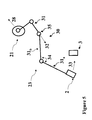
toggle element 21 is operatively connected with themovable contact 2, during a closing operation, by means of akinematic chain 23. With reference of the figure 5, thekinematic chain 23 chain comprises preferably abar mechanism 30, which includes one ormore bar elements 31 mechanically connected between themovable contact 2 and thetoggle element 21, so as to transmit a motion to themovable contact 2 during a closing operation. As illustrated in figure 5, thebar mechanism 30 may comprise fourbar elements 31. This is particularly advantageous in case the remotely controlled circuit breaker is of the magneto-thermal kind. However, according to the needs, the bar mechanism might comprise a different number ofbar elements 31. For example, in case a remotely controlled residual current circuit breaker, five bar elements may be advantageously used. As mentioned above, thekinematic chain 23 allows transmitting a motion to themovable contact 2, during a closing operation of the remote controlled circuit breaker, according to the present invention. Particularly, thebar mechanism 31 can be arranged, for example establishing suitable rotational pivots, so as to transmit the motion of thetoggle element 21 to themovable contact 2. With reference to the preferred embodiment illustrated in figure 5, a motion of thetoggle element 21 in direction of thearrow 28, provokes the translation of therotational pivot 35 may in direction of the arrow 32. This implies a decrease of theangle 34 betweenelements bar mechanism 30. In this manner, the movable contact is necessarily moved in direction of thearrow 33 and, therefore, coupled with the fixedcontact 3. - As soon as the
movable contact 2 is coupled with the fixedcontact 3, thetoggle element 21 is mechanically disengaged from thekinematic chain 23. This can be obtained by means of trip mechanisms (not shown), whose arrangement is well known to those skilled in the art. The same trip mechanism is able to engage thekinematic chain 23 with the spring mechanism, which is generally used for performing the separation on themovable contact 2 from the fixed contact 3 (opening operation), when this is required. In this manner, the remote controlledpiezoelectric motor assembly 6 cannot have any influence on the opening operation of the remotely controlled circuit breaker, which is essentially determined by the mentioned spring mechanism, according to the common market requirements and/or standards. - When an opening operation has been performed and, therefore, it is necessary to re-close the
electric contacts toggle element 21 is again mechanically engaged with thekinematic chain 23. In this manner, thepiezoelectric motor assembly 6 can drive the closing operation of the remotely controlled circuit breaker. - Alternatively, in a preferred embodiment of the remotely controlled circuit breaker, according to the present invention, the
toggle element 21 can be connected with thekinematic chain 23, in correspondence of thepivot point 35, which is, therefore, subjected to amotion 28, directly impressed by thetoggle element 21. In this case, thekinematic chain 23 comprises abar mechanism 30, which includes, in practice, only two bar elements (31a, 31b), for transmitting a motion to themovable contact 2, during a closing operation of the remotely controlled circuit breaker, according to the present invention. In fact, in this case, thebar elements toggle element 21 is disengaged from thekinematic chain 23. Accordingly, thetoggle element 21 might be connected to thekinematic chain 23, in correspondence of other pivot points, such as for example thepivot point 36. In this case, thekinematic chain 23 comprises abar mechanism 30, which includes only thebar element 31a. It should be noticed that, in this case, it would be quite easier to control, by means of the piezoelectric motor assembly, also the opening operations of the remote controlledcircuit breaker 1. - The remotely controlled circuit breaker, according to the present invention, allows achieving the intended aims and objects.
- In fact, the adoption of the remotely controlled
piezoelectric motor assembly 6 for moving themovable contact 2 allows avoiding the use of electromagnetic arrangements. In fact, the generation of motion by the remotely controlled piezoelectric motor assembly is mainly, as shown in the illustrated preferred embodiments, of the "mechanical" kind. This property allows achieving considerable advantages such as a remarkable reduction of the number of operating elements and, therefore, a remarkably reduction of the overall size and the volume occupied by the remotely controlled circuit breaker, according to the present invention. In fact, the practice has shown that the remotely controlled circuit breaker, according to the present invention, can be easily placed in a so-called "two modules" case. - Moreover, due the absence of electromagnetic arrangements, which require the adoption of huge winding structures, the remotely controlled circuit breaker, according to the present invention, has proven also to be characterised by remarkably lower weight. These facts, allows obtaining relatively lower fabrication and installation costs.
- Further, the remarkable reduction of operating elements has proven to increase the operation reliability and high torque levels at low speed and relatively reduced response times can be easily achieved. This implies a remarkable increase of the operation performance.
- The remotely controlled circuit breaker, according to the present invention, is particularly suitable for the use in low voltage applications, therefore for voltage values lower than 1 KV.
- Due to the fact that the use of the
piezoelectric motor assembly 6 influences substantially only the closing operations, the remotely controlled circuit breaker may be of different types, according to the different modes that can be chosen for determining the opening operations. Thus, the remotely controlled circuit breaker, according to the present invention, can be used as a remotely controlled magneto-thermal circuit breaker or as a remotely controlled residual current circuit breaker. As mentioned above, in this case, a different using mode is determined, according to the needs, by means of choosing a different opening mechanism. - The remotely controlled circuit breaker, according to the present invention, can comprise one or more electric poles, each one comprising at least a
movable contact 2 and afixed contact 3. Particularly, the remotely controlled circuit breaker, according to the present invention, can be of the three-pole kind or of the four-pole kind. - The remotely controlled circuit breaker, according to the present invention, thus conceived is susceptible of numerous modifications and variations, all of which are within the scope of the inventive concept. All the details may also be replaced with other technically equivalent elements. In practice, the materials employed, so long as they are compatible with the specific use, as well as the dimensions, may be any according to the requirements and to the state of the art.
Claims (18)
- A remotely controlled circuit breaker comprising:characterized in that said remotely controlled motor means comprise at least a remotely controlled piezoelectric motor assembly, said remotely controlled piezoelectric motor being operatively connected to said motion transmission means, so as to couple said movable contact to said fixed contact during a closing operation of said remotely controlled circuit breaker.at least a fixed contact and a movable contact, said movable contact being coupled/uncoupled with said fixed contact, respectively during the closing/opening operation of said remotely controlled circuit breaker; andremotely controlled motor means for coupling, by means of motion transmission means, said movable contact to said fixed contact during a closing operation of said remotely controlled circuit breaker;
- A remotely controlled circuit breaker, according to claim 1, characterized in that said remotely controlled piezoelectric motor assembly, comprises:a stator arrangement comprising at least a piezoelectric assembly operatively connected to a stator frame; anda rotor arrangement, operatively connected said stator frame.
- A remotely controlled circuit breaker, according to claim 2, characterized in that said stator frame comprises a flange element provided with a base wall and a projecting wall, said projecting wall protruding in a substantially vertical manner from said base wall.
- A remotely controlled circuit breaker, according to one or more of claims from 2 to 3, characterized in that said piezoelectric assembly comprises one or more piezoelectric elements mechanically coupled to said base wall, said piezoelectric elements being excited by predefined excitation signals, so as to determine an elliptical motion of said projecting wall.
- A remotely controlled circuit breaker, according to one or more of claims from 2 to 4, characterized in that said rotor arrangement comprises a rotor disc, said rotor disc being mechanically coupled said projecting wall, so as to be subjected to a motion of the rotational kind.
- A remotely controlled circuit breaker, according to one or more of claims from 2 to 5, characterized in that said remotely controlled piezoelectric motor assembly is connected to an electronic circuit, said electronic circuit generating said predefined excitation signals and/or transmitting said predefined excitation signals to said plurality of piezoelectric elements.
- A remotely controlled circuit breaker, according to one or more of claims from 2 to 6, characterized in that said electronic circuit is connected to remote control means, said remote control means generating predefined activation signals and/or transmitting said predefined activation signals to said electronic circuit.
- A remotely controlled circuit breaker, according to one or more of the previous claims, characterized in that said motion transmission means comprises at least:a shaft element mechanically connected to said rotor disc; anda toggle element operatively connected to said shaft element; anda kinematic chain for operatively connecting said toggle element with said movable contact, at least during a closing operation of said remotely controlled circuit breaker.
- A remotely controlled circuit breaker, according to claim 8, characterized in that said motion transmission means comprise a gear assembly for operatively connecting said toggle element with said shaft element.
- A remotely controlled circuit breaker, according to claim 9, characterized in that said gear assembly comprises at least:a pinion element mechanically connected to said shaft element; anda rotating rack element mechanically connected to said toggle element, said rotating rack element mechanically cooperating with said pinion element, so as to transmit a motion to said toggle element.
- A remotely controlled circuit breaker, according to one or more claims from 8 to 10, characterized in that said kinematic chain comprises a bar mechanism comprising one or more bar elements, mechanically connected between said movable contact and said toggle element, so as to transmit a motion to said movable contact, at least during a closing operation of said of said remotely controlled circuit breaker.
- A remotely controlled circuit breaker, according to claim 11, characterized in that said bar mechanism comprises a single bar element.
- A remotely controlled circuit breaker, according to claim 11, characterized in that said bar mechanism comprises two bar elements.
- A remotely controlled circuit breaker, according to claim 11, characterized in that said bar mechanism comprises four bar elements.
- A remotely controlled circuit breaker, according to claim 11, characterized in that said bar mechanism comprises five bar elements.
- A remotely controlled circuit breaker, according to one or more of claims from 8 to 15, characterized in that said toggle element is mechanically disengaged from said kinematic chain when said movable contact is coupled with said fixed contact.
- A remotely controlled circuit breaker, according to one or more of the previous claims, characterized in that it is a remotely controlled magneto-thermal circuit breaker.
- A remotely controlled circuit breaker, according to one or more of claims from 1 to 16, characterized in that it is a remotely controlled residual current circuit breaker.
Priority Applications (4)
| Application Number | Priority Date | Filing Date | Title |
|---|---|---|---|
| EP00203673A EP1202316B1 (en) | 2000-10-23 | 2000-10-23 | An improved remotely controlled circuit breaker |
| AT00203673T ATE363130T1 (en) | 2000-10-23 | 2000-10-23 | AN IMPROVED REMOTE CONTROLLED CIRCUIT SWITCH |
| DE60034949T DE60034949T2 (en) | 2000-10-23 | 2000-10-23 | An improved remote controlled circuit breaker |
| CN01137126.9A CN1227682C (en) | 2000-10-23 | 2001-10-23 | remote circuit breaker |
Applications Claiming Priority (1)
| Application Number | Priority Date | Filing Date | Title |
|---|---|---|---|
| EP00203673A EP1202316B1 (en) | 2000-10-23 | 2000-10-23 | An improved remotely controlled circuit breaker |
Publications (2)
| Publication Number | Publication Date |
|---|---|
| EP1202316A1 true EP1202316A1 (en) | 2002-05-02 |
| EP1202316B1 EP1202316B1 (en) | 2007-05-23 |
Family
ID=8172164
Family Applications (1)
| Application Number | Title | Priority Date | Filing Date |
|---|---|---|---|
| EP00203673A Expired - Lifetime EP1202316B1 (en) | 2000-10-23 | 2000-10-23 | An improved remotely controlled circuit breaker |
Country Status (4)
| Country | Link |
|---|---|
| EP (1) | EP1202316B1 (en) |
| CN (1) | CN1227682C (en) |
| AT (1) | ATE363130T1 (en) |
| DE (1) | DE60034949T2 (en) |
Citations (6)
| Publication number | Priority date | Publication date | Assignee | Title |
|---|---|---|---|---|
| US2864912A (en) * | 1955-06-23 | 1958-12-16 | Ite Circuit Breaker Ltd | Motor operated circuit breaker |
| US5170088A (en) * | 1989-06-23 | 1992-12-08 | Alps Electric Co., Ltd. | Driving structure for electronic parts in a mechanism |
| US5180051A (en) * | 1991-06-28 | 1993-01-19 | Square D Company | Remote control circuit breaker |
| US5457351A (en) * | 1991-10-31 | 1995-10-10 | Matsushita Electric Industrial Co., Ltd. | Ultrasonic motor |
| US5945769A (en) * | 1991-08-26 | 1999-08-31 | Canon Kabushiki Kaisha | Wave driven motor |
| WO1999062090A1 (en) * | 1998-05-26 | 1999-12-02 | Pbt (Ip) Limited | Piezo ceramic operated mechanism |
Family Cites Families (1)
| Publication number | Priority date | Publication date | Assignee | Title |
|---|---|---|---|---|
| DE69929947T2 (en) * | 1999-06-04 | 2006-10-19 | Norbert Beyrard France (Sarl) | Switch driven by a piezoelectric motor |
-
2000
- 2000-10-23 DE DE60034949T patent/DE60034949T2/en not_active Expired - Lifetime
- 2000-10-23 AT AT00203673T patent/ATE363130T1/en not_active IP Right Cessation
- 2000-10-23 EP EP00203673A patent/EP1202316B1/en not_active Expired - Lifetime
-
2001
- 2001-10-23 CN CN01137126.9A patent/CN1227682C/en not_active Expired - Fee Related
Patent Citations (6)
| Publication number | Priority date | Publication date | Assignee | Title |
|---|---|---|---|---|
| US2864912A (en) * | 1955-06-23 | 1958-12-16 | Ite Circuit Breaker Ltd | Motor operated circuit breaker |
| US5170088A (en) * | 1989-06-23 | 1992-12-08 | Alps Electric Co., Ltd. | Driving structure for electronic parts in a mechanism |
| US5180051A (en) * | 1991-06-28 | 1993-01-19 | Square D Company | Remote control circuit breaker |
| US5945769A (en) * | 1991-08-26 | 1999-08-31 | Canon Kabushiki Kaisha | Wave driven motor |
| US5457351A (en) * | 1991-10-31 | 1995-10-10 | Matsushita Electric Industrial Co., Ltd. | Ultrasonic motor |
| WO1999062090A1 (en) * | 1998-05-26 | 1999-12-02 | Pbt (Ip) Limited | Piezo ceramic operated mechanism |
Also Published As
| Publication number | Publication date |
|---|---|
| DE60034949D1 (en) | 2007-07-05 |
| CN1227682C (en) | 2005-11-16 |
| DE60034949T2 (en) | 2008-01-24 |
| EP1202316B1 (en) | 2007-05-23 |
| ATE363130T1 (en) | 2007-06-15 |
| CN1350314A (en) | 2002-05-22 |
Similar Documents
| Publication | Publication Date | Title |
|---|---|---|
| RU2249874C2 (en) | Vacuum switch | |
| KR920003958B1 (en) | Remote-controlled circuit breaker | |
| JP2012043540A (en) | Air circuit breaker | |
| US20100073113A1 (en) | Electromagnet Assembly Directly Driving Latch Of An Electronic Circuit Breaker | |
| CN105244234A (en) | Switching-off and switching-on actuating structure of miniature circuit breaker controller | |
| AU702311B2 (en) | Circuit interrupter arrangement | |
| CN101971281A (en) | Multi-pole armature interlock for circuit breakers | |
| US20250104944A1 (en) | Circuit breaker having vacuum interrupters and single-phase control with magnetic actuators and associated method | |
| TWI313530B (en) | ||
| EP1202316B1 (en) | An improved remotely controlled circuit breaker | |
| CN113948349B (en) | Piezoelectric tripping mechanism for circuit breaker | |
| JPWO2011086670A1 (en) | Electromagnetic operation switchgear | |
| AU2003261668B2 (en) | Drive mechanism for switching installation and method for operating it | |
| US4247745A (en) | Vacuum-type contactor assembly | |
| US3502834A (en) | Vacuum recloser having lightweight,rugged skeletal housing | |
| KR970006444B1 (en) | Electromagnetic switch | |
| US20060220470A1 (en) | Device for actuating an electrical switchgear | |
| CN210743891U (en) | Leakage release for circuit breaker | |
| US4166938A (en) | Drive for high speed disconnect switch | |
| KR20050065798A (en) | Vacuum circuit breaker using permanent magnetic actuator | |
| KR100492753B1 (en) | Permanent magnetic actuator of vaccum circuit breaker | |
| JP3314000B2 (en) | Gas insulated switchgear | |
| CN114141590A (en) | Medium voltage circuit breaker | |
| CA2994123C (en) | Electrical enclosure, and switching assembly and transfer assembly therefor | |
| CN121306829A (en) | An electric operating mechanism and disconnect switch |
Legal Events
| Date | Code | Title | Description |
|---|---|---|---|
| PUAI | Public reference made under article 153(3) epc to a published international application that has entered the european phase |
Free format text: ORIGINAL CODE: 0009012 |
|
| AK | Designated contracting states |
Kind code of ref document: A1 Designated state(s): AT BE CH CY DE DK ES FI FR GB GR IE IT LI LU MC NL PT SE |
|
| AX | Request for extension of the european patent |
Free format text: AL;LT;LV;MK;RO;SI |
|
| 17P | Request for examination filed |
Effective date: 20021029 |
|
| AKX | Designation fees paid |
Free format text: AT BE CH CY DE DK ES FI FR GB GR IE IT LI LU MC NL PT SE |
|
| GRAP | Despatch of communication of intention to grant a patent |
Free format text: ORIGINAL CODE: EPIDOSNIGR1 |
|
| GRAS | Grant fee paid |
Free format text: ORIGINAL CODE: EPIDOSNIGR3 |
|
| GRAA | (expected) grant |
Free format text: ORIGINAL CODE: 0009210 |
|
| AK | Designated contracting states |
Kind code of ref document: B1 Designated state(s): AT BE CH CY DE DK ES FI FR GB GR IE IT LI LU MC NL PT SE |
|
| PG25 | Lapsed in a contracting state [announced via postgrant information from national office to epo] |
Ref country code: LI Free format text: LAPSE BECAUSE OF FAILURE TO SUBMIT A TRANSLATION OF THE DESCRIPTION OR TO PAY THE FEE WITHIN THE PRESCRIBED TIME-LIMIT Effective date: 20070523 Ref country code: CH Free format text: LAPSE BECAUSE OF FAILURE TO SUBMIT A TRANSLATION OF THE DESCRIPTION OR TO PAY THE FEE WITHIN THE PRESCRIBED TIME-LIMIT Effective date: 20070523 Ref country code: FI Free format text: LAPSE BECAUSE OF FAILURE TO SUBMIT A TRANSLATION OF THE DESCRIPTION OR TO PAY THE FEE WITHIN THE PRESCRIBED TIME-LIMIT Effective date: 20070523 |
|
| REG | Reference to a national code |
Ref country code: GB Ref legal event code: FG4D |
|
| REG | Reference to a national code |
Ref country code: CH Ref legal event code: EP |
|
| REG | Reference to a national code |
Ref country code: IE Ref legal event code: FG4D |
|
| REF | Corresponds to: |
Ref document number: 60034949 Country of ref document: DE Date of ref document: 20070705 Kind code of ref document: P |
|
| PG25 | Lapsed in a contracting state [announced via postgrant information from national office to epo] |
Ref country code: SE Free format text: LAPSE BECAUSE OF FAILURE TO SUBMIT A TRANSLATION OF THE DESCRIPTION OR TO PAY THE FEE WITHIN THE PRESCRIBED TIME-LIMIT Effective date: 20070823 |
|
| PG25 | Lapsed in a contracting state [announced via postgrant information from national office to epo] |
Ref country code: ES Free format text: LAPSE BECAUSE OF FAILURE TO SUBMIT A TRANSLATION OF THE DESCRIPTION OR TO PAY THE FEE WITHIN THE PRESCRIBED TIME-LIMIT Effective date: 20070903 |
|
| ET | Fr: translation filed | ||
| NLV1 | Nl: lapsed or annulled due to failure to fulfill the requirements of art. 29p and 29m of the patents act | ||
| PG25 | Lapsed in a contracting state [announced via postgrant information from national office to epo] |
Ref country code: AT Free format text: LAPSE BECAUSE OF FAILURE TO SUBMIT A TRANSLATION OF THE DESCRIPTION OR TO PAY THE FEE WITHIN THE PRESCRIBED TIME-LIMIT Effective date: 20070523 |
|
| REG | Reference to a national code |
Ref country code: CH Ref legal event code: PL |
|
| PG25 | Lapsed in a contracting state [announced via postgrant information from national office to epo] |
Ref country code: BE Free format text: LAPSE BECAUSE OF FAILURE TO SUBMIT A TRANSLATION OF THE DESCRIPTION OR TO PAY THE FEE WITHIN THE PRESCRIBED TIME-LIMIT Effective date: 20070523 |
|
| PG25 | Lapsed in a contracting state [announced via postgrant information from national office to epo] |
Ref country code: PT Free format text: LAPSE BECAUSE OF FAILURE TO SUBMIT A TRANSLATION OF THE DESCRIPTION OR TO PAY THE FEE WITHIN THE PRESCRIBED TIME-LIMIT Effective date: 20071023 Ref country code: NL Free format text: LAPSE BECAUSE OF FAILURE TO SUBMIT A TRANSLATION OF THE DESCRIPTION OR TO PAY THE FEE WITHIN THE PRESCRIBED TIME-LIMIT Effective date: 20070523 Ref country code: DK Free format text: LAPSE BECAUSE OF FAILURE TO SUBMIT A TRANSLATION OF THE DESCRIPTION OR TO PAY THE FEE WITHIN THE PRESCRIBED TIME-LIMIT Effective date: 20070523 |
|
| PLBE | No opposition filed within time limit |
Free format text: ORIGINAL CODE: 0009261 |
|
| STAA | Information on the status of an ep patent application or granted ep patent |
Free format text: STATUS: NO OPPOSITION FILED WITHIN TIME LIMIT |
|
| 26N | No opposition filed |
Effective date: 20080226 |
|
| PG25 | Lapsed in a contracting state [announced via postgrant information from national office to epo] |
Ref country code: GR Free format text: LAPSE BECAUSE OF FAILURE TO SUBMIT A TRANSLATION OF THE DESCRIPTION OR TO PAY THE FEE WITHIN THE PRESCRIBED TIME-LIMIT Effective date: 20070824 |
|
| PG25 | Lapsed in a contracting state [announced via postgrant information from national office to epo] |
Ref country code: MC Free format text: LAPSE BECAUSE OF NON-PAYMENT OF DUE FEES Effective date: 20071031 |
|
| GBPC | Gb: european patent ceased through non-payment of renewal fee |
Effective date: 20071023 |
|
| PG25 | Lapsed in a contracting state [announced via postgrant information from national office to epo] |
Ref country code: IE Free format text: LAPSE BECAUSE OF NON-PAYMENT OF DUE FEES Effective date: 20071023 |
|
| PG25 | Lapsed in a contracting state [announced via postgrant information from national office to epo] |
Ref country code: GB Free format text: LAPSE BECAUSE OF NON-PAYMENT OF DUE FEES Effective date: 20071023 |
|
| PG25 | Lapsed in a contracting state [announced via postgrant information from national office to epo] |
Ref country code: CY Free format text: LAPSE BECAUSE OF FAILURE TO SUBMIT A TRANSLATION OF THE DESCRIPTION OR TO PAY THE FEE WITHIN THE PRESCRIBED TIME-LIMIT Effective date: 20070523 |
|
| PG25 | Lapsed in a contracting state [announced via postgrant information from national office to epo] |
Ref country code: LU Free format text: LAPSE BECAUSE OF NON-PAYMENT OF DUE FEES Effective date: 20071023 |
|
| PGFP | Annual fee paid to national office [announced via postgrant information from national office to epo] |
Ref country code: DE Payment date: 20141022 Year of fee payment: 15 Ref country code: FR Payment date: 20141022 Year of fee payment: 15 |
|
| PGFP | Annual fee paid to national office [announced via postgrant information from national office to epo] |
Ref country code: IT Payment date: 20141027 Year of fee payment: 15 |
|
| REG | Reference to a national code |
Ref country code: DE Ref legal event code: R119 Ref document number: 60034949 Country of ref document: DE |
|
| PG25 | Lapsed in a contracting state [announced via postgrant information from national office to epo] |
Ref country code: IT Free format text: LAPSE BECAUSE OF NON-PAYMENT OF DUE FEES Effective date: 20151023 Ref country code: DE Free format text: LAPSE BECAUSE OF NON-PAYMENT OF DUE FEES Effective date: 20160503 |
|
| REG | Reference to a national code |
Ref country code: FR Ref legal event code: ST Effective date: 20160630 |
|
| PG25 | Lapsed in a contracting state [announced via postgrant information from national office to epo] |
Ref country code: FR Free format text: LAPSE BECAUSE OF NON-PAYMENT OF DUE FEES Effective date: 20151102 |