EP1202268A1 - Device for recording or reproducing signal on or from disk - Google Patents
Device for recording or reproducing signal on or from disk Download PDFInfo
- Publication number
- EP1202268A1 EP1202268A1 EP00944299A EP00944299A EP1202268A1 EP 1202268 A1 EP1202268 A1 EP 1202268A1 EP 00944299 A EP00944299 A EP 00944299A EP 00944299 A EP00944299 A EP 00944299A EP 1202268 A1 EP1202268 A1 EP 1202268A1
- Authority
- EP
- European Patent Office
- Prior art keywords
- holder
- lock slide
- release piece
- cartridge
- release
- Prior art date
- Legal status (The legal status is an assumption and is not a legal conclusion. Google has not performed a legal analysis and makes no representation as to the accuracy of the status listed.)
- Withdrawn
Links
- 230000037431 insertion Effects 0.000 claims description 3
- 238000003780 insertion Methods 0.000 claims description 3
- 230000003247 decreasing effect Effects 0.000 claims description 2
- 238000005452 bending Methods 0.000 description 4
- 239000002184 metal Substances 0.000 description 4
- 230000000452 restraining effect Effects 0.000 description 3
- 238000010276 construction Methods 0.000 description 1
- 230000000994 depressogenic effect Effects 0.000 description 1
- 230000003292 diminished effect Effects 0.000 description 1
- 238000009434 installation Methods 0.000 description 1
- 238000009877 rendering Methods 0.000 description 1
Images


Classifications
-
- G—PHYSICS
- G11—INFORMATION STORAGE
- G11B—INFORMATION STORAGE BASED ON RELATIVE MOVEMENT BETWEEN RECORD CARRIER AND TRANSDUCER
- G11B17/00—Guiding record carriers not specifically of filamentary or web form, or of supports therefor
- G11B17/02—Details
- G11B17/04—Feeding or guiding single record carrier to or from transducer unit
-
- G—PHYSICS
- G11—INFORMATION STORAGE
- G11B—INFORMATION STORAGE BASED ON RELATIVE MOVEMENT BETWEEN RECORD CARRIER AND TRANSDUCER
- G11B17/00—Guiding record carriers not specifically of filamentary or web form, or of supports therefor
- G11B17/02—Details
- G11B17/04—Feeding or guiding single record carrier to or from transducer unit
- G11B17/041—Feeding or guiding single record carrier to or from transducer unit specially adapted for discs contained within cartridges
- G11B17/043—Direct insertion, i.e. without external loading means
-
- G—PHYSICS
- G11—INFORMATION STORAGE
- G11B—INFORMATION STORAGE BASED ON RELATIVE MOVEMENT BETWEEN RECORD CARRIER AND TRANSDUCER
- G11B17/00—Guiding record carriers not specifically of filamentary or web form, or of supports therefor
- G11B17/02—Details
- G11B17/04—Feeding or guiding single record carrier to or from transducer unit
- G11B17/041—Feeding or guiding single record carrier to or from transducer unit specially adapted for discs contained within cartridges
- G11B17/044—Indirect insertion, i.e. with external loading means
- G11B17/046—Indirect insertion, i.e. with external loading means with pivoting loading means
- G11B17/0466—Indirect insertion, i.e. with external loading means with pivoting loading means with opening mechanism of the cartridge shutter
-
- G—PHYSICS
- G11—INFORMATION STORAGE
- G11B—INFORMATION STORAGE BASED ON RELATIVE MOVEMENT BETWEEN RECORD CARRIER AND TRANSDUCER
- G11B23/00—Record carriers not specific to the method of recording or reproducing; Accessories, e.g. containers, specially adapted for co-operation with the recording or reproducing apparatus ; Intermediate mediums; Apparatus or processes specially adapted for their manufacture
- G11B23/02—Containers; Storing means both adapted to cooperate with the recording or reproducing means
- G11B23/03—Containers for flat record carriers
- G11B23/0301—Details
- G11B23/0311—Wrong insertion preventing means
Definitions
- the present invention relates to signal recording or reproduction devices for disks enclosed in cartridges.
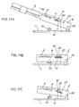
- FIGS. 11A, 11B and 11C are side elevations of a conventional signal recording or reproduction device for disks.
- a holder 2 is pivotally supported at one end thereof by a chassis 1 provided with a turntable 73.
- a cartridge 6 having the disk enclosed therein is inserted into the holder 2.
- a lock slide 4 to be pushed by the cartridge 6 is provided on the holder 2 and movable in cartridge inserting and unloading directions. As will be described later, the lock slide 4 holds the cartridge 6 as inserted in the holder 2, and is biased in the cartridge unloading direction by a tension spring 8 in engagement with the slide 4 and the holder 2.
- the cartridge inserting direction will be referred to as "front,” and the unloading direction as "rear.”
- the lock slide 4 is provided at its front end with an engaging hook 40 which is downwardly deflectable for deformation. Positioned in front of the engaging hook 40 is a lug 23 projecting from the holder 2. When the lock slide 4 is moved forward against the tension spring 8 by the insertion of the cartridge into the holder 2, the engaging hook 40 deflects once and thereafter comes into engagement with the lug 23 as seen in FIG. 11B. When the holder 2 is pivotally moved down, the turntable 73 on the chassis 1 faces the bottom surface of the holder 2, and the device is made ready to record or reproduce signals.
- release means 10 which will be described later.
- the release means 10 disengages the hook 40 from engagement with the lug 23.
- the lock slide 4 is moved rearward by the tension spring 8 and returned to the position shown in FIG. 11A.
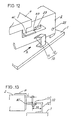
- FIG. 12 is a perspective view of the release means 10 and a primary portion of the holder 2.
- the engaging hook 40 of the lock slide 4 has a push plate 41 projecting laterally from the hood base end.
- the release means 10 is formed by bending a metal plate.
- a support wall 12 upstanding from the chassis 1 has a release piece 11 projecting inward and slanting downward.
- FIG. 13 is a view of the release means 10 of FIG. 12 as it is seen from the direction of arrow A.
- the push plate 41 of the lock slide 4 pushes the release piece 11 downward as shown in FIG. 13.
- An allowance for the engagement of the push plate 41 with the release piece 11 is indicated at L. Since the engaging hook 40 shown in FIG. 12 is restrained from deforming by upward deflection by contact with the lower surface of the lug 23, the release piece 11 is temporarily deflected counterclockwise as indicated in a chain line in FIG. 13, permitting the passage of the push plate 41. Upon the push plate 41 moving past the release piece 11, the release piece restores 11 itself elastically.
- the release piece 11 needs to be shortened also in lateral width M (see FIG. 13). Since the width M is small, however, it is likely that the release piece 11 will not restore itself elastically owing to plastic deformation if the amount of deflective deformation of the release piece 11 is great. To compact the device while eliminating this likelihood, the amount of deflective deformation of the release piece 11 is diminished by reducing the allowance L for the engagement of the push plate 41 with the release piece 11.
- the engaging hook 40 will not be released from the lug 23 with stability if the position where the release means 10 is mounted differs from device to device. Thus, there is the likelihood that the engaging hook 40 will not be released from the lug 23 accurately.
- An object of the present invention is to render the engaging piece releasable from the lug with good stability when the holder is raised even if the release piece has a small lateral width.
- Release means is mounted on a chassis 1 for disengaging a lock slide 4 from a holder 2 when the holder 1 is pivotally moved upward from a lowered position.
- the release means has a release piece 11 slanting with respect to the plane of pivotal movement of the holder 2 and attached at a base end thereof to the chassis 1, the release piece 11 being deformable by deflecting outward and extending from its base end toward a cartridge inserting-unloading direction.
- the release piece 11 is movable between a deflected position to which the release piece is elastically deformed outward by being pushed by the lock slide 4 when the holder 2 is lowered to permit passage of the lock slide 4 and a standby position in which the release piece 11 restores itself elastically and disengages the lock slide 4 from the holder 2 by coming into contact with the lock slide 4 when the holder 2 is pivotally moved upward from the lowered position.
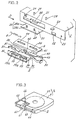
- FIG. 3 is a perspective view of a cartridge 6 proposed by the present applicant.
- the cartridge 6 comprises a flat shell 9 having accommodated therein a disk 60.
- the shell 9 has a side face having a slit 5 and an upper wall having a recessed portion 65.
- An aperture 63 is formed in the recessed portion 65 for exposing the disk 60.
- a shutter 61 for covering the aperture 63 is slidably disposed in the recessed portion 65 and fitted over the slit 5.
- the upper surface of the shutter 61 is positioned in the same plane as the upper surface of the shell 9.
- the shutter 61 is biased toward a closing direction by a torsion spring 66 within the shell 9 and is automatically closed even if opened inadvertently.
- a caved portion 64 is formed in the bottom wall of the cartridge 6.
- a slide member 3 is engageable in the caved portion 64 as will be described later. With the shutter 61 opened, the disk 60 within the shell 9 is partly exposed to record signals thereon or reproduce signals therefrom
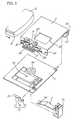
- FIG. 1 is an exploded perspective view of the recording or reproduction device for disks.
- a holder 2 is pivoted as at 25 at one end thereof to a chassis 1 provided with a pickup 72, and the cartridge 6 is inserted into the holder 2.
- the pickup 72 is movable toward or away from a turntable 73.
- a bracket 71 is attached to the pickup 72.
- a head lever 7 provided with a recording head 70 at an outer end thereof is pivoted at a base end thereof to the bracket 71.
- the head lever 7 is advanced by a lift mechanism (not shown) into the holder 2 through an opening 26 formed in an upper wall of the holder 2.
- the recording head 70 is brought into contact with the disk 60 within the cartridge 6 to record signals thereon as is known well.
- Release means 10 is provided at one corner of front end of the chassis 1. As will be described later, the release means 10 disengages the cartridge 6 from the holder 2 when the holder 2 as lowered is raised.
- the release means 10 is made from a metal plate by bending and in the form of an integral piece comprising a mount plate 13 in contact with the chassis 1, a support wall 12 projecting upward from the mount plate 13, and a release piece 11 extending from the upper end of the support wall 12 toward a cartridge unloading direction and slanting with respect to a plane in which the holder 2 moves pivotally.
- the release piece 11 is inclined upwardly outward and outwardly deflectable for deformation, with the support wall 12 serving as a base end portion.
- the release piece 11 has at a free end thereof an edge 14 so slanting as to give a width decreasing toward the cartridge unloading direction.
- the holder 2 has a bearing plate 27 inwardly projecting from the lower end of a side plate thereof.
- the bottom wall of the cartridge 6 is placed on the support plate 27.
- the cartridge 6 is restrained from backlashing upward or downward within the holder 2 by the bearing plate 27 and a protrusion 69 provided on the rear side of top wall of the holder 2.
- Extending outward from the lower end of one side wall of the holder 2 is a support plate 20 for supporting thereon the slide member 3.
- FIG. 2 is an exploded perspective view of the holder 2 and the slide member 3.
- the slide member 3 comprises an overlaid plate 34 having a vertical plate 35 extending upward from a side portion thereof. Slits 33 are formed in the overlaid plate 34. The slits 33 have fitted therein pins 28 projecting from the support plate 20, rendering the slide member 3 movable in the cartridge inserting and unloading directions.
- the pin 28 is a stepped pin comprising a small-diameter shank 28b and a flange 28a formed at the top end thereof.
- the slots 33 in the slide member 3 are each enlarged at one end to provide a large hole 33a having a slightly larger diameter than the flange 28a.
- the slide member 3 is mounted on the support plate 20 by positioning each large hole 33a in register with the flange 28a and thereafter moving the slide member 3 rearward.
- the flanges 28a prevent the slide member 3 from slipping off.
- a restraining piece 85 extends outward beyond an upper edge of an apertured portion 21 of the holder 2, and the vertical plate 35 of the slide member 3 is positioned inwardly of the restraining piece 85. The slide member 3 is prevented from backlashing outward by the restraining piece 85.
- a lock slide 4 is disposed above the slide member 3.
- the lock slide 4 is provided with slits 44, 44 having fitted therein pins 29, 29 projecting from the upper wall of the holder 2, whereby the lock slide 4 is made movable in the cartridge inserting and unloading directions.
- the slide member 3 of FIG. 2 is made from a metal plate by bending and is in the form of an integral piece comprising a tooth 31 projecting inward from the rear end of the vertical plate 35, a projection 32 extending upward from the approximate midportion of length of the vertical plate 35, a latch 30 positioned at the front end of the vertical plate 35 and having an inwardly projecting end, and a spring piece 37 extending rearward from the rear end of the vertical plate 35.
- the tooth 31 advances into the holder 2 to come into contact with an end face of the shutter 61, and the spring piece 37 fits to the shutter 61.
- the lock slide 4 is formed from a metal plate by bending and integrally has an engaging hook 40 extending from the lengthwise midportion thereof toward its front end, and a spring retainer 42 projecting outward from the approximate midportion of length thereof.
- the engaging hook 40 is elastically deformable downward and has a slope 43 at its outer end.
- a push plate 41 extends outward from the hook 40 in the vicinity of its base end.
- the holder 2 has the aperture 21 for the tooth 31 to move in and a hole 22 positioned forwardly of the aperture 21.
- the latch 30 fits into the hole 22, with the cartridge 6 inserted into the holder 2 completely.
- a lug 23 with which the hook 40 is engageable projects outward from the holder 2 above the hole 22.
- a hook 24 is provided on the holder 2 at the rear end thereof.
- the lock slide 4 is biased rearward by a tension spring 8 engaged with the hook 24 and the spring retainer 42 of the lock slide 4.
- the contact of the front ends of the slit portions 44 with the pins 29 restrains the lock slide 4 from moving rearward.
- the projection 32 of the slide member 3 bears on the rear side of the spring retainer 42 and is pulled along with the lock side 4 by the tension spring 8.
- the biasing force of the tension spring 8 is greater than the shutter biasing force of the torsion spring 66 inside the cartridge 6.
- the cartridge 6 is inserted into the holder 2 as pivotally moved upward. Signals are recorded on the disk or reproduced therefrom, with the cartridge 6 positioned as opposed to the chassis 1 by the downward pivotal movement of the holder 2.
- the head lever 7 will not be described below for convenience of description.
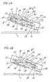
- FIGS. 4A, 4B are side elevations of the holder 2 in a raised position, FIG. 4A showing the holder before being loaded with the cartridge 6, FIG. 4B showing the holder with the cartridge 6 inserted therein completely.
- the engaging hook 40 is positioned to the rear of the lug 23.
- the latch 30 is positioned to the rear of the hole 22 in the holder 2 and deflected outward in contact with the side wall of the holder 2.
- FIGS. 5A, 5B are views showing the holder 2 of FIGS. 4A, 4B as it is seen from the direction A.
- FIGS. 6A, 6B are sectional views of the holder 2 of FIG. 4A as it is seen from the direction A.
- FIGS. 7A, 7B are sectional views of the holder 2 of FIG. 4B as it is seen from the direction A.
- the lock slide 4 and the tension spring 8 are not shown in FIGS. 6A, 6B, 7A, 7B.
- the engaging hook 40 is positioned inwardly of the release means 10, which will not interfere with the movement of the lock slide 4.
- the cartridge 6 is further pushed in.
- the shutter 61 which does not open further, pushes the tooth 31 of the slide member 3, advancing the slide member 3 to fit the latch 30 into the hole 22 as seen in FIG. 7A.
- the latch 30 inserted through the hole 22 lightly engages in the caved portion 64 of the cartridge 6, holding the cartridge 6 completely inserted in the holder.
- the projection 32 of the slide member 3 shown in FIG. 4A is in contact with the spring retainer 42 of the lock slide 4, so that the lock slide 4 advances against the tension spring 8 when the slide member 3 is pushed.
- the slope 43 of the engaging hook 40 in the state shown in FIG. 4A comes into contact with the lug 23, whereby the hook 40 is deformed by downward deflection.
- the engaging hook 40 restores itself elastically, coming into engagement with the lug 23 as shown in FIG. 4B.
- the lock slide 4 has its push plate 41 positioned above the release piece 11, with the cartridge completely inserted in the holder.
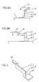
- FIG. 8A is a front view of the release means 10
- FIG. 8B is a right side elevation of the release means 10.
- the lock slide 4 When the lock slide 4 is moved down with the descent of the holder 2, the push plate 41 of the lock slide 4 comes into contact with the slanting edge 14 of the release piece 11 as shown in FIG. 5B and FIGS. 8A, 8B. Since the engaging hook 40 is restrained from deflecting upward and deforming by contact with the lug 23 (see FIG. 4B), the release piece 11 deflects outward as shown in FIG. 8A to permit passage of the push plate 41. The position to which the release piece 11 is outwardly deflected for deformation will be referred to as the deflected position.
- the release piece 11 is brought into contact with the slanting edge 14 for the following reason.
- the push plate 41 is likely to be positioned above the release piece 11 owing to an error in mounting the holder 2 or dimensional variations of components. If the slanting edge 14 is not formed as indicated by a chain line in FIG. 8B, the release piece 11 will not be deflected laterally, i.e., outward, for deformation merely by being depressed at its upper end by the push plate 41 when the holder 2 is lowered. It is therefore likely that the push plate 41 will be unable to move past the release piece 11.
- the push plate 41 lowers while pushing the slanting edge 14, even if the position where the holder is mounted somewhat differs from device to device.
- the release piece 11 accurately escapes sideways. This enables the push plate 41 to move past the release piece 11 reliably.
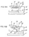
- FIGS. 10A, 10B are enlarged side elevations of the release means 10 and the engaging hook 40.
- the release piece 11 restores itself elastically to return to the original position, i.e., to a standby position.
- the holder 2 is pivotally moved upward when the cartridge 6 is to be unloaded from the holder 2.
- the push plate 41 of the lock slide 4 comes into contact with the lower end of the release piece 11 as seen in FIG. 10B.
- the release piece 11 is opposed to a plane in which the holder 2 is pivotally moved upward and downward and is therefore not readily deflectable upward or downward. Accordingly, the release piece 11 deflects the engaging hook 40 downward for deformation by contact with the push plate 40, releasing the hook 40 form engagement with the lug 23.
- the lock slide 4 is moved in the cartridge unloading direction by the tension spring 8.
- the lock slide 4 pushes the projection 32 of the slide member 3 rearward as shown in FIG. 4A to unload the cartridge 6.
- the release piece 11 has a length extending generally in parallel to the cartridge inserting-unloading direction and is therefore greatly deformable by deflecting laterally, i.e., outward, about its base end portion. This makes it possible to provide a great allowance for the engagement of the lock slide 4 with the releases piece. Accordingly, the lock slide 4 can be released from engagement with the holder 2 with good stability.
- the space for the provision of the release piece 11 needs only to have a lateral width corresponding to the amount of lateral deflective deformation thereof permitting the passage of the lock slide 4, so that the lateral width can be shortened.
- the release piece 11 of the release means 10 needs only to be such that it is outwardly deflectable for deformation with the support wall 12 serving as its base end portion. As shown in FIG. 9, therefore, the release piece 11 may extend straight rearward from the support wall 12, with its forward end only inclined.
- the lock slide 4 comes into contact with the release piece 11, deflecting the release piece 11 laterally, i.e., outward, for deformation.
- the release piece 11 permits passage of the lock slide 4 and elastically restores itself to return to the original position upon passage of the lock slide 4.
- the release piece 11 has a large length extending in the cartridge inserting-unloading direction and is therefore greatly deformable by deflecting outward about its base end portion, so that the allowance for the engagement of the lock slide 4 with the release piece can be made great. This renders the lock slide 4 releasable from engagement with the holder 2 with good stability.
- the lateral width of the space for the provision of the release piece 11 needs only to correspond to the amount of lateral deflective deformation thereof permitting the passage of the lock slide 4.
- the lateral width of the space for the installation of the release piece 11 in the prior art must not be smaller than the length of the release piece 11 as shown in FIG. 12. Accordingly, the lateral width can be made smaller than conventionally.
Landscapes
- Feeding And Guiding Record Carriers (AREA)
- Pile Receivers (AREA)
Abstract
Description
Accordingly, the
Claims (3)
- A signal recording or reproduction device for disks which comprises a holder (2) pivoted at a base end thereof to a chassis (1) and pivotally movable for accommodating therein a cartridge (6) enclosing a disk (60) therein, a lock slide (4) mounted on the holder (2) and movable in cartridge inserting and unloading directions, the lock slide (4) being movable with the insertion of the cartridge (6) to engage with the holder (2), and release means (10) for disengaging the lock slide (4) from the holder (2) when the holder (2) is pivotally moved upward from a lowered position, the signal recording or reproducing device being characterized in that:the release means (10) has a release piece (11) slanting with respect to the plane of pivotal movement of the holder (2) and attached at a base end thereof to the chassis (1), the release piece (11) being elastically deformable outward and extending from the base end approximately in parallel to the cartridge inserting-unloading directions,the release piece (11) being movable between a deflected position to which the release piece is elastically deformed outward by being pushed by the lock slide (4) when the holder (2) is lowered to permit passage of the lock slide (4) and a standby position in which the release piece (11) restores itself elastically and disengages the lock slide (4) from the holder (2) by coming into contact with the lock slide (4) when the holder (2) is pivotally moved upward from the lowered position.
- A signal recording or reproduction device for disks according to claim 1 wherein the holder (2) is provided with a lug (23) for the lock slide (4) to engage with, and when the holder (2) is pivotally moved down, the lock slide (4) comes into contact with the release piece (11) while in engagement with the lug (23) and is restrained from deforming by deflection.
- A signal recording or reproduction device for disks according to claim 1 wherein the portion of the release piece (11) to be brought into contact with the lock slide (4) is a slanting edge (14) so inclined that the release piece (11) has a width decreasing toward the cartridge unloading direction.
Applications Claiming Priority (3)
| Application Number | Priority Date | Filing Date | Title |
|---|---|---|---|
| JP19529499 | 1999-07-09 | ||
| JP19529499A JP3389534B2 (en) | 1999-07-09 | 1999-07-09 | Signal recording / reproducing device for disk |
| PCT/JP2000/004506 WO2001004891A1 (en) | 1999-07-09 | 2000-07-05 | Device for recording or reproducing signal on or from disk |
Publications (2)
| Publication Number | Publication Date |
|---|---|
| EP1202268A1 true EP1202268A1 (en) | 2002-05-02 |
| EP1202268A4 EP1202268A4 (en) | 2004-09-08 |
Family
ID=16338773
Family Applications (1)
| Application Number | Title | Priority Date | Filing Date |
|---|---|---|---|
| EP00944299A Withdrawn EP1202268A4 (en) | 1999-07-09 | 2000-07-05 | Device for recording or reproducing signal on or from disk |
Country Status (6)
| Country | Link |
|---|---|
| US (1) | US6829773B1 (en) |
| EP (1) | EP1202268A4 (en) |
| JP (1) | JP3389534B2 (en) |
| KR (1) | KR100628403B1 (en) |
| CN (1) | CN1174408C (en) |
| WO (1) | WO2001004891A1 (en) |
Families Citing this family (1)
| Publication number | Priority date | Publication date | Assignee | Title |
|---|---|---|---|---|
| JP2014071909A (en) * | 2012-09-27 | 2014-04-21 | Sony Corp | Cartridge drive apparatus |
Family Cites Families (8)
| Publication number | Priority date | Publication date | Assignee | Title |
|---|---|---|---|---|
| DE3415412A1 (en) * | 1983-04-25 | 1984-12-20 | Canon K.K., Tokio/Tokyo | Recording or reproducing device |
| DE69319660T2 (en) * | 1992-05-22 | 1998-11-19 | Sony Corp | Disk cassette charger |
| JP3533681B2 (en) * | 1993-09-20 | 2004-05-31 | ソニー株式会社 | Eject mechanism for cartridge |
| JP3425336B2 (en) * | 1997-09-29 | 2003-07-14 | 松下電器産業株式会社 | Disk unit |
| JP3425338B2 (en) * | 1997-10-03 | 2003-07-14 | 松下電器産業株式会社 | Disk unit |
| JP3000003B1 (en) * | 1998-10-08 | 2000-01-17 | 三洋電機株式会社 | Recording / reproducing apparatus for disc stored in cartridge |
| JP4063995B2 (en) * | 1999-03-01 | 2008-03-19 | 松下電器産業株式会社 | Cartridge eject device |
| JP3427006B2 (en) | 1999-03-19 | 2003-07-14 | 三洋電機株式会社 | Apparatus for recording or reproducing signals on disk and method for inserting and ejecting cartridges from the apparatus |
-
1999
- 1999-07-09 JP JP19529499A patent/JP3389534B2/en not_active Expired - Fee Related
-
2000
- 2000-07-05 CN CNB008100624A patent/CN1174408C/en not_active Expired - Fee Related
- 2000-07-05 EP EP00944299A patent/EP1202268A4/en not_active Withdrawn
- 2000-07-05 KR KR1020027000229A patent/KR100628403B1/en not_active Expired - Fee Related
- 2000-07-05 US US09/926,458 patent/US6829773B1/en not_active Expired - Fee Related
- 2000-07-05 WO PCT/JP2000/004506 patent/WO2001004891A1/en not_active Ceased
Also Published As
| Publication number | Publication date |
|---|---|
| JP3389534B2 (en) | 2003-03-24 |
| EP1202268A4 (en) | 2004-09-08 |
| KR100628403B1 (en) | 2006-09-26 |
| CN1174408C (en) | 2004-11-03 |
| WO2001004891A1 (en) | 2001-01-18 |
| US6829773B1 (en) | 2004-12-07 |
| CN1360717A (en) | 2002-07-24 |
| KR20030009275A (en) | 2003-01-29 |
| JP2001023274A (en) | 2001-01-26 |
Similar Documents
| Publication | Publication Date | Title |
|---|---|---|
| US6052256A (en) | Recording device for a removable disk cartridge wherein a chassis is movable with respect to an inner holder | |
| US6802069B1 (en) | Device for recording or reproducing signals on disk and method of inserting and extracting cartridge for the device | |
| US6829773B1 (en) | Device for recording or reproducing signal on or from disk with a releasing mechanism | |
| EP1227488B1 (en) | Cartridge containing disk and device for recording or reproducing signal on or from the disk | |
| US6542329B2 (en) | Holder mounting structure | |
| US6829774B2 (en) | Cartridge storage device | |
| US6807669B2 (en) | Device for accommodating cartridge storage device and disk recording or playback apparatus | |
| EP1227490B1 (en) | Cartridge in which disk is stored | |
| JP3427006B2 (en) | Apparatus for recording or reproducing signals on disk and method for inserting and ejecting cartridges from the apparatus | |
| US5999363A (en) | Cassette housing having cassette stoppers to prevent mis-insertion | |
| KR100243165B1 (en) | Disk cartridge deck | |
| JP2002245703A (en) | Disk recording or playback device | |
| KR100243166B1 (en) | Disk cartridge deck | |
| JP2003045141A (en) | Disc case | |
| JP2002358755A (en) | Magnetic tape cartridge | |
| JPH0626075B2 (en) | Locking device for magnetic recording medium in magnetic recording / reproducing device | |
| JPWO2001004899A1 (en) | Cartridge containing a disc and a device for recording or reproducing signals onto or from said disc | |
| JPH0473227B2 (en) | ||
| JP2007087544A (en) | Disk device | |
| JPH01113949A (en) | Cassette loading device | |
| JPH07302459A (en) | Disk device | |
| JPH0732723U (en) | Magnetic recording / reproducing device | |
| JPH07307052A (en) | Optical disk device | |
| JP2000207804A (en) | Disk unit |
Legal Events
| Date | Code | Title | Description |
|---|---|---|---|
| PUAI | Public reference made under article 153(3) epc to a published international application that has entered the european phase |
Free format text: ORIGINAL CODE: 0009012 |
|
| 17P | Request for examination filed |
Effective date: 20020131 |
|
| AK | Designated contracting states |
Kind code of ref document: A1 Designated state(s): AT BE CH CY DE DK ES FI FR GB GR IE IT LI LU MC NL PT SE |
|
| RBV | Designated contracting states (corrected) |
Designated state(s): DE FR GB |
|
| A4 | Supplementary search report drawn up and despatched |
Effective date: 20040728 |
|
| 17Q | First examination report despatched |
Effective date: 20050414 |
|
| GRAP | Despatch of communication of intention to grant a patent |
Free format text: ORIGINAL CODE: EPIDOSNIGR1 |
|
| STAA | Information on the status of an ep patent application or granted ep patent |
Free format text: STATUS: THE APPLICATION IS DEEMED TO BE WITHDRAWN |
|
| 18D | Application deemed to be withdrawn |
Effective date: 20060905 |