EP1202104A1 - Head mountable display device - Google Patents
Head mountable display device Download PDFInfo
- Publication number
- EP1202104A1 EP1202104A1 EP00949950A EP00949950A EP1202104A1 EP 1202104 A1 EP1202104 A1 EP 1202104A1 EP 00949950 A EP00949950 A EP 00949950A EP 00949950 A EP00949950 A EP 00949950A EP 1202104 A1 EP1202104 A1 EP 1202104A1
- Authority
- EP
- European Patent Office
- Prior art keywords
- arm
- head
- image display
- image
- viewer
- Prior art date
- Legal status (The legal status is an assumption and is not a legal conclusion. Google has not performed a legal analysis and makes no representation as to the accuracy of the status listed.)
- Withdrawn
Links
- 239000000758 substrate Substances 0.000 claims abstract description 18
- 210000003128 head Anatomy 0.000 claims description 49
- 230000003287 optical effect Effects 0.000 claims description 22
- 150000001875 compounds Chemical class 0.000 abstract description 9
- 230000001681 protective effect Effects 0.000 description 14
- 239000002184 metal Substances 0.000 description 8
- 238000005286 illumination Methods 0.000 description 7
- 230000000007 visual effect Effects 0.000 description 6
- 238000004891 communication Methods 0.000 description 5
- 230000007613 environmental effect Effects 0.000 description 5
- NIXOWILDQLNWCW-UHFFFAOYSA-N acrylic acid group Chemical group C(C=C)(=O)O NIXOWILDQLNWCW-UHFFFAOYSA-N 0.000 description 3
- 229920001971 elastomer Polymers 0.000 description 3
- 230000005236 sound signal Effects 0.000 description 3
- 238000013459 approach Methods 0.000 description 2
- 230000003247 decreasing effect Effects 0.000 description 2
- 238000011161 development Methods 0.000 description 2
- 210000000887 face Anatomy 0.000 description 2
- 239000005060 rubber Substances 0.000 description 2
- 210000000216 zygoma Anatomy 0.000 description 2
- 238000005452 bending Methods 0.000 description 1
- 210000000988 bone and bone Anatomy 0.000 description 1
- 239000004020 conductor Substances 0.000 description 1
- 230000000694 effects Effects 0.000 description 1
- 239000000806 elastomer Substances 0.000 description 1
- 229920001821 foam rubber Polymers 0.000 description 1
- 238000007689 inspection Methods 0.000 description 1
- 238000012423 maintenance Methods 0.000 description 1
- 239000000463 material Substances 0.000 description 1
- 238000000034 method Methods 0.000 description 1
- 230000005855 radiation Effects 0.000 description 1
- 210000001525 retina Anatomy 0.000 description 1
- 229920003051 synthetic elastomer Polymers 0.000 description 1
- 239000005061 synthetic rubber Substances 0.000 description 1
- XLYOFNOQVPJJNP-UHFFFAOYSA-N water Substances O XLYOFNOQVPJJNP-UHFFFAOYSA-N 0.000 description 1
Images


Classifications
-
- G—PHYSICS
- G02—OPTICS
- G02B—OPTICAL ELEMENTS, SYSTEMS OR APPARATUS
- G02B27/00—Optical systems or apparatus not provided for by any of the groups G02B1/00 - G02B26/00, G02B30/00
- G02B27/01—Head-up displays
- G02B27/017—Head mounted
- G02B27/0176—Head mounted characterised by mechanical features
-
- G—PHYSICS
- G02—OPTICS
- G02B—OPTICAL ELEMENTS, SYSTEMS OR APPARATUS
- G02B27/00—Optical systems or apparatus not provided for by any of the groups G02B1/00 - G02B26/00, G02B30/00
- G02B27/01—Head-up displays
- G02B27/017—Head mounted
- G02B27/0172—Head mounted characterised by optical features
-
- G—PHYSICS
- G02—OPTICS
- G02B—OPTICAL ELEMENTS, SYSTEMS OR APPARATUS
- G02B27/00—Optical systems or apparatus not provided for by any of the groups G02B1/00 - G02B26/00, G02B30/00
- G02B27/01—Head-up displays
- G02B27/017—Head mounted
- G02B2027/0178—Eyeglass type
Definitions
- the present invention relates to a head-mounted display device having an optical system that projects an image, which is produced by an image display means, on at least one of the observer's retinas.
- HMD head-mounted display
- various types of monocular head-mounted display devices have been proposed in order to view an output image including an image represented by data sent from a personal computer with one eye.
- This type of display device is used to manage articles or maintain and inspect machines by a user who can view a screen image, which is produced by a personal computer and transmitted by a display device, with one eye, and observe an ambient environmental condition with the other eye at the same time.
- Japanese Unexamined Patent Application Publication No. 10(1998)-74051 has disclosed a head-mounted display device that is a monocular display device shared by the left eye and the right eye.
- Japanese Unexamined Patent Application Publication No. 10(1998)-123455 has disclosed a head-mounted display device that has an optical element fixed to the front end of an arm that extends forwards from one lateral side of an observer. Even if the optical element or arm collides with an obstacle, the display device is prevented from being broken.
- a head-mounted display device disclosed in Japanese Unexamined Patent Application Publication No. 10(1998)-75408 that holds a monocular viewing arm and an optical element and can be worn on the head readily and quickly owing to the elasticity of a supporting block.
- Japanese Unexamined Patent Application Publication No. 10(1998)-39784 has disclosed a head-mounted image display device that is of a monocular type and enables an observer to freely change the direction of a virtual image relative to the observer.
- Japanese Unexamined Patent Application Publication No. 8(1996)-305298 has disclosed a head-mounted display device that will not block an observer's front visual field.
- a display device disclosed in Japanese Unexamined Patent Publication No. 8(1996)-320453 is a monocular head-mounted display device whose display unit can be attached to or detached from a position at which an image is projected exclusively to one of the right and left eyes or a position at which an image is projected exclusively to the other eye.
- the position of the display unit is limited to an upward position. This is inconvenient for a user to view an image. Moreover, the user has little freedom in selecting a direction of viewing. Thus, the display devices are not user-friendly.
- An object of the present invention is to provide a head-mounted display device that is compact, can be worn on the head readily, and enables a user to view a display screen image and observe an ambient environmental condition at the same time. Moreover, an earphone can be handled readily. The head-mounted display device is thus user-friendly.
- the present invention provides a head-mounted image display device consisting mainly of an image display means, an optical system, a casing block, and a supporting block.
- the optical system projects an image, which is produced by the image display means, and/or an image of an ambient outside world on at least one of the observer's eyes.
- the casing block accommodates the image display means and optical system, and holds the image display means and optical system at a position near the observer's head at which an image is viewed.
- the supporting block supports the casing block on the head.
- the casing block includes an arm member and a viewer member.
- the arm is borne by the supporting block.
- the viewer is borne by the arm and has the image display means and optical system incorporated therein. The portion of the arm adjoining the viewer is narrowed.
- the supporting block is mounted on the head in order to wear the casing block on the head.
- An observer views an image and/or an ambient outside world with at least one of his/her eyes through the optical system incorporated in the viewer of the casing block.
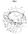
- Fig. 1 is a perspective view showing a monocular HMD that is a head-mounted image display device in accordance with the embodiment of the present invention, wherein the monocular HMD is worn on the head.
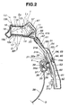
- Fig. 2 is a cross sectional view of the monocular HMD.
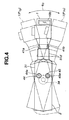
- Fig. 3 is a plan view of the monocular HMD which is worn on the head and whose viewer is turned in a horizontal direction and whose arm is rotated therein.
- Fig. 4 is a side view showing the monocular HMD whose arm is rotated in a vertical direction.
- Fig. 5 is a development showing a compound circuit board unit that is incorporated in the viewer and the arm alike.
- the monocular HMD in accordance with the present embodiment is a display device used to manage articles or maintain and inspect machines.
- the display device is worn on the observer's head, whereby the observer views with his/her right or left eye a screen image, which is produced by a personal computer and transmitted by a viewer that is a display unit, together with a see-through screen image that is an image of an ambient outside world.
- the monocular HMD consists mainly of, as shown in Fig. 1, a viewer 1, an arm 2, and a headband 3.
- the viewer 1 is one member of a casing block in which a single image display means and an optical system are incorporated.
- the arm 2 is the other member of the casing block in which an input circuit, a main control circuit, and selection switches are incorporated and an earphone is stowed.
- the headband 3 is a supporting block that supports the arm 2 and is worn on the observer's head.
- An image signal and an audio signal sent from a personal computer (not shown) are received by the input circuit incorporated in the HMD via a HMD controller (not shown). Consequently, an image or sounds are reproduced.
- a compound circuit board unit 51 including circuits that process an image signal and an audio signal received by the monocular HMD is incorporated in the viewer 1 and arm 2 alike.
- the compound circuit board unit 51 consists of, as shown in Fig. 5, an input circuit board 52 that is a rigid substrate, a main control circuit board 54 that is a rigid substrate, a drive circuit board 56 that is a rigid substrate, an LCD substrate 57 that is a rigid substrate, a flexible printed-circuit board (hereinafter FPC) 53, and an FPC 55.
- the FPC 53 links the input circuit board 52 and main control circuit board 54.
- the FPC 55 links the main control circuit board 54, LCD drive circuit board 56, and LCD substrate 57.
- a CPU 63 responsible for control of the whole HMD, and selection switches 64 and 65 to be used to change screen image displayed states are mounted on the main control circuit board 54.
- An LCD drive circuit IC 66 is mounted on the drive circuit board 56.
- An LCD 67 that is a reflective display element serving as an image display means, an illumination LED 12, and a connector 68 through which a microphone 20 is connected are mounted on the LCD substrate 57.
- the viewer 1 consists mainly of a main viewer unit and a prism unit.
- the main viewer unit includes, as shown in Fig. 2 and Fig. 3, a viewer body 11, the drive circuit board (rigid substrate) 56, the LCD substrate (rigid substrate) 57, an illumination prism 13, two light source LEDs 12, and the microphone 20.
- the viewer body 11 is borne by the arm 2 using hinge pins 41a and 41b so that the viewer body 11 can pivot in horizontal directions ⁇ 1.
- the drive circuit board 56 and LCD substrate 57 are members incorporated in the viewer body 11 and included in the compound circuit board unit 51.
- the LCD drive circuit IC 66 is mounted on the drive circuit board 56, and the LCD 67 serving as a reflective display element (display means) is mounted on the LCD substrate 57.
- the illumination prism 13 is opposed to the face of the LCD 67.
- the two light source LEDs 12 are LEDs mounted on an LED substrate that is not shown, and placed above the illumination prism 13.
- the viewer body 11 is made of a metal that little undergoes a time-passing change or deforms due to temperature and that is useful in preventing leakage light. A material that hardly distorts due to a humid or temperature change is adopted for the illumination prism 13 in order to prevent a resistive distortion. Moreover, the LCD drive circuit IC 66 is located near the LCD 67 in the viewer body 11, thus suppressing generation of radiation noise to the greatest possible extent.
- the prism unit consists mainly of a prism holding metal 16, a free-shape prism (free-form surface prism) 14, a see-through prism 15, an eyepiece-side acrylic panel 17, an objective-side acrylic panel 18, and a protective cover 19.
- the prism holding metal 16 is realized with a sheet metal and fixed to the viewer body 11.
- the free-shape prism 14 is included in an optical system and fixed to or borne by the holding metal 16.
- the see-through prism 15 is included in the optical system and has the see-through surface thereof bonded to the prism 14.
- the eyepiece-side and objective-side acrylic panels 17 and 18 are protective transparent panels finished to repel water and fixed to or borne by the holding metal 16 or viewer body 11.
- the protective cover 19 is attached to the periphery of the holding metal 16 or viewer body 11.
- the protective cover 19 is made of a synthetic rubber (elastomer) that can deform elastically, and has an inner opening 19a, an outer opening 19b, and a nose pad portion 19c.
- the protective cover 19 is elastically deformed to be attached to the holding metal 16 or viewer body 11.
- the protective cover 19 thus intercepts extraneous light other than light coming through the see-through prism, and keeps the prism unit waterproof and dustproof.
- the protective cover 19 is freely attachable or detachable. Thus, another protective cover devoid of the outer opening 19b may be made available.
- the protective cover 19 is replaced with the protective cover devoid of the outer opening 19b, the head-mounted image display device becomes usable in a mode in which a see-through screen image cannot be viewed.
- the protective cover 19 may be made stationary.
- an extraneous light intercepting member may be freely detachably attached to the outer opening 19b of the protective cover 19 using a mechanical or manual means so that the same effect can be obtained.
- the viewer 1 can be turned in directions ⁇ 1 (see Fig. 3) with the hinge pins 41a and 41b, which will be described later, as a fulcrum.
- the nose pad portion 19c of the protective cover 19 contacts the observer's nose 87.
- the prism unit will therefore not approach the nose too closely with a distance shorter than a predetermined distance between them.
- the arm 2 consists mainly of the hinge pins 41a and 41b, an arm body 31, the main control circuit board 54, the input circuit board 52, control buttons 44 and 45, and a joint 21.
- the hinge pins 41a and 41b support the viewer 1 so that the viewer 1 can pivot in the directions ⁇ 1.
- the arm body 31 has such a curvature as to lie along the periphery of the head.
- the main control circuit board 54 and input circuit board 52 are members incorporated in the arm body 31.
- the CPU 63 responsible for control of the whole device and the selection switches 64 and 65 used to change screen image displayed states are mounted on the main control circuit board 54, and the connector 61 and input circuit IC 62 are mounted on the input circuit board 52.
- the control buttons 44 and 45 are operated in order to press the selection switches 64 and 65 respectively.
- the joint 21 links the arm 2 and the headband 3.
- the arm 2 has a narrowed portion 31d, which is narrowed in the width direction (vertical direction) thereof as shown in Fig. 4, formed around the hinge pins 41a and 41b adjacently to the viewer 1.
- the narrowed portion 31d lessens limitation of the viewing eye's visual field, which extends in the outside world, by the arm 2.
- a dustproof cover 42 made of a rubber that can elastically deform and capable of freely bending is attached to the joint between the arm 2 which includes the hinge pins 41a and 41b and the viewer 1.
- the dustproof cover 42 also fills the role of keeping the joint waterproof.
- a main cable 7 protected with a bushing 8 and an earphone cord 10 are extended from the rear end of the arm body 31 (opposite to the distal end thereof adjoining the viewer).
- the main cable 7 and earphone cord 10 extend backwards from above the ear 84.
- the main cable 7 is a serial communication signal cable that extends from the HMD controller (not shown).
- the main cable 7 enables fast communication, and has the number of conductors contained therein decreased to exhibit excellent flexibility. So a user wearing the monocular HMD on the head will not be annoyed by the main cable 7.
- a communication signal sent from a personal computer to the HMD controller is a parallel signal. The communication signal is converted into a serial communication signal by the HMD controller, and transferred to the monocular HMD over the main cable 7.
- a monophonic earphone of an ear-embedded type is adopted so that sounds generated in the outside world can be clearly distinguished from sounds generated by the personal computer.
- the earphone 9 can be mounted or stowed in an earphone mount 31c that is a concave part of the surface of the rear portion of the arm body 31 which faces inwards, that is, faces the head. With the earphone 9 stowed, the sounding opening of the earphone 9 faces the head. Even in this state, a user can hear sounds.
- the joint 21 consists mainly of a joint body 32 and a ball support 33 that is divided into two portions.
- the joint body 32 includes a portion, which is engaged with a sliding groove 31a of the arm body 31 so that it can slide freely, and a holder 32a that holds the ball support 33.
- the arm 2 slides in directions D1
- the arm 2 slides along the sliding groove 31a while causing the holder 32a of the joint body to escape to an escape 31b.
- the arm 2 slides to trace a large arc that has the center P0 of the head 81 as a center.
- This sliding movement may be a straight sliding movement made back and force relative to the head.
- the ball support 33 divided into two portions clamps a ball 34 fixed to a right face pad member 4 that will be described later.
- the ball support 33 holds the ball 34 so that the ball 34 can rotate with appropriate frictional holding force exerted.
- the ball support 33 is fixed to or borne by the joint body 32.
- control buttons 44 and 45 that are operated in order to press the selection switches 64 and 65 are lined vertically on the surface of the arm body 31 that faces outside.
- the position of the control buttons 44 and 45 is near the position of the ball support 33 and close to the viewer 1. Even when the arm 2 is slid to the rear end, the control buttons 44 and 45 will not move backwards farther than a line linking the center P0 of the head and the ball 34.
- the control buttons 44 and 45 have different shapes.
- the control button 44 has a projection 44a in the center thereof, while the control button 45 has a concave part 45a in the center thereof. Since the control buttons 44 and 45 have different shapes, when the control buttons 44 and 45 are operated in order to press the selection switches 64 and 65 to thus change screen image displayed states, whichever of the control buttons is pushed can be reliably recognized. Thus, an incorrect operation is prevented.
- the screen image displayed states to be switched include a state in which a screen image is displayed on the LCD 67 while being reversed (180° rotated display), a state in which a screen image is displayed with the luminance of illumination light changed (with the brightness of a display screen image changed), a state in which a selected screen image displayed state is reset, and a state in which a screen image is displayed at an adjusted position on the screen (a finely adjusted position at which the screen image is easier to view with the eye).
- the image displayed states are sequentially changed stepwise by repeatedly pressing the selection switch 65.
- the circuit board unit 51 is incorporated in the viewer 1 and arm 2 alike. Within the viewer 1, the circuit board 51 is placed in a proper posture while having the FPC 55a bent so that the rigid LCD substrate 57 will be orthogonal to the LCD drive circuit board 56. In particular, within the arm 22, the FPC 53 and FPC 55 are bent in order to place the input circuit board 52 and main control circuit board 54, which are rigid substrates, in a posture conformable to the curvature of the outline of the arm 2. According to a variant, the FPCs 55a, 55, and 53 are replaced with loose cables or flexible cables that have cuts made thereon so as to be able to bend freely.
- the headband 3 consists mainly of, as shown in Fig. 1 and Fig. 3, a thin-sheet band 38 and right and left face pad members 4 and 5.
- the band 38 can elastically deform to trace an arc in conformity with the shape of the observer's head 81.
- the right and left face pad members 4 and 5 are located by a distance X0 ahead of a line linking the ear 84 and the center of the head P0.
- the right face pad member 4 is fixed to both ends of the band 38.
- the right face pad member 4 consists mainly of a pad 37, a pad holding panel 36, a ball 34, and a ball holding panel 35.
- the pad 37 is made of a foam rubber (sponge) that can come into contact with the cheekbone 86 or superior ocular bone.
- the pad holding panel 36 holds the pad 37.
- the ball 34 has a spherical shape and includes a screw 34a.
- the ball 34 is fixed to the ball holding panel 35 with a nut 39 between them.
- the band 38 is held clamped by the pad holding panel 36 and ball holding panel 35.
- the ball 34 is used to bear the joint 21 of the arm 2 so that the arm 2 can rotate with predetermined frictional holding force exerted.
- the pad member 4 may be realized with a highly frictional member, or may have a sawtoothed surface as a surface that comes into contact with the head so that the pad member 4 will not shift on the head.
- the left face pad member 5 has the same structure as the right face pad member 4 does but is devoid of the ball 34.
- the arm 1 bears the viewer 1 so that the viewer 1 can pivot on the hinge pins 41a and 41b.
- the viewer 1 can therefore move in the lateral directions ⁇ 1 between a position P1a and a position P1b (see Fig. 3).
- the arm 2 is borne by the ball 34 included in the right face pad member 4 via the joint 21 so that the arm 2 can rotate. Therefore, the arm 2 can rotate in lateral directions ⁇ 2 (see Fig. 3) and in vertical directions ⁇ 3 (see Fig. 4). This allows the viewer 1 to move from a position P1a to a position P1c and from a position P1g to a position P1h, simultaneously.
- the arm 2 is borne by the right face pad member 4 via the joint body 32 so that the arm 2 can slide in the directions D1 (see Fig. 3). This allows the viewer 1 to move from a position P1d to a position P1e.
- the headband 3 is worn on the head 81 as shown in Fig. 1.
- the earphone 9 is inserted into the ear 84.
- the controller is operated to transmit a video signal to the monocular HMD over the cable 7.
- An image is transmitted by the LCD 67 included in the viewer 1 according to the received video signal.
- Reflected light L1 of the displayed image passes through the illumination prism 13 and falls on the prism 14. The light is then converged at an eye point (EP) on the observer's right eye 82.
- EP eye point
- Sounds represented by an audio signal are heard through the earphone 9. Even when the earphone 9 is left stowed or mounted in the earphone mount 31c of the arm 2, since the opening of the earphone 9 faces the ear, sounds can be heard.
- the arm 2 can slide in the directions D1 relative to the right face pad 4. Moreover, the arm 2 can rotate in the directions ⁇ 2 and directions ⁇ 3.
- the viewer 1 can pivot in the directions ⁇ 1 on the hinge pins 41a and 41b included in the arm 2. A position or posture at or in which the viewer 1 is set in order to view an image can therefore be adjusted to a desired position or posture, which is suitable for a work situation, relative to the right eye 82.
- the control buttons 44 and 45 are operated in order to shift the position of the screen image displayed on the LCD 67.
- the viewer 1 is, as mentioned above, rotated in the lateral directions ⁇ 1 or the arm 2 is turned in the lateral directions ⁇ 2 or the vertical directions ⁇ 3. If the distance in the direction of a ray axis O from the viewer 1 is improper, the arm 2 is turned as mentioned above and then slid in the directions D1 to lie at a proper position.
- the headband 3 having the arm 2 and viewer 1 fixed thereto is reversed laterally and then worn on the head.
- the viewing eye can be readily changed from the right eye 82 to the left eye 83.
- This is attributable to the fact that the right and left face pad members 4 and 5 share the same structure and the ray axis O of light projected by the viewer 1 extends to cross a line linking the center of the right face pad member 4 (center of the ball 34) and the center of the left face pad member 5 or cross a point near the line.
- the selection switch 65 before viewing an image is started, the selection switch 65 must be pressed (by operating the control button 45) with the selection switch 64 held down (by operating the control button 44). Thus, a screen image displayed by the viewer 1 must be reversed (rotated 180° by changing vertical and lateral positions). Otherwise, the selection switch 64 or 65 is pressed in order to reverse a screen image displayed by the viewer 1.
- the position or posture at or in which the viewer 1 is set in order to view an image can be, as mentioned above, adjusted by rotating and sliding the arm 2 and turning the viewer 1. Moreover, owing to the nose pad portion 19c, the viewer 1 will neither come into contact with the nose 87 nor approach the viewer 1 too closely with a distance shorter than a predetermined distance between them.
- the right and left face pad members 4 and 5 share the same structure.
- the ball 34 may be detached together with the arm 2 and joint 21 by removing the nut 39, and then attached to the left face pad member 5. Consequently, the viewing eye may be changed from the right eye to the left eye or vice versa. Even in this case, it is necessary to reverse a displayed state of a screen image.
- the ball 34 may be detached together with the arm 2 and joint 21 by temporarily removing the nut 39, and attached to a dedicated adapter.
- the ball 34 can be attached not only to the headband 3 but also to a head holding means such as a helmet or a cap or the like.
- the headband 3, arm 2, and viewer 1 are assembled as one structure. Therefore, the monocular HMD can be worn comfortably and handled with improved ease. Moreover, the right and left face pad members 4 and 5 of the headband 3 are brought into contact with any positions on the cheekbone. A region on which the HMD is worn can be selected relatively freely. A difference in a region on which the HMD is worn between one individual to another can therefore be absorbed.
- the compound circuit board unit 51 composed of a plurality of rigid circuit boards and a plurality of FPCs
- a posture in which the circuit board unit 51 is placed can be determined freely in conformity with the curvatures exhibited by the outlines of the bodies of the viewer 1 and arm 2.
- the monocular HMD, or in particular, the arm thereof can be designed compactly.
- shapes determined with priority given to the best way of functioning the viewer and arm can be adopted as the shapes of the viewer 1 and arm 2.
- the arm 2 since the arm 2 has the narrowed portion 31d as mentioned above, although the observer's visual field is narrowed by the viewer 1 and arm 2, part of the visual field is left intact owing to the narrowed portion. An ambient environmental condition on the side of a viewing eye can therefore be recognized with the viewing eye.
- the monocular HMD is worn on the head 81, the headband is not present on the superior region of the head 81. Consequently, a helmet can be worn together with the monocular HMD. This is helpful in performing work such as maintenance and inspection of a machine.
- control buttons 44 and 45 are located near the ball support 33 and closely to the viewer 1. This leads to improved ease of operation. Moreover, a user who operates the control buttons has only a little pain in the head. Furthermore, the control buttons 44 and 45 are different from each other in shapes. Therefore, even when image displayed states are changed, or more particularly, even when a viewing eye is changed from the right eye to the left eye by laterally reversing the headband 3, pressing an incorrect switch can be prevented.
- the plurality of control buttons that are operated in order to press the switches and that have different shapes is arranged on the arm 2. Operating an incorrect control button after a viewing eye is changed from the right eye to the left eye can be prevented. This results in improved operability.
- the main cable 7 is extended backwards behind the ear 84, and can therefore be readily routed to the back. Consequently, when a viewing eye is changed from the right eye to the left eye by laterally reversing the headband, or when the control buttons 44 and 45 are operated in order to change image displayed states, the main cable 7 will not be annoying.
- the control buttons can be operated easily. This results in improved maneuverability.
- the earphone 9 is mounted on the earphone mount 31c of the arm 1, when the monocular HMD is carried, the earphone cord 10 will not get tangled. Moreover, since the earphone 9 is of an ear embedded type, an external emergency sound or the like can be readily identified. Moreover, even when the earphone 9 is left mounted on the earphone mount 31c, since the sounding opening of the earphone 9 faces the head, sounds are audible.
- control buttons 44 and 45 can be arranged along the extension of the ball support 33 closely to the posterior region of the head. In this case, when the switches are pressed, the viewer 1 recedes from the eye. The eye is therefore protected during pressing of the switches.
- the arm 2 has the narrowed portion 31d adjacent to the viewer 1. If the FPC 55 lying inside the narrowed portion 31d is twisted 90° to lie horizontally, the vertical thickness of the narrowed portion can be further reduced. Consequently, the visual field offered by a viewing eye expands more widely, and the outside world that extends laterally can be seen easily.
- the band 38 included in the headband 3 may be structured to be folded in the middle thereof. This leads to improved portability. Furthermore, the band 38 may be structured to be able to slide or to be stretchable and contractile, or may be made of a rubber. In this case, the band 38 can be conformed to the size of the head of an individual. Consequently, the headband can be worn with improved comfort.
- the band 38 of the headband 3 may be structured to encircle the head, and the Velcro tape may be fixed to the terminals of the band 38 so that the length of the band 38 can be adjusted. In this case, pressure applied to the head can be increased or decreased. Consequently, the headband can be worn with improved comfort.
- another face pad member may be added to the two face pad members and three pad members may thus be included in total. This leads to improved comfort in wearing the headband on the head. Furthermore, the pads included in the face pad members may be able to be replaced with new ones. This is preferred in terms of sanitation.
- the arm is structured not to rotate on the face pad member. This leads to a more compact and lightweight HMD that can be worn more comfortably.
- the monocular HMD of the present embodiment may be structured to have the earphone 9 incorporated in the headband 3 or arm 2.
- the earphone cord 10 will not be exposed to outside. This is helpful in handling or carrying the HMD.
- a head-mounted display device that is compact and easily worn on the head.
- the head-mounted display device permits easy viewing of a displayed screen image and easy observation of an ambient environmental condition. Moreover, an earphone can be handled easily.
- the present invention thus provides a user-friendly head-mounted display device.
- a head-mounted display device in accordance with the present invention is designed compactly and easily worn on the head. While a displayed screen image is viewed, an ambient environmental condition can be observed easily. Moreover, an earphone can be handled easily.
- the present invention thus provides a user-friendly head-mounted display device.
Landscapes
- Physics & Mathematics (AREA)
- General Physics & Mathematics (AREA)
- Optics & Photonics (AREA)
- Devices For Indicating Variable Information By Combining Individual Elements (AREA)
Abstract
A monocular HMD that is a head-mounted image display
device consists mainly of a viewer (1), an arm (2), and a
headband (3). An image display LCD (67), an image prism
(14), and a see-through prism (15) are incorporated in the
viewer. The arm bears the viewer so that the viewer can
pivot, and has a compound circuit board (51) for extending
control incorporated therein. The headband bears the arm so
that the arm can rotate on a ball (34), and can be worn on
the head. The compound circuit board includes a plurality
of rigid substrates and a plurality of FPCs. The compound
circuit board is placed obliquely in conformity with the
outline of the arm and will not restrict the shape of the
arm.
Description
- The present invention relates to a head-mounted display device having an optical system that projects an image, which is produced by an image display means, on at least one of the observer's retinas.
- Various types of binocular head-mounted image display devices including a so-called head-mounted display (hereinafter HMD) have been put to practical use as compact display devices for displaying an image. In recent years, various types of monocular head-mounted display devices have been proposed in order to view an output image including an image represented by data sent from a personal computer with one eye. This type of display device is used to manage articles or maintain and inspect machines by a user who can view a screen image, which is produced by a personal computer and transmitted by a display device, with one eye, and observe an ambient environmental condition with the other eye at the same time.
- For example, Japanese Unexamined Patent Application Publication No. 10(1998)-74051 has disclosed a head-mounted display device that is a monocular display device shared by the left eye and the right eye. Moreover, Japanese Unexamined Patent Application Publication No. 10(1998)-123455 has disclosed a head-mounted display device that has an optical element fixed to the front end of an arm that extends forwards from one lateral side of an observer. Even if the optical element or arm collides with an obstacle, the display device is prevented from being broken. Moreover, a head-mounted display device disclosed in Japanese Unexamined Patent Application Publication No. 10(1998)-75408 that holds a monocular viewing arm and an optical element and can be worn on the head readily and quickly owing to the elasticity of a supporting block. Moreover, Japanese Unexamined Patent Application Publication No. 10(1998)-39784 has disclosed a head-mounted image display device that is of a monocular type and enables an observer to freely change the direction of a virtual image relative to the observer.
- However, as far as those disclosed in the Japanese Unexamined Patent Publication Nos. 10-74051, 10-123455, 10-75408, and 10-39874 are concerned, the structure with which the display device is worn on the head is complex. Two band-like linkage members are placed over the head and four head pad members are arranged on the head. It is time-consuming to handle this structure. Moreover, it is rather unfeasible to wear a helmet together with the display device.
- On the other hand, Japanese Unexamined Patent Application Publication No. 8(1996)-305298 has disclosed a head-mounted display device that will not block an observer's front visual field. Moreover, a display device disclosed in Japanese Unexamined Patent Publication No. 8(1996)-320453 is a monocular head-mounted display device whose display unit can be attached to or detached from a position at which an image is projected exclusively to one of the right and left eyes or a position at which an image is projected exclusively to the other eye.
- However, in the head-mounted display devices disclosed in the Japanese Unexamined Patent Publication Nos. 8-305298 and 8-320453, the position of the display unit is limited to an upward position. This is inconvenient for a user to view an image. Moreover, the user has little freedom in selecting a direction of viewing. Thus, the display devices are not user-friendly.
- The foregoing drawbacks of the existing head-mounted display devices and the other drawbacks thereof will be listed below.
- (1) It is hard to change a position at which an image is displayed.
- (2) An object located in a visual field that extends in a direction other than the direction of a display unit is hard to view.
- (3) The display device is sufficiently kept neither waterproof nor dustproof.
- (4) The display device is not compact because components including circuit boards are not neatly arranged.
- (5) Screen image-display states cannot be changed at all or cannot be changed readily.
- (6) Sounds generated in an external environment cannot be distinguished from sounds relevant to a displayed image.
- (7) Earphones used to hear sounds relevant to a displayed image are hard to handle.
- (8) A main cable over which a driving signal is transmitted to an image display unit is annoying.
- (9) A headband used to wear an image display device on the head is hard to handle.
- (10) The eyes cannot be readily changed in order to view an image.
-
- Accordingly, the present invention attempts to overcome the above drawbacks underlying the existing head-mounted display devices. An object of the present invention is to provide a head-mounted display device that is compact, can be worn on the head readily, and enables a user to view a display screen image and observe an ambient environmental condition at the same time. Moreover, an earphone can be handled readily. The head-mounted display device is thus user-friendly.
- The present invention provides a head-mounted image display device consisting mainly of an image display means, an optical system, a casing block, and a supporting block. The optical system projects an image, which is produced by the image display means, and/or an image of an ambient outside world on at least one of the observer's eyes. The casing block accommodates the image display means and optical system, and holds the image display means and optical system at a position near the observer's head at which an image is viewed. The supporting block supports the casing block on the head. Herein, the casing block includes an arm member and a viewer member. The arm is borne by the supporting block. The viewer is borne by the arm and has the image display means and optical system incorporated therein. The portion of the arm adjoining the viewer is narrowed.
- In the head-mounted image display device, the supporting block is mounted on the head in order to wear the casing block on the head. An observer views an image and/or an ambient outside world with at least one of his/her eyes through the optical system incorporated in the viewer of the casing block.
-
- Fig. 1 is a perspective view showing a monocular HMD that is a head-mounted-image display device in accordance with an embodiment of the present invention;
- Fig. 2 is a cross sectional view of the monocular HMD in accordance with the embodiment;
- Fig. 3 is a plan view showing the monocular HMD in accordance with the embodiment that is worn on the head, wherein a viewer is turned in a horizontal direction and an arm is rotated therein;
- Fig. 4 is a side view showing the monocular HMD in accordance with the embodiment whose arm is rotated in a vertical direction; and
- Fig. 5 is a development of a compound circuit board unit incorporated in the monocular HMD in accordance with the embodiment.
-
- An embodiment of the present invention will be described in conjunction with the drawings below.
- Fig. 1 is a perspective view showing a monocular HMD that is a head-mounted image display device in accordance with the embodiment of the present invention, wherein the monocular HMD is worn on the head. Fig. 2 is a cross sectional view of the monocular HMD. Fig. 3 is a plan view of the monocular HMD which is worn on the head and whose viewer is turned in a horizontal direction and whose arm is rotated therein. Fig. 4 is a side view showing the monocular HMD whose arm is rotated in a vertical direction. Fig. 5 is a development showing a compound circuit board unit that is incorporated in the viewer and the arm alike.
- The monocular HMD in accordance with the present embodiment is a display device used to manage articles or maintain and inspect machines. The display device is worn on the observer's head, whereby the observer views with his/her right or left eye a screen image, which is produced by a personal computer and transmitted by a viewer that is a display unit, together with a see-through screen image that is an image of an ambient outside world.
- The monocular HMD consists mainly of, as shown in Fig. 1, a
viewer 1, anarm 2, and aheadband 3. Theviewer 1 is one member of a casing block in which a single image display means and an optical system are incorporated. Thearm 2 is the other member of the casing block in which an input circuit, a main control circuit, and selection switches are incorporated and an earphone is stowed. Theheadband 3 is a supporting block that supports thearm 2 and is worn on the observer's head. An image signal and an audio signal sent from a personal computer (not shown) are received by the input circuit incorporated in the HMD via a HMD controller (not shown). Consequently, an image or sounds are reproduced. - A compound
circuit board unit 51 including circuits that process an image signal and an audio signal received by the monocular HMD is incorporated in theviewer 1 andarm 2 alike. The compoundcircuit board unit 51 consists of, as shown in Fig. 5, aninput circuit board 52 that is a rigid substrate, a maincontrol circuit board 54 that is a rigid substrate, adrive circuit board 56 that is a rigid substrate, anLCD substrate 57 that is a rigid substrate, a flexible printed-circuit board (hereinafter FPC) 53, and anFPC 55. TheFPC 53 links theinput circuit board 52 and maincontrol circuit board 54. TheFPC 55 links the maincontrol circuit board 54, LCDdrive circuit board 56, andLCD substrate 57. - Note that a
CPU 63 responsible for control of the whole HMD, and selection switches 64 and 65 to be used to change screen image displayed states are mounted on the maincontrol circuit board 54. A serial signal cable, aconnector 61 to which an earphone connection cord is coupled, and aninput circuit IC 62 are mounted on theinput circuit board 52. - An LCD
drive circuit IC 66 is mounted on thedrive circuit board 56. AnLCD 67 that is a reflective display element serving as an image display means, anillumination LED 12, and aconnector 68 through which amicrophone 20 is connected are mounted on theLCD substrate 57. - The
viewer 1 consists mainly of a main viewer unit and a prism unit. The main viewer unit includes, as shown in Fig. 2 and Fig. 3, aviewer body 11, the drive circuit board (rigid substrate) 56, the LCD substrate (rigid substrate) 57, anillumination prism 13, twolight source LEDs 12, and themicrophone 20. Theviewer body 11 is borne by thearm 2 usinghinge pins viewer body 11 can pivot in horizontal directions 1. Thedrive circuit board 56 andLCD substrate 57 are members incorporated in theviewer body 11 and included in the compoundcircuit board unit 51. The LCDdrive circuit IC 66 is mounted on thedrive circuit board 56, and theLCD 67 serving as a reflective display element (display means) is mounted on theLCD substrate 57. Theillumination prism 13 is opposed to the face of theLCD 67. The twolight source LEDs 12 are LEDs mounted on an LED substrate that is not shown, and placed above theillumination prism 13. - The
viewer body 11 is made of a metal that little undergoes a time-passing change or deforms due to temperature and that is useful in preventing leakage light. A material that hardly distorts due to a humid or temperature change is adopted for theillumination prism 13 in order to prevent a resistive distortion. Moreover, the LCDdrive circuit IC 66 is located near theLCD 67 in theviewer body 11, thus suppressing generation of radiation noise to the greatest possible extent. - The prism unit consists mainly of a
prism holding metal 16, a free-shape prism (free-form surface prism) 14, a see-throughprism 15, an eyepiece-sideacrylic panel 17, an objective-sideacrylic panel 18, and aprotective cover 19. Theprism holding metal 16 is realized with a sheet metal and fixed to theviewer body 11. The free-shape prism 14 is included in an optical system and fixed to or borne by the holdingmetal 16. The see-throughprism 15 is included in the optical system and has the see-through surface thereof bonded to theprism 14. The eyepiece-side and objective-side acrylic panels metal 16 orviewer body 11. Theprotective cover 19 is attached to the periphery of the holdingmetal 16 orviewer body 11. - The
protective cover 19 is made of a synthetic rubber (elastomer) that can deform elastically, and has aninner opening 19a, anouter opening 19b, and anose pad portion 19c. Theprotective cover 19 is elastically deformed to be attached to the holdingmetal 16 orviewer body 11. Theprotective cover 19 thus intercepts extraneous light other than light coming through the see-through prism, and keeps the prism unit waterproof and dustproof. - Note that the
protective cover 19 is freely attachable or detachable. Thus, another protective cover devoid of theouter opening 19b may be made available. When theprotective cover 19 is replaced with the protective cover devoid of theouter opening 19b, the head-mounted image display device becomes usable in a mode in which a see-through screen image cannot be viewed. Moreover, if theprotective cover 19 need not be replaced therewith, theprotective cover 19 may be made stationary. - According to a variant, an extraneous light intercepting member may be freely detachably attached to the
outer opening 19b of theprotective cover 19 using a mechanical or manual means so that the same effect can be obtained. - The
viewer 1 can be turned in directions 1 (see Fig. 3) with the hinge pins 41a and 41b, which will be described later, as a fulcrum. When theviewer 1 is turned towards an observer, before the prism unit comes into contact with the observer'sright eye 82, thenose pad portion 19c of theprotective cover 19 contacts the observer'snose 87. The prism unit will therefore not approach the nose too closely with a distance shorter than a predetermined distance between them. - The
arm 2 consists mainly of the hinge pins 41a and 41b, anarm body 31, the maincontrol circuit board 54, theinput circuit board 52,control buttons viewer 1 so that theviewer 1 can pivot in the directions 1. Thearm body 31 has such a curvature as to lie along the periphery of the head. The maincontrol circuit board 54 andinput circuit board 52 are members incorporated in thearm body 31. TheCPU 63 responsible for control of the whole device and the selection switches 64 and 65 used to change screen image displayed states are mounted on the maincontrol circuit board 54, and theconnector 61 andinput circuit IC 62 are mounted on theinput circuit board 52. Thecontrol buttons arm 2 and theheadband 3. - The
arm 2 has a narrowedportion 31d, which is narrowed in the width direction (vertical direction) thereof as shown in Fig. 4, formed around the hinge pins 41a and 41b adjacently to theviewer 1. The narrowedportion 31d lessens limitation of the viewing eye's visual field, which extends in the outside world, by thearm 2. - Moreover, a
dustproof cover 42 made of a rubber that can elastically deform and capable of freely bending is attached to the joint between thearm 2 which includes the hinge pins 41a and 41b and theviewer 1. Thedustproof cover 42 also fills the role of keeping the joint waterproof. - Moreover, a
main cable 7 protected with abushing 8 and anearphone cord 10 are extended from the rear end of the arm body 31 (opposite to the distal end thereof adjoining the viewer). When the head-mounted image display device is worn on the head, themain cable 7 andearphone cord 10 extend backwards from above theear 84. - The
main cable 7 is a serial communication signal cable that extends from the HMD controller (not shown). Themain cable 7 enables fast communication, and has the number of conductors contained therein decreased to exhibit excellent flexibility. So a user wearing the monocular HMD on the head will not be annoyed by themain cable 7. A communication signal sent from a personal computer to the HMD controller is a parallel signal. The communication signal is converted into a serial communication signal by the HMD controller, and transferred to the monocular HMD over themain cable 7. - As the earphone 9 mounted in the distal end of the
earphone cord 10, a monophonic earphone of an ear-embedded type is adopted so that sounds generated in the outside world can be clearly distinguished from sounds generated by the personal computer. The earphone 9 can be mounted or stowed in anearphone mount 31c that is a concave part of the surface of the rear portion of thearm body 31 which faces inwards, that is, faces the head. With the earphone 9 stowed, the sounding opening of the earphone 9 faces the head. Even in this state, a user can hear sounds. - The joint 21 consists mainly of a
joint body 32 and aball support 33 that is divided into two portions. Thejoint body 32 includes a portion, which is engaged with a slidinggroove 31a of thearm body 31 so that it can slide freely, and aholder 32a that holds theball support 33. When thearm 2 slides in directions D1, thearm 2 slides along the slidinggroove 31a while causing theholder 32a of the joint body to escape to anescape 31b. - Note that the
arm 2 slides to trace a large arc that has the center P0 of thehead 81 as a center. This sliding movement may be a straight sliding movement made back and force relative to the head. - The
ball support 33 divided into two portions clamps aball 34 fixed to a rightface pad member 4 that will be described later. Theball support 33 holds theball 34 so that theball 34 can rotate with appropriate frictional holding force exerted. Theball support 33 is fixed to or borne by thejoint body 32. - The
control buttons arm body 31 that faces outside. The position of thecontrol buttons ball support 33 and close to theviewer 1. Even when thearm 2 is slid to the rear end, thecontrol buttons ball 34. - The
control buttons control button 44 has aprojection 44a in the center thereof, while thecontrol button 45 has aconcave part 45a in the center thereof. Since thecontrol buttons control buttons - In order to change screen image displayed states, while the
control button 44 is operated in order to press theselection switch 64, thecontrol button 45 is operated in order to press theswitch 65 repeatedly. Thus, screen image displayed states can be switched. - The screen image displayed states to be switched include a state in which a screen image is displayed on the
LCD 67 while being reversed (180° rotated display), a state in which a screen image is displayed with the luminance of illumination light changed (with the brightness of a display screen image changed), a state in which a selected screen image displayed state is reset, and a state in which a screen image is displayed at an adjusted position on the screen (a finely adjusted position at which the screen image is easier to view with the eye). The image displayed states are sequentially changed stepwise by repeatedly pressing theselection switch 65. - The
circuit board unit 51 is incorporated in theviewer 1 andarm 2 alike. Within theviewer 1, thecircuit board 51 is placed in a proper posture while having theFPC 55a bent so that therigid LCD substrate 57 will be orthogonal to the LCDdrive circuit board 56. In particular, within the arm 22, theFPC 53 andFPC 55 are bent in order to place theinput circuit board 52 and maincontrol circuit board 54, which are rigid substrates, in a posture conformable to the curvature of the outline of thearm 2. According to a variant, theFPCs - The
headband 3 consists mainly of, as shown in Fig. 1 and Fig. 3, a thin-sheet band 38 and right and leftface pad members band 38 can elastically deform to trace an arc in conformity with the shape of the observer'shead 81. The right and leftface pad members ear 84 and the center of the head P0. - The right
face pad member 4 is fixed to both ends of theband 38. The rightface pad member 4 consists mainly of apad 37, apad holding panel 36, aball 34, and aball holding panel 35. Thepad 37 is made of a foam rubber (sponge) that can come into contact with thecheekbone 86 or superior ocular bone. Thepad holding panel 36 holds thepad 37. Theball 34 has a spherical shape and includes ascrew 34a. Theball 34 is fixed to theball holding panel 35 with anut 39 between them. Note that theband 38 is held clamped by thepad holding panel 36 andball holding panel 35. Theball 34 is used to bear the joint 21 of thearm 2 so that thearm 2 can rotate with predetermined frictional holding force exerted. Moreover, thepad member 4 may be realized with a highly frictional member, or may have a sawtoothed surface as a surface that comes into contact with the head so that thepad member 4 will not shift on the head. - The left
face pad member 5 has the same structure as the rightface pad member 4 does but is devoid of theball 34. - Now, a description will be made of the pivoting of the
viewer 1 and the rotating and sliding of thearm 2. As already described, thearm 1 bears theviewer 1 so that theviewer 1 can pivot on the hinge pins 41a and 41b. Theviewer 1 can therefore move in the lateral directions 1 between a position P1a and a position P1b (see Fig. 3). - The
arm 2 is borne by theball 34 included in the rightface pad member 4 via the joint 21 so that thearm 2 can rotate. Therefore, thearm 2 can rotate in lateral directions 2 (see Fig. 3) and in vertical directions 3 (see Fig. 4). This allows theviewer 1 to move from a position P1a to a position P1c and from a position P1g to a position P1h, simultaneously. - Furthermore, the
arm 2 is borne by the rightface pad member 4 via thejoint body 32 so that thearm 2 can slide in the directions D1 (see Fig. 3). This allows theviewer 1 to move from a position P1d to a position P1e. - In order to view an image using the monocular HMD of the present embodiment having the aforesaid components, first, the
headband 3 is worn on thehead 81 as shown in Fig. 1. The earphone 9 is inserted into theear 84. The controller is operated to transmit a video signal to the monocular HMD over thecable 7. An image is transmitted by theLCD 67 included in theviewer 1 according to the received video signal. Reflected light L1 of the displayed image passes through theillumination prism 13 and falls on theprism 14. The light is then converged at an eye point (EP) on the observer'sright eye 82. - On the other hand, light L2 coming from the outside world that extends forwards is transmitted by the see-through
prism 15 andprism 14, and then converged at the eye pint (EP) on the observer'sright eye 82. Thus, the observer views the image produced by theLCD 67 with the image superimposed on an image of the outside world that extends forwards. - Sounds represented by an audio signal are heard through the earphone 9. Even when the earphone 9 is left stowed or mounted in the
earphone mount 31c of thearm 2, since the opening of the earphone 9 faces the ear, sounds can be heard. - As mentioned above, the
arm 2 can slide in the directions D1 relative to theright face pad 4. Moreover, thearm 2 can rotate in the directions 2 and directions 3. Theviewer 1 can pivot in the directions 1 on the hinge pins 41a and 41b included in thearm 2. A position or posture at or in which theviewer 1 is set in order to view an image can therefore be adjusted to a desired position or posture, which is suitable for a work situation, relative to theright eye 82. - For example, if the position of a screen image produced by the
viewer 1 is improper, thecontrol buttons LCD 67. In addition, if the direction or position of a screen image must be changed greatly, theviewer 1 is, as mentioned above, rotated in the lateral directions 1 or thearm 2 is turned in the lateral directions 2 or the vertical directions 3. If the distance in the direction of a ray axis O from theviewer 1 is improper, thearm 2 is turned as mentioned above and then slid in the directions D1 to lie at a proper position. - Moreover, in order to change a viewing eye, with which an image is viewed using the monocular HMD, from the
right eye 82 to theleft eye 83, theheadband 3 having thearm 2 andviewer 1 fixed thereto is reversed laterally and then worn on the head. Thus, the viewing eye can be readily changed from theright eye 82 to theleft eye 83. This is attributable to the fact that the right and leftface pad members viewer 1 extends to cross a line linking the center of the right face pad member 4 (center of the ball 34) and the center of the leftface pad member 5 or cross a point near the line. In this case, however, before viewing an image is started, theselection switch 65 must be pressed (by operating the control button 45) with theselection switch 64 held down (by operating the control button 44). Thus, a screen image displayed by theviewer 1 must be reversed (rotated 180° by changing vertical and lateral positions). Otherwise, theselection switch viewer 1. - Note that even when the viewing eye is changed to the
left eye 83 as mentioned above, the position or posture at or in which theviewer 1 is set in order to view an image can be, as mentioned above, adjusted by rotating and sliding thearm 2 and turning theviewer 1. Moreover, owing to thenose pad portion 19c, theviewer 1 will neither come into contact with thenose 87 nor approach theviewer 1 too closely with a distance shorter than a predetermined distance between them. - Furthermore, the right and left
face pad members ball 34 may be detached together with thearm 2 and joint 21 by removing thenut 39, and then attached to the leftface pad member 5. Consequently, the viewing eye may be changed from the right eye to the left eye or vice versa. Even in this case, it is necessary to reverse a displayed state of a screen image. - Moreover, the
ball 34 may be detached together with thearm 2 and joint 21 by temporarily removing thenut 39, and attached to a dedicated adapter. Thus, theball 34 can be attached not only to theheadband 3 but also to a head holding means such as a helmet or a cap or the like. - In the aforesaid monocular HMD, the
headband 3,arm 2, andviewer 1 are assembled as one structure. Therefore, the monocular HMD can be worn comfortably and handled with improved ease. Moreover, the right and leftface pad members headband 3 are brought into contact with any positions on the cheekbone. A region on which the HMD is worn can be selected relatively freely. A difference in a region on which the HMD is worn between one individual to another can therefore be absorbed. - Moreover, since the compound
circuit board unit 51 composed of a plurality of rigid circuit boards and a plurality of FPCs is adopted, a posture in which thecircuit board unit 51 is placed can be determined freely in conformity with the curvatures exhibited by the outlines of the bodies of theviewer 1 andarm 2. Thus, since the posture in which the circuit board unit is placed can be determined freely, the monocular HMD, or in particular, the arm thereof can be designed compactly. Moreover, shapes determined with priority given to the best way of functioning the viewer and arm can be adopted as the shapes of theviewer 1 andarm 2. - In the monocular HMD, since the
arm 2 has the narrowedportion 31d as mentioned above, although the observer's visual field is narrowed by theviewer 1 andarm 2, part of the visual field is left intact owing to the narrowed portion. An ambient environmental condition on the side of a viewing eye can therefore be recognized with the viewing eye. - Even when the monocular HMD is worn on the
head 81, the headband is not present on the superior region of thehead 81. Consequently, a helmet can be worn together with the monocular HMD. This is helpful in performing work such as maintenance and inspection of a machine. - As mentioned above, the
control buttons ball support 33 and closely to theviewer 1. This leads to improved ease of operation. Moreover, a user who operates the control buttons has only a little pain in the head. Furthermore, thecontrol buttons headband 3, pressing an incorrect switch can be prevented. - Moreover, the plurality of control buttons that are operated in order to press the switches and that have different shapes is arranged on the
arm 2. Operating an incorrect control button after a viewing eye is changed from the right eye to the left eye can be prevented. This results in improved operability. - Moreover, the
main cable 7 is extended backwards behind theear 84, and can therefore be readily routed to the back. Consequently, when a viewing eye is changed from the right eye to the left eye by laterally reversing the headband, or when thecontrol buttons main cable 7 will not be annoying. The control buttons can be operated easily. This results in improved maneuverability. - Furthermore, as long as the earphone 9 is mounted on the
earphone mount 31c of thearm 1, when the monocular HMD is carried, theearphone cord 10 will not get tangled. Moreover, since the earphone 9 is of an ear embedded type, an external emergency sound or the like can be readily identified. Moreover, even when the earphone 9 is left mounted on theearphone mount 31c, since the sounding opening of the earphone 9 faces the head, sounds are audible. - According to a variant of arrangement of the
control buttons control buttons ball support 33 closely to the posterior region of the head. In this case, when the switches are pressed, theviewer 1 recedes from the eye. The eye is therefore protected during pressing of the switches. - Moreover, in the monocular HMD of the present embodiment, the
arm 2 has the narrowedportion 31d adjacent to theviewer 1. If theFPC 55 lying inside the narrowedportion 31d is twisted 90° to lie horizontally, the vertical thickness of the narrowed portion can be further reduced. Consequently, the visual field offered by a viewing eye expands more widely, and the outside world that extends laterally can be seen easily. - Moreover, the
band 38 included in theheadband 3 may be structured to be folded in the middle thereof. This leads to improved portability. Furthermore, theband 38 may be structured to be able to slide or to be stretchable and contractile, or may be made of a rubber. In this case, theband 38 can be conformed to the size of the head of an individual. Consequently, the headband can be worn with improved comfort. - Moreover, in the monocular HMD of the present embodiment, the
band 38 of theheadband 3 may be structured to encircle the head, and the Velcro tape may be fixed to the terminals of theband 38 so that the length of theband 38 can be adjusted. In this case, pressure applied to the head can be increased or decreased. Consequently, the headband can be worn with improved comfort. - Moreover, in the monocular HMD of the present embodiment, another face pad member may be added to the two face pad members and three pad members may thus be included in total. This leads to improved comfort in wearing the headband on the head. Furthermore, the pads included in the face pad members may be able to be replaced with new ones. This is preferred in terms of sanitation.
- Moreover, according to a variant of the arm of the monocular HMD of the present embodiment, the arm is structured not to rotate on the face pad member. This leads to a more compact and lightweight HMD that can be worn more comfortably.
- Moreover, the monocular HMD of the present embodiment may be structured to have the earphone 9 incorporated in the
headband 3 orarm 2. In this case, theearphone cord 10 will not be exposed to outside. This is helpful in handling or carrying the HMD. - As described so far, according to the present invention, there is provided a head-mounted display device that is compact and easily worn on the head. The head-mounted display device permits easy viewing of a displayed screen image and easy observation of an ambient environmental condition. Moreover, an earphone can be handled easily. The present invention thus provides a user-friendly head-mounted display device.
- As described so far, a head-mounted display device in accordance with the present invention is designed compactly and easily worn on the head. While a displayed screen image is viewed, an ambient environmental condition can be observed easily. Moreover, an earphone can be handled easily. The present invention thus provides a user-friendly head-mounted display device.
Claims (6)
- A head-mounted image display device comprising:wherein: said casing block includes an arm (2) that is borne by said supporting block, and a viewer (1) that is borne by said arm and has said image display means and said optical system incorporated therein; andan image display means (67);an optical system (14 and 15) for projecting an image, which is produced by said image display means, and/or an image of an ambient outside world on at least one of the observer's eyes (82);a casing block (1 and 2) in which said image display means and said optical system are incorporated so that they can be held at a position near the observer's head (81) at which an image is viewed; anda supporting block (3) for supporting said casing block on the head,
said arm adjoining said viewer has a portion thereof narrowed. - A head-mounted image display device comprising:wherein: said casing block includes an arm (2) that is borne directly by said supporting block and has said circuit board unit (51) incorporated therein, and a viewer (1) that is borne by said arm and has said image display means and said optical system incorporated therein; andan image display means (67);an optical system (14 and 15) for projecting an image, which is produced by said image display means, and/or an image of an ambient outside world on at least one of the observer's eyes (82);a circuit board unit (51) for controlling said image display means;a casing block (1 and 2) in which said image display means, said optical system, and said circuit board unit are incorporated so that they can be held at a position near the observer's head (81) at which an image is viewed; anda supporting block (3) for supporting said casing block on the head,
said circuit board unit incorporated in said arm includes a plurality of rigid substrates (52 and 54) and a plurality of flexible printed-circuit boards (53 and 55) that link said rigid substrates. - A head-mounted image display device according to Claim 2, wherein said arm has a plurality of switching means (44 and 45) that have different shapes.
- A head-mounted image display device according to Claim 2, wherein: a main cable (7) is coupled to the rear end of said arm; and when said head-mounted image display device is worn on the head, said main cable can be routed from behind the observer's ear (84) to the back by way of the shoulder.
- A head-mounted image display device comprising:wherein: said casing block includes an arm (2) that is borne directly by said supporting unit and has said earphone stowed therein, and a viewer (1) that is borne by said arm and has said image display means and said optical system incorporated therein; andan image display means (67);an optical system (14 and 15) for projecting an image, which is produced by said image display means, and/or an image of an ambient outside world on at least one of the observer's eyes (82);an earphone (9) for radiating sounds;a casing block (1 and 2) in which said image display means, said optical system, and said earphone are incorporated or stowed so that they can be held at a position near the observer's head (81) at which an image is viewed; anda supporting block (3) for supporting said casing block on the head,
said earphone can be fixed to and stowed in said arm. - A head-mounted image display device according to Claim 5, wherein a state in which said earphone is fixed to said arm is a state in which sounds are audible.
Applications Claiming Priority (5)
| Application Number | Priority Date | Filing Date | Title |
|---|---|---|---|
| JP22455999 | 1999-08-06 | ||
| JP22455999 | 1999-08-06 | ||
| JP31217099 | 1999-11-02 | ||
| JP31217099A JP2001117047A (en) | 1999-08-06 | 1999-11-02 | Head mounted type display device |
| PCT/JP2000/005165 WO2001011413A1 (en) | 1999-08-06 | 2000-08-02 | Head mountable display device |
Publications (1)
| Publication Number | Publication Date |
|---|---|
| EP1202104A1 true EP1202104A1 (en) | 2002-05-02 |
Family
ID=26526124
Family Applications (1)
| Application Number | Title | Priority Date | Filing Date |
|---|---|---|---|
| EP00949950A Withdrawn EP1202104A1 (en) | 1999-08-06 | 2000-08-02 | Head mountable display device |
Country Status (3)
| Country | Link |
|---|---|
| EP (1) | EP1202104A1 (en) |
| JP (1) | JP2001117047A (en) |
| WO (1) | WO2001011413A1 (en) |
Cited By (12)
| Publication number | Priority date | Publication date | Assignee | Title |
|---|---|---|---|---|
| US6899273B2 (en) | 2001-05-02 | 2005-05-31 | Hand Held Products, Inc. | Optical reader comprising soft key including permanent graphic indicia |
| EP1619535A1 (en) * | 2004-07-12 | 2006-01-25 | Itt Manufacturing Enterprises, Inc. | Mounting and adjusting mechanism for a vision enhancement system |
| ES2253968A1 (en) * | 2004-01-30 | 2006-06-01 | Vision Relax, S.L. | Image processing and visualization device used in e.g. medical treatment, has visualization unit that includes micro screen for showing reproduced images and earpiece for outputting audio combined with reproduced images |
| AU2006201404B2 (en) * | 2005-04-05 | 2008-07-31 | Norotos, Inc. | Rotatable helmet mounting assembly |
| EP2590002A1 (en) * | 2011-11-04 | 2013-05-08 | Honeywell International Inc. | Steerable near-to-eye display and steerable near-to-eye display system |
| WO2013142120A1 (en) * | 2012-03-21 | 2013-09-26 | Bohn David D | Freeform-prism eyepiece with illumination waveguide |
| US9294739B1 (en) | 2014-06-06 | 2016-03-22 | Google Inc. | Magnetically coupled waterproof hinge with integrated multi-stage button and state detection |
| WO2017120353A1 (en) | 2016-01-06 | 2017-07-13 | Vuzix Corporation | Head-mounted display with pivoting display |
| US9720231B2 (en) | 2012-09-26 | 2017-08-01 | Dolby Laboratories Licensing Corporation | Display, imaging system and controller for eyewear display device |
| WO2020214158A1 (en) * | 2019-04-17 | 2020-10-22 | Futurewei Technologies, Inc. | Freeform optical lens integration with visors for near-eye displays |
| USD1059729S1 (en) | 2022-08-31 | 2025-02-04 | Vuzix Corporation | Headband |
| USD1113084S1 (en) | 2023-10-06 | 2026-02-17 | Vuzix Corporation | Headband support |
Families Citing this family (8)
| Publication number | Priority date | Publication date | Assignee | Title |
|---|---|---|---|---|
| DE10132872B4 (en) * | 2001-07-06 | 2018-10-11 | Volkswagen Ag | Head mounted optical inspection system |
| JP2005195822A (en) * | 2004-01-06 | 2005-07-21 | Scalar Corp | Image display device |
| JP5200935B2 (en) * | 2006-08-17 | 2013-06-05 | 株式会社ニコン | Head mounted display device |
| JP6451322B2 (en) * | 2015-01-06 | 2019-01-16 | セイコーエプソン株式会社 | Image display device |
| JP6493229B2 (en) * | 2016-01-06 | 2019-04-03 | ブラザー工業株式会社 | Head mounted display |
| JP6882436B2 (en) * | 2019-12-09 | 2021-06-02 | 株式会社東芝 | Wearable device, system and display method |
| JP7263603B2 (en) * | 2019-12-09 | 2023-04-24 | 株式会社東芝 | WEARABLE TERMINAL, SYSTEM AND DISPLAY METHOD |
| KR102930087B1 (en) * | 2020-12-31 | 2026-02-25 | 삼성전자주식회사 | Flexible printed circuit board and electronic device including flexible printed circuit board |
Family Cites Families (4)
| Publication number | Priority date | Publication date | Assignee | Title |
|---|---|---|---|---|
| JP2959000B2 (en) * | 1989-12-19 | 1999-10-06 | ソニー株式会社 | Face-mounted visual device |
| JP3312439B2 (en) * | 1993-09-02 | 2002-08-05 | セイコーエプソン株式会社 | Head mounted display |
| JPH10123455A (en) * | 1996-10-17 | 1998-05-15 | Shimadzu Corp | Head mounted display |
| JPH11133349A (en) * | 1997-10-29 | 1999-05-21 | Shimadzu Corp | Head mounted display |
-
1999
- 1999-11-02 JP JP31217099A patent/JP2001117047A/en not_active Withdrawn
-
2000
- 2000-08-02 WO PCT/JP2000/005165 patent/WO2001011413A1/en not_active Ceased
- 2000-08-02 EP EP00949950A patent/EP1202104A1/en not_active Withdrawn
Non-Patent Citations (1)
| Title |
|---|
| See references of WO0111413A1 * |
Cited By (24)
| Publication number | Priority date | Publication date | Assignee | Title |
|---|---|---|---|---|
| US6899273B2 (en) | 2001-05-02 | 2005-05-31 | Hand Held Products, Inc. | Optical reader comprising soft key including permanent graphic indicia |
| ES2253968A1 (en) * | 2004-01-30 | 2006-06-01 | Vision Relax, S.L. | Image processing and visualization device used in e.g. medical treatment, has visualization unit that includes micro screen for showing reproduced images and earpiece for outputting audio combined with reproduced images |
| ES2253968B1 (en) * | 2004-01-30 | 2007-07-16 | Vision Relax, S.L. | PERFECTED DEVICE FOR VIDEO IMAGE DISPLAY. |
| EP1619535A1 (en) * | 2004-07-12 | 2006-01-25 | Itt Manufacturing Enterprises, Inc. | Mounting and adjusting mechanism for a vision enhancement system |
| US7193783B2 (en) | 2004-07-12 | 2007-03-20 | Itt Manufacturing Enterprises, Inc. | Mounting/adjusting mechanism for vision enhancement system |
| AU2005202957B2 (en) * | 2004-07-12 | 2011-06-16 | Exelis Inc. | Mounting/adjusting mechanism for vision enhancement system |
| AU2006201404B2 (en) * | 2005-04-05 | 2008-07-31 | Norotos, Inc. | Rotatable helmet mounting assembly |
| US7996917B2 (en) | 2005-04-05 | 2011-08-16 | Norotos, Inc. | Rotatable helmet mounting assembly |
| US8681426B2 (en) | 2011-11-04 | 2014-03-25 | Honeywell International Inc. | Steerable near-to-eye display and steerable near-to-eye display system |
| EP2590002A1 (en) * | 2011-11-04 | 2013-05-08 | Honeywell International Inc. | Steerable near-to-eye display and steerable near-to-eye display system |
| US9164351B2 (en) | 2012-03-21 | 2015-10-20 | Microsoft Technology Licensing, Llc | Freeform-prism eyepiece with illumination waveguide |
| WO2013142120A1 (en) * | 2012-03-21 | 2013-09-26 | Bohn David D | Freeform-prism eyepiece with illumination waveguide |
| US8985803B2 (en) | 2012-03-21 | 2015-03-24 | Microsoft Technology Licensing, Llc | Freeform-prism eyepiece with illumination waveguide |
| US9720231B2 (en) | 2012-09-26 | 2017-08-01 | Dolby Laboratories Licensing Corporation | Display, imaging system and controller for eyewear display device |
| US9294739B1 (en) | 2014-06-06 | 2016-03-22 | Google Inc. | Magnetically coupled waterproof hinge with integrated multi-stage button and state detection |
| US9529201B1 (en) | 2014-06-06 | 2016-12-27 | Google Inc. | Magnetically coupled waterproof hinge with integrated multi-stage button and state detection |
| EP3400471A4 (en) * | 2016-01-06 | 2019-09-04 | Vuzix Corporation | VISIOCASQUE WITH SWIVEL DISPLAY |
| WO2017120353A1 (en) | 2016-01-06 | 2017-07-13 | Vuzix Corporation | Head-mounted display with pivoting display |
| US11385469B2 (en) | 2016-01-06 | 2022-07-12 | Vuzix Corporation | Head-mounted display with pivoting display |
| US11988842B2 (en) | 2016-01-06 | 2024-05-21 | Vuzix Corporation | Head-mounted display with pivoting display |
| WO2020214158A1 (en) * | 2019-04-17 | 2020-10-22 | Futurewei Technologies, Inc. | Freeform optical lens integration with visors for near-eye displays |
| US12276789B2 (en) | 2019-04-17 | 2025-04-15 | Huawei Technologies Co., Ltd. | Freeform optical lens integration with visors for near-eye displays |
| USD1059729S1 (en) | 2022-08-31 | 2025-02-04 | Vuzix Corporation | Headband |
| USD1113084S1 (en) | 2023-10-06 | 2026-02-17 | Vuzix Corporation | Headband support |
Also Published As
| Publication number | Publication date |
|---|---|
| WO2001011413A1 (en) | 2001-02-15 |
| JP2001117047A (en) | 2001-04-27 |
Similar Documents
| Publication | Publication Date | Title |
|---|---|---|
| US6680802B1 (en) | Head-mounted image video display | |
| JP2001117047A (en) | Head mounted type display device | |
| JP4887907B2 (en) | Video display device | |
| TWM630629U (en) | Augmented reality head-mounted display device | |
| US5757339A (en) | Head mounted display | |
| US5671037A (en) | Head mounted image display having at least four supporting points | |
| US8451229B2 (en) | Monocular video display device | |
| JP4573488B2 (en) | Head-mounted display system | |
| JP2004537227A (en) | Image display method and image display device | |
| US20110090135A1 (en) | Interchangeable display device for a head-mounted display system | |
| CN112748574B (en) | Head-mounted display | |
| WO2007037089A1 (en) | Head-mounted image display unit | |
| JP4010909B2 (en) | Head-mounted image display device | |
| JPH10197825A (en) | Head-mounted display | |
| JP5163492B2 (en) | Video display device | |
| JP2001154637A (en) | Head mount type display device | |
| JP2001330794A (en) | Head mounting type video display device | |
| JPWO2001037558A1 (en) | Head-Mounted Display System | |
| JPH10294983A (en) | Head mounting type video display device | |
| JP5055585B2 (en) | Head mounted display | |
| JP4023412B2 (en) | Head-mounted image display device | |
| JPH1080575A (en) | Game equipment | |
| JP4341114B2 (en) | Head-mounted display device | |
| JP2018136369A (en) | Head mounted display | |
| JPH08320453A (en) | Display device |
Legal Events
| Date | Code | Title | Description |
|---|---|---|---|
| PUAI | Public reference made under article 153(3) epc to a published international application that has entered the european phase |
Free format text: ORIGINAL CODE: 0009012 |
|
| 17P | Request for examination filed |
Effective date: 20020107 |
|
| AK | Designated contracting states |
Kind code of ref document: A1 Designated state(s): AT BE CH CY DE DK ES FI FR GB GR IE IT LI LU MC NL PT SE |
|
| STAA | Information on the status of an ep patent application or granted ep patent |
Free format text: STATUS: THE APPLICATION HAS BEEN WITHDRAWN |
|
| 18W | Application withdrawn |
Effective date: 20030428 |
|
| RBV | Designated contracting states (corrected) |
Designated state(s): DE FR GB |