EP1202075A2 - Distance measuring apparatus and distance measuring method - Google Patents
Distance measuring apparatus and distance measuring method Download PDFInfo
- Publication number
- EP1202075A2 EP1202075A2 EP01125667A EP01125667A EP1202075A2 EP 1202075 A2 EP1202075 A2 EP 1202075A2 EP 01125667 A EP01125667 A EP 01125667A EP 01125667 A EP01125667 A EP 01125667A EP 1202075 A2 EP1202075 A2 EP 1202075A2
- Authority
- EP
- European Patent Office
- Prior art keywords
- light
- slit
- image
- section
- distance
- Prior art date
- Legal status (The legal status is an assumption and is not a legal conclusion. Google has not performed a legal analysis and makes no representation as to the accuracy of the status listed.)
- Granted
Links
- 238000000034 method Methods 0.000 title claims abstract description 25
- 238000003384 imaging method Methods 0.000 claims abstract description 21
- 238000004364 calculation method Methods 0.000 claims abstract description 4
- 238000005259 measurement Methods 0.000 description 14
- 238000010586 diagram Methods 0.000 description 11
- 230000003287 optical effect Effects 0.000 description 8
- 230000015654 memory Effects 0.000 description 4
- 238000000691 measurement method Methods 0.000 description 2
- 238000013139 quantization Methods 0.000 description 2
- 230000000007 visual effect Effects 0.000 description 2
- 238000009792 diffusion process Methods 0.000 description 1
- 230000000694 effects Effects 0.000 description 1
- 230000001788 irregular Effects 0.000 description 1
Images




Classifications
-
- G—PHYSICS
- G01—MEASURING; TESTING
- G01S—RADIO DIRECTION-FINDING; RADIO NAVIGATION; DETERMINING DISTANCE OR VELOCITY BY USE OF RADIO WAVES; LOCATING OR PRESENCE-DETECTING BY USE OF THE REFLECTION OR RERADIATION OF RADIO WAVES; ANALOGOUS ARRANGEMENTS USING OTHER WAVES
- G01S7/00—Details of systems according to groups G01S13/00, G01S15/00, G01S17/00
- G01S7/48—Details of systems according to groups G01S13/00, G01S15/00, G01S17/00 of systems according to group G01S17/00
- G01S7/481—Constructional features, e.g. arrangements of optical elements
- G01S7/4811—Constructional features, e.g. arrangements of optical elements common to transmitter and receiver
-
- G—PHYSICS
- G01—MEASURING; TESTING
- G01S—RADIO DIRECTION-FINDING; RADIO NAVIGATION; DETERMINING DISTANCE OR VELOCITY BY USE OF RADIO WAVES; LOCATING OR PRESENCE-DETECTING BY USE OF THE REFLECTION OR RERADIATION OF RADIO WAVES; ANALOGOUS ARRANGEMENTS USING OTHER WAVES
- G01S17/00—Systems using the reflection or reradiation of electromagnetic waves other than radio waves, e.g. lidar systems
- G01S17/02—Systems using the reflection of electromagnetic waves other than radio waves
- G01S17/06—Systems determining position data of a target
- G01S17/42—Simultaneous measurement of distance and other co-ordinates
-
- G—PHYSICS
- G01—MEASURING; TESTING
- G01S—RADIO DIRECTION-FINDING; RADIO NAVIGATION; DETERMINING DISTANCE OR VELOCITY BY USE OF RADIO WAVES; LOCATING OR PRESENCE-DETECTING BY USE OF THE REFLECTION OR RERADIATION OF RADIO WAVES; ANALOGOUS ARRANGEMENTS USING OTHER WAVES
- G01S17/00—Systems using the reflection or reradiation of electromagnetic waves other than radio waves, e.g. lidar systems
- G01S17/88—Lidar systems specially adapted for specific applications
- G01S17/89—Lidar systems specially adapted for specific applications for mapping or imaging
Definitions
- the present invention relates to a distance measuring apparatus and to a method for measuring the distance from the apparatus to an object by imaging light which has been emitted from the apparatus, passed through a slit and been reflected off the object, and then referring to a positional relationship between the light emission position and the image position.
- CCD Charged Coupled Device
- computer image processing techniques have been improved, and accordingly, three-dimensional measurement methods using images have become common.
- An example of such three-dimensional measurement methods using a CCD camera and computer image processing is a light-section method.
- the light-section method light passing through a slit is projected onto a target object to be measured, so as to virtually cut the object using a band-shaped light, and a cut surface is observed in a direction other than the direction of the projected light. Because very fine and intense light beams can be obtained by laser technology, even an object having an irregular surface can be measured at high speed and with high accuracy by employing three-dimensional measurement using the light-section method.
- the distance to the target object is determined using the principle of triangulation.
- triangulation a triangle is defined by connecting two known reference points and any other third point, and the position of the third point is determined by measuring the angles of the triangle.
- light which is emitted from a light source within a distance measuring apparatus and passes through a slit is projected onto an object, and the reflected light from the surface of the object is imaged by a CCD camera provided within the distance measuring apparatus.
- the distance between the distance measuring apparatus and the target object is measured based on the direction of the emitted light and the positions of the light source and the CCD camera. Therefore, it is preferable that the intensity of the reflected light imaged by the CCD camera is constant.
- the intensity of the light which is emitted from the distance measuring apparatus and passes through a slit is constant, the intensity of the reflected light varies according to the distance to the object and the reflective properties of the surface of the object.
- the measurement principles of the light-section method require that an image of the light which passes through a slit (also referred to hereunder as slit light) be taken continuously by the CCD camera.
- slit light also referred to hereunder as slit light
- the light-section method recognizes the shape of the object and measures the distance to the object according to the state of the image taken of the slit light, when imaging cannot be performed for the slit light, it is not possible to ascertain whether imaging is impossible because of the influence of the dynamic range, or because the light is lost in the shadows of the object, and as a result distance measurement and recognition of the object cannot be performed accurately.
- another problem is that strong light passed through the slit is imaged as thick light, and so it is difficult to obtain an accurate position for the object.
- an object of the present invention is to provide a distance measuring apparatus and a distance measuring method utilizing a light-section method capable of measuring both close objects and far away objects without adjusting the dynamic range of the imaging camera.
- a distance measuring apparatus comprises: an image acquisition section for imaging reflected light which has been emitted from the apparatus, has passed through a slit, and has then been reflected off the surface of a target object to be measured; an emission control section for controlling the emission time of the light which is emitted and passes through the slit during the time an image is being scanned by the image acquisition section, and for changing the intensity of the received light in the image acquisition section; and a distance calculation section for calculating the distance to the object based on the image taken by the image acquisition section by referring to a positional relationship between a light emission position of the light passing through the slit and an image position.
- a distance measuring method In a distance measuring method according to the present invention, light which has passed through a slit is emitted onto a target object to be measured, and light reflected by the object is imaged by an imaging section, and based on the obtained image, the distance to the object is measured by referring to a positional relationship between a light emission position of the light which has passed through the slit and an image position, and moreover when the light passed through the slit is projected onto the object, an emission time of the light passed through the slit is varied within a time period during which the imaging section scans the image.
- the present invention in a case where light which has been emitted from an apparatus, passed through a slit, and reflected off an object is imaged, and the distance to the object is then measured by referring to a positional relationship between the light emission position of the slit light and the image position, then because measurement is performed by, for example, diffusing laser light emitted by the apparatus in one direction and creating slit light and projecting this slit light onto the object to be measured, and then changing the emission time of the slit light within the scanning time of the image acquisition section, the brightness distribution of the imaged slit light becomes uniform, and imaging of the slit light can be performed with certainty. As a result, the distance accuracy can be improved, and the distance measurement processing can be simplified.
- the present invention can ensure that the brightness distribution of slit light becomes uniform, thereby improving the accuracy for recognition of an object and distance measurement.
- the emission control section may also be constructed so as to determine the emission time according to the intensity of the reflected light received by the image acquisition section.
- the intensity of the emitted light which passes through the slit may be changed in accordance with the intensity of the imaged light reflected off the surface of the object.
- the brightness distribution of the reflected light can be reliably converted to a uniform level, even for unknown objects.
- reference numeral 1 indicates a self-controlled bipedal robot (hereinafter abbreviated to 'robot').
- Reference numeral 2 indicates an optical system of the distance measuring apparatus which is attached to the robot 1 at waist level.
- Reference numeral 3 indicates a laser light emission range of the optical system 2, where the laser light is spread over 60 degrees in a single plane so as to create slit light, with this slit light being projected towards a floor surface 4.
- the orientation of the optical system 2 is adjusted so that the slit light is projected onto the floor surface in front of the tip of a foot of the robot 1.
- FIG. 1 is a block diagram showing the structure of the distance measuring apparatus according to the present embodiment.
- reference numeral 11 indicates a laser light source for emitting laser light towards the target object to be measured.
- Reference numeral 12 indicates a short baseline length camera arranged close to the laser light source 11, and comprises an interlaced scanning CCD camera. Because the short baseline length camera 12 has a short baseline length the accuracy for measuring distance is poor, although a large distance range in front of the robot 1 can be observed with this camera 12.
- Reference numeral 13 indicates a long baseline length camera arranged away from the laser light source 11, and also comprises an interlaced scanning CCD camera. Because this long baseline length camera 13 has a long baseline length the associated accuracy for measuring distance is high, although the distance range in front of the robot 1 is limited. Furthermore, the short baseline length camera 12 and the long length baseline camera 13 can be operated using a synchronizing signal input from an external device.
- Reference numeral 2 indicates the optical system shown in FIG. 3, and incorporates the laser light source 11, the short baseline length camera 12 and the long baseline length camera 13.
- Reference numeral 14 indicates an emission control section for controlling the laser light source 11 by outputting a control signal which controls the emission of the laser light to the laser light source 11, and is provided with a Pulse Width Modulator (hereafter referred to as a 'PWM') for outputting a vertical synchronizing signal to the short baseline length camera 12 and the long baseline length camera 13, as well as generating a pulse in synchronization with this vertical synchronizing signal.
- Reference numeral 15 indicates an image storing section having four image memories for storing the image signals output from the two cameras. The image storing section 15 stores each field image of the two interlaced cameras in the four respective image memories.
- Reference numeral 16 indicates a height estimating section for estimating the height of an object ahead by referring to the distance to the object determined based on the image data stored in the image storing section 15.
- Reference numeral 17 indicates a movement path determining section for determining the path of movement of the robot 1 in accordance with the state of the target object as estimated by the height estimating section 16.
- Reference numeral 18 indicates a landing position determining section for determining the landing position of the legs of the robot 1 based on the path chosen by the movement path determining section 17 and the height of the object estimated by the height estimating section 16.
- Reference numeral 19 indicates a leg control section for controlling the legs so as to land the foot on the landing position determined by the landing position determining section 18.
- FIG. 2 is a block diagram showing the structure of the laser light source 11 shown in FIG. 1.
- reference numeral 21 indicates a laser emitting section for emitting laser light.
- Reference numeral 22 indicates a condenser lens for condensing the laser light emitted from the laser emitting section 21, so as to obtain a narrow, condensed beam.
- Reference numeral 23 indicates a diffraction grating for dividing the laser beam condensed through the condenser lens 22 into a plurality of beams. Here, the divided beams are aligned in the direction perpendicular to the plane of FIG. 2.
- Reference numeral 24 indicates a beam diffusing lens using a cylindrical lens or the like. This beam diffusing lens is provided for diffusing each laser beam in a single plane so as to generate a beam having a beam form obtained by passing through a slit. Each of the plurality of beams is diffused by the beam diffusing lens 24 so as to have a diffusion angle of 60 degrees.
- reference numeral 4 indicates a line representing the floor surface
- reference symbol A indicates the point where the tip of the foot of the robot 1 is positioned.
- the schematic diagram of FIG. 5 shows a state in which the laser light is emitted from the optical system 2 which is attached to the robot 1 at waist level.
- reference numeral 11 indicates the laser light source.
- Reference numeral 3 indicates the laser emission range of laser light from the laser light source emitted onto the floor surface 4.
- the laser light is divided into five beams by the diffraction grating 23, and the five beams are diffused by 60 degrees through the beam diffusing lens 24.
- the diffraction grating 23 divides the laser light into five beams, but in practice, angle B in FIG. 5 is 32 degrees and angle C is 1.6 degrees. Accordingly, the number of beams will be twenty one.
- FIG. 6 is a diagram showing the reflective properties of the floor surface.
- the reflective properties of a typical surface are such that, if the surface does not have perfect diffuse reflection characteristics, the intensity of the specular reflected element is strongest, even if the surface is not a mirror surface.
- the optical system 2 which is attached to the robot 1 at waist level, the light emission position and the observation position are at approximately the same location. Consequently, when light reflected from a reflection position 1 is received at the observation position, this amounts to the reception of a specular reflection.
- the specular reflection element reflected from a reflection position 2 does not return to the observation position, and in the same manner, the specular reflection element reflected from a reflection position 3 does not return to the observation position.
- the angles D and E, formed between the reflection direction and the observation position direction of the specular reflection element at the reflection positions 2 and 3 respectively become larger as the distance from the observation position increases.
- the intensity at which the reflected light is received weakens as the angle formed between the reflection direction and the observation position direction increases. Furthermore, even if the light emission intensity at the light emission position is constant, because the intensity weakens in inverse proportion to the square of the distance, the light which reaches the reflection point weakens as the distance from the light emission position to the reflection position lengthens.
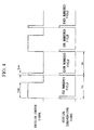
- FIG. 4 is an explanatory diagram showing the emission control signal which is output from the emission control section 14 in synchronization with the vertical synchronizing signal which is output to the short baseline length camera 12 and the long baseline length camera 13.
- the short baseline length camera 12 and the long baseline length camera 13 are interlaced scanning cameras wherein a single frame is formed from two fields, an odd numbered field and an even numbered field.
- the image for each field is obtained by scanning in synchronization with the vertical synchronizing signal.
- the scanning time "to" of the odd numbered field and the scanning time "te" of the even numbered field are the same.
- the emission control signal is a pulse signal having a variable pulse width, which is output in synchronization with the vertical synchronizing signal.
- the laser emitting section 21 receives input of this emission control signal and emits laser light based on this emission control signal.
- the ON or OFF state of the laser light emitted from the laser emitting section 21 is controlled so that the laser light is emitted only when the emission control signal is at a high level.
- the PWM comprised within the emission control section 14 then outputs a pulse with a pulse width of "tow” in synchronization with the vertical synchronizing signal of the odd numbered field, and moreover outputs a pulse with a pulse width of "tew” in synchronization with the vertical synchronizing signal of the even numbered field.
- the intensity of the light received by the CCD of the imaging camera is closely proportional to the time period during the field scanning time for which light was emitted. In other words, even when strong light is projected onto a close object, if the length of time for which the light is projected is short, the effect will be the same as if weak light had been projected onto the object throughout the field scanning time. Consequently, the pulse width "tow" should be set at a pulse width whereby imaging is possible for reflected light from laser light projected onto a distant object.
- the pulse width "tew” should be set at a pulse width whereby satisfactory imaging is possible for reflected light from laser light projected onto a close object.
- the largest possible width for the pulse width "tow” is the scanning time "to" of the odd numbered field, and furthermore the pulse width "tew” must be a shorter time than the pulse width "tow”.
- the emission control section 14 also outputs the vertical synchronizing signal to the short baseline length camera 12 and the long baseline length camera 13.
- the laser emitting section 21 receives this signal and emits laser light, and the short baseline length camera 12 and the long baseline length camera 13 scan and output an image to the image memory in the image storing section 15 used for storing the odd numbered fields.
- the image storing section 15 then removes those pixels of very high brightness from the images, based on a predetermined threshold. Because the images obtained are odd numbered field images at a timing wherein strong laser light is projected, the pixels of high brightness represent close objects. Consequently, if pixels with high brightness are removed based on a predetermined threshold, it becomes possible to target the measurement of only distant objects.
- the short baseline length camera 12 and the long baseline length camera 13 scan the image again, and output to the image memory in the image storing section 15 used for storing even numbered fields.
- the image storing section 15 then removes those pixels of low brightness based on a predetermined threshold. Because the images thus obtained are even numbered field images at a timing wherein weak laser light is projected, the pixels with low brightness represent far-off objects. Consequently, if pixels with low brightness are removed based on a predetermined threshold, it becomes possible to target the measurement of only close objects.
- the image storing section 15 outputs the stored image to the height estimating section 16. Based on this image, the height estimating section 16 determines the distance to each pixel which shows the reflected light of the slit light using the principle of triangulation, and then executes the height estimation process. The height estimating section 16 then corrects the height estimated from the odd numbered field and the even numbered field respectively to compensate for momentum of the robot 1, and produces a height estimation result.
- the light emission intensity of the laser light is changed within the field scanning time, two field images each having a different light emission intensity are captured, and the pixels of a high brightness or a low brightness are removed based on a predetermined threshold, and consequently it becomes possible to take an image of the slit light at a uniform intensity of received light, regardless of the distance to the object. Consequently, it is possible to narrow down the dynamic range for imaging the slit light, and as a result it becomes possible to detect minute variations in brightness.
- the emission time of the laser light could also be controlled so that the slit light projected onto the floor surface is imaged by the short baseline length camera 12 and the long baseline length camera 13, and the pulse widths "tow", "tew” are then determined, based on the state of the image obtained, so that the brightness distribution of the slit light is uniform.
- the emission time may be changed according to the reflective properties of an obstacle or the distance to an obstacle.
- the brightness distribution of the reflected light is made uniform in this manner, it is possible to avoid situations where the brightness falls outside the dynamic range of the camera, and so object recognition and distance measurement can be carried out accurately.
- a distance measuring apparatus which utilizes a light-section method capable of measuring both close objects and far away objects without adjusting the dynamic range of an imaging camera.
- the apparatus comprises: an image acquisition section (11, 12, 13, 15) for imaging reflected light which has been emitted from the apparatus, has passed through a slit, and has then been reflected off the surface of a target object; an emission control section (14) for controlling the emission time (tow, tew) of the slit light during the time (to, te) an image is being scanned by the image acquisition section, and for changing the intensity of the received light in the image acquisition section; and a distance calculation section (16) for calculating the distance to the object based on the image taken by the image acquisition section and a positional relationship between a light emission position of the slit light and an image position.
Landscapes
- Engineering & Computer Science (AREA)
- Physics & Mathematics (AREA)
- Computer Networks & Wireless Communication (AREA)
- General Physics & Mathematics (AREA)
- Radar, Positioning & Navigation (AREA)
- Remote Sensing (AREA)
- Electromagnetism (AREA)
- Measurement Of Optical Distance (AREA)
- Length Measuring Devices By Optical Means (AREA)
- Optical Radar Systems And Details Thereof (AREA)
Abstract
Description
Claims (8)
- A distance measuring apparatus comprising:an image acquisition section (11, 12, 13, 15) for imaging reflected light which has been emitted from the apparatus, has passed through a slit, and has then been reflected off the surface of a target object to be measured;an emission control section (14) for controlling the emission time (tow, tew) of the light which is emitted and passes through the slit during the time (to, te) an image is being scanned by the image acquisition section, and for changing the intensity of the received light in the image acquisition section; anda distance calculation section (16) for calculating the distance to the object based on the image taken by the image acquisition section by referring to a positional relationship between a light emission position of the light passing through the slit and an image position.
- A distance measuring apparatus according to claim 1, wherein the emission control section is constructed so as to determine the emission time according to the intensity of the reflected light received by the image acquisition section.
- A distance measuring apparatus according to claim 1, wherein the image acquisition section removes pixels of a higher brightness than a predetermined first threshold value from obtained images to generate images for a timing in which a relatively strong light is being projected, and removes pixels of a lower brightness than a predetermined second threshold value from obtained images to generates images for a timing in which a relatively weak light is being projected.
- A self-controlled robot incorporating a distance measuring apparatus according to claim 1.
- A self-controlled robot according to claim 4, wherein the self-controlled robot is a bipedal robot(1).
- A distance measuring method comprising the steps of:emitting light which has passed through a slit onto a target object to be measured;imaging light reflected by the object by an imaging section (12, 13, 15);based on the obtained image, measuring the distance to the object by referring to a positional relationship between a light emission position of the light which has passed through the slit and an image position; andwhen the light passed through the slit is projected onto the object, varying an emission time (tow, tew) of the light passed through the slit within a time period (to, te) during which the imaging section scans the image.
- A distance measuring method according to claim 6, wherein the intensity of the emitted light which passes through the slit and is projected onto the object is changed in accordance with the intensity of the imaged light reflected off the surface of the object.
- A distance measuring method according to claim 6, wherein
pixels of a higher brightness than a predetermined first threshold value are removed from obtained images to generate images for a timing in which a relatively strong light is being projected;
pixels of a lower brightness than a predetermined second threshold value are removed from obtained images to generates images for a timing in which a relatively weak light is being projected; and
the distance is measured based on the generated images.
Applications Claiming Priority (2)
| Application Number | Priority Date | Filing Date | Title |
|---|---|---|---|
| JP2000328284 | 2000-10-27 | ||
| JP2000328284A JP2002131016A (en) | 2000-10-27 | 2000-10-27 | Distance measuring device and distance measuring method |
Publications (3)
| Publication Number | Publication Date |
|---|---|
| EP1202075A2 true EP1202075A2 (en) | 2002-05-02 |
| EP1202075A3 EP1202075A3 (en) | 2003-04-23 |
| EP1202075B1 EP1202075B1 (en) | 2007-01-03 |
Family
ID=18805157
Family Applications (1)
| Application Number | Title | Priority Date | Filing Date |
|---|---|---|---|
| EP01125667A Expired - Lifetime EP1202075B1 (en) | 2000-10-27 | 2001-10-26 | Distance measuring apparatus and distance measuring method |
Country Status (4)
| Country | Link |
|---|---|
| US (1) | US6721679B2 (en) |
| EP (1) | EP1202075B1 (en) |
| JP (1) | JP2002131016A (en) |
| DE (1) | DE60125683T2 (en) |
Cited By (5)
| Publication number | Priority date | Publication date | Assignee | Title |
|---|---|---|---|---|
| EP1835306A1 (en) * | 2006-03-17 | 2007-09-19 | Valeo Vision | Method and device for detecting an obstacle near a moving vehicle |
| CN100430752C (en) * | 2002-10-18 | 2008-11-05 | 株式会社拓普康 | position measuring device |
| WO2014111357A1 (en) * | 2013-01-18 | 2014-07-24 | Archos | Method and system for providing a mobile device with information on the position thereof relative to a target, robot integrating such a system and tablet |
| CN112965080A (en) * | 2021-02-04 | 2021-06-15 | 郜键 | Flash type slit-free stripe camera laser area array imaging method, system and device |
| CN116336965A (en) * | 2023-05-31 | 2023-06-27 | 天津宜科自动化股份有限公司 | Data processing system for acquiring object contour information |
Families Citing this family (24)
| Publication number | Priority date | Publication date | Assignee | Title |
|---|---|---|---|---|
| US7117047B1 (en) * | 2001-12-04 | 2006-10-03 | Assembly Guidance Systems, Inc. | High accuracy inspection system and method for using same |
| JP4262196B2 (en) * | 2004-12-14 | 2009-05-13 | 本田技研工業株式会社 | Autonomous mobile robot |
| DE102004062022A1 (en) * | 2004-12-23 | 2006-07-13 | Robert Bosch Gmbh | Optical proximity sensor |
| JP4200328B2 (en) * | 2005-04-18 | 2008-12-24 | パナソニック電工株式会社 | Spatial information detection system |
| JP5082332B2 (en) * | 2006-08-17 | 2012-11-28 | 日産自動車株式会社 | Distance measuring system |
| JP2008298741A (en) * | 2007-06-04 | 2008-12-11 | Toyota Central R&D Labs Inc | Distance measuring device and distance measuring method |
| KR100884904B1 (en) * | 2007-09-12 | 2009-02-19 | 아주대학교산학협력단 | Magnetic Position Recognition Using Parallel Projection Model |
| KR101165122B1 (en) * | 2007-10-10 | 2012-07-12 | 주식회사 만도 | Light Stripe Detection Method for Indoor Navigation and Parking Assist Apparatus Using Same |
| JP5104355B2 (en) * | 2008-02-01 | 2012-12-19 | 富士通株式会社 | Robot control apparatus, robot control method, and robot control program |
| US20100292884A1 (en) * | 2009-05-12 | 2010-11-18 | Rogelio Manfred Neumann | Device for Influencing Navigation of an Autonomous Vehicle |
| JP5284923B2 (en) * | 2009-10-28 | 2013-09-11 | 本田技研工業株式会社 | Control device for legged mobile robot |
| DE102010018979A1 (en) * | 2010-05-03 | 2011-11-03 | Steinbichler Optotechnik Gmbh | Method and device for determining the 3D coordinates of an object |
| US9383753B1 (en) | 2012-09-26 | 2016-07-05 | Google Inc. | Wide-view LIDAR with areas of special attention |
| KR20150057547A (en) * | 2013-11-20 | 2015-05-28 | 삼성디스플레이 주식회사 | Organic light emitting display device |
| CN105157646B (en) * | 2015-09-07 | 2018-08-24 | 戴纳派克(中国)压实摊铺设备有限公司 | Paving width measuring system, paver and paving width measurement method |
| CN108431631A (en) | 2015-12-21 | 2018-08-21 | 株式会社小糸制作所 | Vehicle image acquiring device, control device, include vehicle image acquiring device or control device vehicle and vehicle image acquiring method |
| JP6766071B2 (en) | 2015-12-21 | 2020-10-07 | 株式会社小糸製作所 | Image acquisition device for vehicles and vehicles equipped with it |
| EP3396413A4 (en) | 2015-12-21 | 2019-08-21 | Koito Manufacturing Co., Ltd. | Image acquisition device for vehicles, control device, vehicle provided with image acquisition device for vehicles and control device, and image acquisition method for vehicles |
| JP6851986B2 (en) | 2015-12-21 | 2021-03-31 | 株式会社小糸製作所 | Vehicle and vehicle image acquisition method equipped with vehicle image acquisition device, control device, vehicle image acquisition device or control device |
| KR102598711B1 (en) | 2016-07-07 | 2023-11-06 | 삼성전자주식회사 | lidar apparatus emitting non-uniform light and autonomous robot comprising thereof |
| CN110007289B (en) * | 2019-03-21 | 2021-09-21 | 杭州蓝芯科技有限公司 | Motion artifact reduction method based on time-of-flight depth camera |
| CN120143184A (en) * | 2019-09-30 | 2025-06-13 | 富士胶片株式会社 | Processing device, electronic device, processing method and computer program product |
| CN116482708A (en) * | 2023-03-23 | 2023-07-25 | 奥比中光科技集团股份有限公司 | TOF and structured light combined depth camera, depth detection method thereof and sweeper |
| CN116501070B (en) * | 2023-06-30 | 2023-09-19 | 深圳市欢创科技有限公司 | Recharging method, robot and storage medium |
Family Cites Families (17)
| Publication number | Priority date | Publication date | Assignee | Title |
|---|---|---|---|---|
| CA1266562A (en) | 1986-09-24 | 1990-03-13 | Donald Stewart | Distance measuring apparatus |
| US4954962A (en) * | 1988-09-06 | 1990-09-04 | Transitions Research Corporation | Visual navigation and obstacle avoidance structured light system |
| CA2038818A1 (en) * | 1990-03-30 | 1991-10-01 | Akio Nagamune | Distance measuring method and apparatus therefor |
| US5225882A (en) | 1991-04-23 | 1993-07-06 | Nec Corporation | Moving body measuring apparatus |
| JPH05119154A (en) | 1991-10-30 | 1993-05-18 | Fujitsu Ten Ltd | On-vehicle laser radar apparatus |
| JP3282332B2 (en) | 1993-12-20 | 2002-05-13 | ミノルタ株式会社 | Image input system |
| US6028672A (en) * | 1996-09-30 | 2000-02-22 | Zheng J. Geng | High speed three dimensional imaging method |
| US5812269A (en) | 1996-07-29 | 1998-09-22 | General Scanning, Inc. | Triangulation-based 3-D imaging and processing method and system |
| JP3417222B2 (en) * | 1996-08-07 | 2003-06-16 | 松下電器産業株式会社 | Real-time range finder |
| JP3672731B2 (en) | 1997-09-04 | 2005-07-20 | 松下電器産業株式会社 | Range finder device |
| US6204916B1 (en) * | 1998-02-03 | 2001-03-20 | Minolta Co., Ltd. | Three dimensional information measurement method and apparatus |
| JP4111592B2 (en) * | 1998-06-18 | 2008-07-02 | コニカミノルタセンシング株式会社 | 3D input device |
| JP2000153476A (en) * | 1998-09-14 | 2000-06-06 | Honda Motor Co Ltd | Legged mobile robot |
| JP3695188B2 (en) | 1998-12-21 | 2005-09-14 | 富士ゼロックス株式会社 | Shape measuring apparatus and shape measuring method |
| EP1037069A3 (en) * | 1999-03-17 | 2004-01-14 | Matsushita Electric Industrial Co., Ltd. | Rangefinder |
| JP2000283721A (en) * | 1999-03-30 | 2000-10-13 | Minolta Co Ltd | Three-dimensional input device |
| JP3711808B2 (en) | 1999-10-07 | 2005-11-02 | 富士ゼロックス株式会社 | Shape measuring apparatus and shape measuring method |
-
2000
- 2000-10-27 JP JP2000328284A patent/JP2002131016A/en not_active Withdrawn
-
2001
- 2001-10-26 EP EP01125667A patent/EP1202075B1/en not_active Expired - Lifetime
- 2001-10-26 DE DE60125683T patent/DE60125683T2/en not_active Expired - Lifetime
- 2001-10-26 US US09/984,040 patent/US6721679B2/en not_active Expired - Fee Related
Cited By (10)
| Publication number | Priority date | Publication date | Assignee | Title |
|---|---|---|---|---|
| CN100430752C (en) * | 2002-10-18 | 2008-11-05 | 株式会社拓普康 | position measuring device |
| EP1411371B1 (en) * | 2002-10-18 | 2010-12-01 | Kabushiki Kaisha TOPCON | Surveying and position measuring instrument with a fan-shapped light beam |
| EP1835306A1 (en) * | 2006-03-17 | 2007-09-19 | Valeo Vision | Method and device for detecting an obstacle near a moving vehicle |
| FR2898687A1 (en) * | 2006-03-17 | 2007-09-21 | Valeo Vision Sa | METHOD AND DEVICE FOR DETECTING AN OBSTACLE IN THE NEIGHBORHOOD OF A MOVING VEHICLE |
| WO2014111357A1 (en) * | 2013-01-18 | 2014-07-24 | Archos | Method and system for providing a mobile device with information on the position thereof relative to a target, robot integrating such a system and tablet |
| FR3001298A1 (en) * | 2013-01-18 | 2014-07-25 | Archos | METHOD AND SYSTEM FOR PROVIDING A MOBILE DEVICE WITH INFORMATION ON ITS POSITION IN RELATION TO A TARGET, ROBOT INCORPORATING SUCH A SYSTEM AND TABLET |
| CN112965080A (en) * | 2021-02-04 | 2021-06-15 | 郜键 | Flash type slit-free stripe camera laser area array imaging method, system and device |
| CN112965080B (en) * | 2021-02-04 | 2024-02-20 | 苏州奥瑞图光电科技有限公司 | Flash slit-free stripe camera laser array imaging method, system and device |
| CN116336965A (en) * | 2023-05-31 | 2023-06-27 | 天津宜科自动化股份有限公司 | Data processing system for acquiring object contour information |
| CN116336965B (en) * | 2023-05-31 | 2023-09-05 | 天津宜科自动化股份有限公司 | Data processing system for acquiring object contour information |
Also Published As
| Publication number | Publication date |
|---|---|
| EP1202075B1 (en) | 2007-01-03 |
| DE60125683D1 (en) | 2007-02-15 |
| DE60125683T2 (en) | 2007-04-26 |
| JP2002131016A (en) | 2002-05-09 |
| US20020052711A1 (en) | 2002-05-02 |
| US6721679B2 (en) | 2004-04-13 |
| EP1202075A3 (en) | 2003-04-23 |
Similar Documents
| Publication | Publication Date | Title |
|---|---|---|
| US6721679B2 (en) | Distance measuring apparatus and distance measuring method | |
| US6483536B2 (en) | Distance measuring apparatus and method employing two image taking devices having different measurement accuracy | |
| US6683675B2 (en) | Distance measuring apparatus and distance measuring method | |
| US6549288B1 (en) | Structured-light, triangulation-based three-dimensional digitizer | |
| US9170097B2 (en) | Hybrid system | |
| US5889582A (en) | Image-directed active range finding system | |
| US6765606B1 (en) | Three dimension imaging by dual wavelength triangulation | |
| CN112740065B (en) | Imaging device, imaging method and depth mapping method | |
| US20240061090A1 (en) | Time-of-flight demodulation circuitry, time-of-flight demodulation method, time-of-flight imaging apparatus, time-of-flight imaging apparatus control method | |
| WO2022050279A1 (en) | Three-dimensional measurement device | |
| JP2020160044A (en) | Distance measuring device and distance measuring method | |
| US6927864B2 (en) | Method and system for determining dimensions of optically recognizable features | |
| JP7628462B2 (en) | Laser measurement device and method | |
| US12493121B2 (en) | High resolution lidar scanning | |
| US20220196386A1 (en) | Three-dimensional scanner with event camera | |
| TW200902964A (en) | System and method for height measurement | |
| JPS62194413A (en) | Three-dimensional coordinate measuring instrument | |
| JP2566395B2 (en) | Three-dimensional coordinate measuring device | |
| EP1202074A2 (en) | Distance measuring apparatus and distance measuring method | |
| US20210014401A1 (en) | Three-dimensional distance measuring method and device | |
| JP2023068814A (en) | distance measurement device, distance measurement program | |
| JP2775924B2 (en) | Image data creation device | |
| RU2811331C1 (en) | Device for forming image of map of distances to surveyed objects | |
| JPH11183142A (en) | Method and apparatus for picking up three-dimensional image | |
| JP2009186216A (en) | 3D shape measuring device |
Legal Events
| Date | Code | Title | Description |
|---|---|---|---|
| PUAI | Public reference made under article 153(3) epc to a published international application that has entered the european phase |
Free format text: ORIGINAL CODE: 0009012 |
|
| AK | Designated contracting states |
Kind code of ref document: A2 Designated state(s): AT BE CH CY DE DK ES FI FR GB GR IE IT LI LU MC NL PT SE TR |
|
| AX | Request for extension of the european patent |
Free format text: AL;LT;LV;MK;RO;SI |
|
| PUAL | Search report despatched |
Free format text: ORIGINAL CODE: 0009013 |
|
| AK | Designated contracting states |
Designated state(s): AT BE CH CY DE DK ES FI FR GB GR IE IT LI LU MC NL PT SE TR |
|
| AX | Request for extension of the european patent |
Extension state: AL LT LV MK RO SI |
|
| RIC1 | Information provided on ipc code assigned before grant |
Ipc: 7G 01S 7/497 B Ipc: 7G 01B 11/02 B Ipc: 7G 01B 11/24 B Ipc: 7G 01S 17/42 A Ipc: 7G 01S 7/491 B |
|
| 17P | Request for examination filed |
Effective date: 20031022 |
|
| AKX | Designation fees paid |
Designated state(s): DE GB |
|
| 17Q | First examination report despatched |
Effective date: 20040126 |
|
| GRAP | Despatch of communication of intention to grant a patent |
Free format text: ORIGINAL CODE: EPIDOSNIGR1 |
|
| GRAS | Grant fee paid |
Free format text: ORIGINAL CODE: EPIDOSNIGR3 |
|
| GRAA | (expected) grant |
Free format text: ORIGINAL CODE: 0009210 |
|
| AK | Designated contracting states |
Kind code of ref document: B1 Designated state(s): DE GB |
|
| REG | Reference to a national code |
Ref country code: GB Ref legal event code: FG4D |
|
| REF | Corresponds to: |
Ref document number: 60125683 Country of ref document: DE Date of ref document: 20070215 Kind code of ref document: P |
|
| PLBE | No opposition filed within time limit |
Free format text: ORIGINAL CODE: 0009261 |
|
| STAA | Information on the status of an ep patent application or granted ep patent |
Free format text: STATUS: NO OPPOSITION FILED WITHIN TIME LIMIT |
|
| 26N | No opposition filed |
Effective date: 20071005 |
|
| PGFP | Annual fee paid to national office [announced via postgrant information from national office to epo] |
Ref country code: DE Payment date: 20101020 Year of fee payment: 10 |
|
| PGFP | Annual fee paid to national office [announced via postgrant information from national office to epo] |
Ref country code: GB Payment date: 20101020 Year of fee payment: 10 |
|
| GBPC | Gb: european patent ceased through non-payment of renewal fee |
Effective date: 20111026 |
|
| PG25 | Lapsed in a contracting state [announced via postgrant information from national office to epo] |
Ref country code: GB Free format text: LAPSE BECAUSE OF NON-PAYMENT OF DUE FEES Effective date: 20111026 |
|
| PG25 | Lapsed in a contracting state [announced via postgrant information from national office to epo] |
Ref country code: DE Free format text: LAPSE BECAUSE OF NON-PAYMENT OF DUE FEES Effective date: 20130501 |
|
| REG | Reference to a national code |
Ref country code: DE Ref legal event code: R119 Ref document number: 60125683 Country of ref document: DE Effective date: 20130501 |